EP0543709A1 - Schutzkappe für Knochennagel mit Werkzeug zu deren Befestigung - Google Patents
Schutzkappe für Knochennagel mit Werkzeug zu deren Befestigung Download PDFInfo
- Publication number
- EP0543709A1 EP0543709A1 EP92403068A EP92403068A EP0543709A1 EP 0543709 A1 EP0543709 A1 EP 0543709A1 EP 92403068 A EP92403068 A EP 92403068A EP 92403068 A EP92403068 A EP 92403068A EP 0543709 A1 EP0543709 A1 EP 0543709A1
- Authority
- EP
- European Patent Office
- Prior art keywords
- cap
- screw
- pin
- spindle
- fracture
- Prior art date
- Legal status (The legal status is an assumption and is not a legal conclusion. Google has not performed a legal analysis and makes no representation as to the accuracy of the status listed.)
- Granted
Links
- 230000001681 protective effect Effects 0.000 title claims description 17
- 210000000988 bone and bone Anatomy 0.000 claims description 11
- 230000000903 blocking effect Effects 0.000 claims description 3
- 238000013508 migration Methods 0.000 abstract description 4
- 230000005012 migration Effects 0.000 abstract description 4
- 230000007704 transition Effects 0.000 abstract 1
- 206010017076 Fracture Diseases 0.000 description 25
- 208000010392 Bone Fractures Diseases 0.000 description 24
- 239000007943 implant Substances 0.000 description 10
- 230000006835 compression Effects 0.000 description 7
- 238000007906 compression Methods 0.000 description 7
- 208000037873 arthrodesis Diseases 0.000 description 5
- 208000000013 Hammer Toe Syndrome Diseases 0.000 description 4
- 240000007817 Olea europaea Species 0.000 description 3
- 229910000831 Steel Inorganic materials 0.000 description 3
- 238000002679 ablation Methods 0.000 description 3
- 210000001503 joint Anatomy 0.000 description 3
- 239000010959 steel Substances 0.000 description 3
- 210000003813 thumb Anatomy 0.000 description 3
- 208000027502 Ankle fracture Diseases 0.000 description 2
- 206010061159 Foot deformity Diseases 0.000 description 2
- 208000002607 Pseudarthrosis Diseases 0.000 description 2
- 210000003423 ankle Anatomy 0.000 description 2
- 238000007596 consolidation process Methods 0.000 description 2
- 238000012937 correction Methods 0.000 description 2
- 238000000605 extraction Methods 0.000 description 2
- 210000001255 hallux Anatomy 0.000 description 2
- 230000007794 irritation Effects 0.000 description 2
- 230000003902 lesion Effects 0.000 description 2
- 210000000811 metacarpophalangeal joint Anatomy 0.000 description 2
- 210000002221 olecranon process Anatomy 0.000 description 2
- 238000002559 palpation Methods 0.000 description 2
- 230000007170 pathology Effects 0.000 description 2
- 230000005855 radiation Effects 0.000 description 2
- 238000011477 surgical intervention Methods 0.000 description 2
- 238000001356 surgical procedure Methods 0.000 description 2
- 210000000457 tarsus Anatomy 0.000 description 2
- 210000001519 tissue Anatomy 0.000 description 2
- 210000000623 ulna Anatomy 0.000 description 2
- 208000003322 Coinfection Diseases 0.000 description 1
- 206010034122 Patella fracture Diseases 0.000 description 1
- 206010043248 Tendon rupture Diseases 0.000 description 1
- 206010048049 Wrist fracture Diseases 0.000 description 1
- 238000013459 approach Methods 0.000 description 1
- 238000011882 arthroplasty Methods 0.000 description 1
- 210000003010 carpal bone Anatomy 0.000 description 1
- 208000015181 infectious disease Diseases 0.000 description 1
- 239000000463 material Substances 0.000 description 1
- 210000000236 metacarpal bone Anatomy 0.000 description 1
- 210000001872 metatarsal bone Anatomy 0.000 description 1
- 210000000878 metatarsophalangeal joint Anatomy 0.000 description 1
- 210000003789 metatarsus Anatomy 0.000 description 1
- 238000000034 method Methods 0.000 description 1
- 210000002346 musculoskeletal system Anatomy 0.000 description 1
- 210000004417 patella Anatomy 0.000 description 1
- 238000000926 separation method Methods 0.000 description 1
- 210000001137 tarsal bone Anatomy 0.000 description 1
- 239000004753 textile Substances 0.000 description 1
- 210000003371 toe Anatomy 0.000 description 1
- 230000001052 transient effect Effects 0.000 description 1
- 238000013519 translation Methods 0.000 description 1
- 208000017013 ulna fracture Diseases 0.000 description 1
- 239000013598 vector Substances 0.000 description 1
- 238000003466 welding Methods 0.000 description 1
Images

Classifications
-
- A—HUMAN NECESSITIES
- A61—MEDICAL OR VETERINARY SCIENCE; HYGIENE
- A61B—DIAGNOSIS; SURGERY; IDENTIFICATION
- A61B17/00—Surgical instruments, devices or methods
- A61B17/56—Surgical instruments or methods for treatment of bones or joints; Devices specially adapted therefor
- A61B17/58—Surgical instruments or methods for treatment of bones or joints; Devices specially adapted therefor for osteosynthesis, e.g. bone plates, screws or setting implements
- A61B17/68—Internal fixation devices, including fasteners and spinal fixators, even if a part thereof projects from the skin
- A61B17/685—Elements to be fitted on the end of screws or wires, e.g. protective caps
-
- A—HUMAN NECESSITIES
- A61—MEDICAL OR VETERINARY SCIENCE; HYGIENE
- A61B—DIAGNOSIS; SURGERY; IDENTIFICATION
- A61B90/00—Instruments, implements or accessories specially adapted for surgery or diagnosis and not covered by any of the groups A61B1/00 - A61B50/00, e.g. for luxation treatment or for protecting wound edges
- A61B90/03—Automatic limiting or abutting means, e.g. for safety
- A61B2090/037—Automatic limiting or abutting means, e.g. for safety with a frangible part, e.g. by reduced diameter
Definitions
- the present invention relates to a protective cap for an osteosynthesis pin as well as an assembly comprising this cap and a member for fixing the cap on the pin.
- the object of the invention is to propose a satisfactory solution to the problem set out above.
- the protective cap of the spindle comprises a housing adapted to receive one end of the spindle, and a tapped hole opening transversely into this housing, adapted to receive a fixing screw making it possible to secure the spindle and the cap.
- the screw has a fragile zone allowing its rupture at the end of screwing and the blocking of the screw in the hole transverse
- Such a cap forms at the end of the spindle a prominence which effectively opposes any unwanted movement of this spindle.
- the invention also relates to an assembly allowing the establishment of the cap and the locking of its screw on the spindle to fix the cap to the latter.
- this assembly comprises a cap and a member for fixing the cap on the spindle, provided with an end part made one piece with the screw, a weakened zone of rupture at the end of screwing being provided between the screw and said terminal part.
- the cap locking screw on the spindle is initially part of its fitting tool, from which it does not become detached until the end of screwing, by breaking the weakened area.
- This arrangement avoids the use of a screwdriver, which would be particularly difficult under the conditions of the surgical intervention and taking into account the small dimensions of the screw and of the cap.
- the device shown in Fig. 1 comprises a cap 1 for protecting a spinal osteosynthesis pin such as 2 (Fig. 2), a member 3 for fixing the cap 1 on the spindle, this member being provided with a part terminal 4 for supporting the cap 1, and finally a protective cover 5 covering the terminal part 4 and the cap 1.
- the cover 5, made for example of any suitable plastic material, has a tubular shape and can be frictionally fitted onto a cylindrical base 6 coaxial with the end portion 4. This base 6 is extended by a handle 7 for manual handling, the surface of which is preferably coated with roughness, for example a knurling 8.
- the cap 1 shown in detail in Fig. 2 and 3, comprises a housing 9 formed by a blind hole adapted to receive one end of the pin 2.
- a tapped hole 11 is further formed opening out transversely into the housing 9, and adapted to receive a screw 12 for securing the spindle 2 and the cap 1.
- the hole 11 passes right through the cap 1, perpendicular to the axis of the cylindrical housing 9, only its part intended to receive the screw 12 being tapped.
- the screw 12 has a head 12a adapted to match the cylindrical surface of the spindle 2. It is produced one piece with the end part 4 of the screw handle 3, and has, at its junction with the end of this part 4, a zone fragile 13 allowing its rupture at the end of screwing and thus the separation of the screw 12 relative to the neck forming the terminal part 4.
- the surgeon After removing the cap 5, the surgeon, holding the handle 7 in his hand, approaches the cap 1 to the end of the spindle 2 which he introduces into the housing 9, until its tip comes into abutment on the bottom of this housing. Then, the screw 12 being only partially inserted into its hole 11, the surgeon begins to screw it in by turning the tool 3 like a screwdriver. At the end of screwing, the head 12a of the screw 12 is applied tightly against the spindle 2 which it blocks in translation and in rotation relative to the cap 1. Then, by forcing on the handle 7, the surgeon causes the rupture of the fragile zone 13, located at this moment inside the tapped hole 11. The screw 12 is then in place and fixes the cap 1 to the pin 2.
- the second embodiment of the cap 14, shown in Figs. 4 and 5, differs from the previous one in that the body of the cap is larger and perforated by a bore 15, preferably oriented perpendicular to the axis of the housing 9 and therefore to the spindle 2.
- the bore 15 passes right through the cap 14, and allows the passage of a strapping wire or bone guying, as will be explained in more detail below.
- the cavity 9 receiving the pin 2 can have a variable diameter, adapted to that of the pin, which can also be unthreaded, or else partially or fully threaded.
- Fig.6 illustrates the application of the invention to the fracture 16 of a ball joint 10: the device comprises two pins 17 each of whose two ends is capped with an implant cap 14 in the holes 15 through which passes a wire 18 , for example steel.
- This wire the two ends of which are knotted at 18a, forms a hooping or guying to maintain the compression of the two parts of the fractured patella.
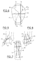
- Fig.7 is a posterior view of the upper end of a fractured ulna 40 (olecranon), equipped with two pins 19 each provided with a cap 14, crossed by a steel wire 18 whose ends have been knotted so as to form a closed loop which crosses a bone channel 20.
- Fig.8 shows the lower end of a radius 22, with two fracture lines 21, equipped with a device according to the invention with three pins 23, the projecting ends of the radius 22 are each capped by a cap 1.
- the arrangement shown in Fig.8 constitutes an intrafocal plug-in according to Kapandji
- Fig. 9 shows a radius 22, the lower end of which has a single fracture line 21, and which is provided with two crossed pins 23, the ends of which protrude outside the radius are each capped with a cap 1. This is a styloid plug-in.
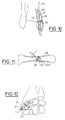
- Fig.10 illustrates an assembly according to the invention of two pins 23 on an ankle 24 having suffered an internal malleolar fracture 25.
- Each pin 23 has its end projecting outwardly from the ankle 24 capped by a cap 14 crossed by a wire 26 , for example of steel, forming a closed loop which crosses a tibial transossous canal 27.
- a wire 26 for example of steel
- Fig.11 shows a metacarpal 28 whose fracture 29 is crossed by a pin 23.
- the distal end 23a of the pin 23 is threaded and crosses the cortex, while the proximal end is coated with a protective cap 1.
- the assembly of the pin 23 and the cap 1 is screwed, by means of pliers as indicated by the arrow K, to develop a compression at the level of the fracture site. This compression is induced by the slight translational movement of the spindle caused by its rotation. This is applicable to the other bones of the musculoskeletal system.
- Fig.12 shows a fractured carpal scaphoid 31, provided with two pins 23 whose ends outside the scaphoid are capped with a cap 1.
- a device is applicable to the surgical treatment of pseudarthoses of the carpal scaphoid, whether or not combining it with a bone graft, other carpal or tarsal bones, tarsus in fractures-dislocations involving the tarsus and metatarsus, or any other pathology tarsal and metatarsal fracture
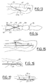
- Fig. 13 is an example of application of the invention to an arthrodesis (welding of the two parts of the joint to one another) of digital joint, such as the distal (or proximal) interphalangeal.
- the two parts 41, 42 of the fractured bone are kept in alignment by an axial pin 23 (smooth or threaded) supplemented by a small anti-rotation pin 23a, oblique to the pin 23 so as to prevent one of the two parts of the bone to rotate relative to each other.
- Each of the two pins has a cap 1.
- Fig. 14 illustrates an arthrodesis of the metacarpophalangeal joint 32 of the thumb 33, or of the metatarsophalangeal joint of the big toe.
- the device here comprises two pins 23 each provided with a cap 14 traversed by a wire 33 using a transossous passage 34.
- Such a device is also applicable to the interphalangeal joint of the thumb and the big toe.
- Fig. 15 shows protection of a suture of the distal extensor (30) with transient blockage of the distal interphalangeal joint by a pin 23 provided with a cap 1 (this pin is to be maintained for 4 to 6 weeks) .
- Fig. 16 shows a claw toe 35, into the digital canal of which was inserted, close to the bone, a support pin 23 provided with a cap 1, after a modeling arthroplasty of the proximal interphalangeal joint of the 'toe.
- Fig. 17 shows a hammer toe 35a on which a distal interphalangeal tenodermodesis was performed, then in the digital channel from which a stent pin 23 was temporarily put in place.
Landscapes
- Health & Medical Sciences (AREA)
- Orthopedic Medicine & Surgery (AREA)
- Surgery (AREA)
- Life Sciences & Earth Sciences (AREA)
- Heart & Thoracic Surgery (AREA)
- Animal Behavior & Ethology (AREA)
- Engineering & Computer Science (AREA)
- Biomedical Technology (AREA)
- Neurology (AREA)
- Medical Informatics (AREA)
- Molecular Biology (AREA)
- Nuclear Medicine, Radiotherapy & Molecular Imaging (AREA)
- General Health & Medical Sciences (AREA)
- Public Health (AREA)
- Veterinary Medicine (AREA)
- Surgical Instruments (AREA)
- Prostheses (AREA)
- Orthopedics, Nursing, And Contraception (AREA)
Applications Claiming Priority (2)
| Application Number | Priority Date | Filing Date | Title |
|---|---|---|---|
| FR9114184 | 1991-11-18 | ||
| FR9114184A FR2683712B1 (fr) | 1991-11-18 | 1991-11-18 | Capuchon de protection d'une broche d'osteosynthese et ensemble comportant ce capuchon ainsi qu'un organe pour sa fixation sur la broche. |
Publications (2)
| Publication Number | Publication Date |
|---|---|
| EP0543709A1 true EP0543709A1 (de) | 1993-05-26 |
| EP0543709B1 EP0543709B1 (de) | 1997-07-30 |
Family
ID=9419052
Family Applications (1)
| Application Number | Title | Priority Date | Filing Date |
|---|---|---|---|
| EP92403068A Expired - Lifetime EP0543709B1 (de) | 1991-11-18 | 1992-11-13 | Schutzkappe für Knochennagel mit Werkzeug zu deren Befestigung |
Country Status (8)
| Country | Link |
|---|---|
| US (1) | US5330476A (de) |
| EP (1) | EP0543709B1 (de) |
| JP (1) | JPH06181932A (de) |
| AT (1) | ATE155990T1 (de) |
| CA (1) | CA2083127C (de) |
| DE (1) | DE69221266T2 (de) |
| ES (1) | ES2108741T3 (de) |
| FR (1) | FR2683712B1 (de) |
Cited By (3)
| Publication number | Priority date | Publication date | Assignee | Title |
|---|---|---|---|---|
| FR2765094A1 (fr) * | 1997-06-26 | 1998-12-31 | Somepic Technologie | Dispositif de mise en place d'un capuchon de protection sur une broche d'osteosynthese |
| CN1068738C (zh) * | 1995-02-09 | 2001-07-18 | L.M.埃利克逊电话股份有限公司 | 无线电基站停置集线器滤波器并启动备用集线器滤波器的方法和装置 |
| WO2017140559A1 (fr) * | 2016-02-19 | 2017-08-24 | I.Ceram | Capuchon de protection a meplats d'une broche d'osteosynthese avec organe pour sa fixation |
Families Citing this family (60)
| Publication number | Priority date | Publication date | Assignee | Title |
|---|---|---|---|---|
| US5697934A (en) * | 1996-12-02 | 1997-12-16 | Huebner; Randall J. | Tension band wiring pin and method |
| USD367529S (en) | 1994-06-27 | 1996-02-27 | Zimmer, Inc. | External fixation wire retainer |
| US5743898A (en) * | 1995-05-12 | 1998-04-28 | Electro-Biology, Inc. | Method and apparatus for external fixation of small bones |
| US5662650A (en) | 1995-05-12 | 1997-09-02 | Electro-Biology, Inc. | Method and apparatus for external fixation of large bones |
| US5976125A (en) * | 1995-08-29 | 1999-11-02 | The Cleveland Clinic Foundation | External distractor/fixator for the management of fractures and dislocations of interphalangeal joints |
| USD373632S (en) | 1995-11-14 | 1996-09-10 | Zimmer, Inc. | External fixation wire retainer |
| US6228078B1 (en) | 1995-11-22 | 2001-05-08 | Arthrocare Corporation | Methods for electrosurgical dermatological treatment |
| US5718717A (en) | 1996-08-19 | 1998-02-17 | Bonutti; Peter M. | Suture anchor |
| US6045551A (en) | 1998-02-06 | 2000-04-04 | Bonutti; Peter M. | Bone suture |
| US6368343B1 (en) | 2000-03-13 | 2002-04-09 | Peter M. Bonutti | Method of using ultrasonic vibration to secure body tissue |
| US6447516B1 (en) | 1999-08-09 | 2002-09-10 | Peter M. Bonutti | Method of securing tissue |
| US6635073B2 (en) | 2000-05-03 | 2003-10-21 | Peter M. Bonutti | Method of securing body tissue |
| US9138222B2 (en) | 2000-03-13 | 2015-09-22 | P Tech, Llc | Method and device for securing body tissue |
| US7094251B2 (en) | 2002-08-27 | 2006-08-22 | Marctec, Llc. | Apparatus and method for securing a suture |
| AU2001280476B2 (en) | 2000-06-30 | 2005-11-24 | Stephen Ritland | Polyaxial connection device and method |
| FR2821265B1 (fr) * | 2001-02-26 | 2003-05-09 | Newdeal Sa | Dispositif de protection de broches chirurgicales |
| JP4249021B2 (ja) | 2001-09-28 | 2009-04-02 | リットランド、ステファン | ねじまたはフック多軸システム用コネクティング・ロッド、および使用方法 |
| US20060235408A1 (en) * | 2001-11-09 | 2006-10-19 | Wang Robert C | Apparatus and methods for bone fracture fixation |
| US7578835B2 (en) * | 2001-11-09 | 2009-08-25 | Board Of Regents Of The Nevada System Of Higher Education | Apparatus and methods for bone fracture reduction and fixation |
| US6719765B2 (en) | 2001-12-03 | 2004-04-13 | Bonutti 2003 Trust-A | Magnetic suturing system and method |
| US20030149436A1 (en) * | 2002-02-04 | 2003-08-07 | Mcdowell Charles L. | Fixation and compression fastener assembly for bone fractures |
| ATE476930T1 (de) * | 2002-02-20 | 2010-08-15 | Stephen Ritland | Gerät zur verbindung von stielschrauben |
| US9155544B2 (en) | 2002-03-20 | 2015-10-13 | P Tech, Llc | Robotic systems and methods |
| US6966910B2 (en) | 2002-04-05 | 2005-11-22 | Stephen Ritland | Dynamic fixation device and method of use |
| JP4559848B2 (ja) | 2002-05-08 | 2010-10-13 | リトランド,ステイーヴン | 動的固定装置及びその使用法 |
| WO2004075778A2 (en) * | 2003-02-25 | 2004-09-10 | Stephen Ritland | Adjustable rod and connector device and method of use |
| US7497864B2 (en) | 2003-04-30 | 2009-03-03 | Marctec, Llc. | Tissue fastener and methods for using same |
| US20080039873A1 (en) | 2004-03-09 | 2008-02-14 | Marctec, Llc. | Method and device for securing body tissue |
| US20060089646A1 (en) | 2004-10-26 | 2006-04-27 | Bonutti Peter M | Devices and methods for stabilizing tissue and implants |
| US9463012B2 (en) | 2004-10-26 | 2016-10-11 | P Tech, Llc | Apparatus for guiding and positioning an implant |
| US9173647B2 (en) | 2004-10-26 | 2015-11-03 | P Tech, Llc | Tissue fixation system |
| US9271766B2 (en) | 2004-10-26 | 2016-03-01 | P Tech, Llc | Devices and methods for stabilizing tissue and implants |
| US9089323B2 (en) | 2005-02-22 | 2015-07-28 | P Tech, Llc | Device and method for securing body tissue |
| US20060200127A1 (en) * | 2005-02-23 | 2006-09-07 | Ismail Wardak M | Method and apparatus for external fixation of bone fractures |
| CA2615497C (en) | 2005-07-19 | 2014-03-25 | Stephen Ritland | Rod extension for extending fusion construct |
| US11278331B2 (en) | 2006-02-07 | 2022-03-22 | P Tech Llc | Method and devices for intracorporeal bonding of implants with thermal energy |
| US8496657B2 (en) | 2006-02-07 | 2013-07-30 | P Tech, Llc. | Methods for utilizing vibratory energy to weld, stake and/or remove implants |
| US7967820B2 (en) | 2006-02-07 | 2011-06-28 | P Tech, Llc. | Methods and devices for trauma welding |
| US11253296B2 (en) | 2006-02-07 | 2022-02-22 | P Tech, Llc | Methods and devices for intracorporeal bonding of implants with thermal energy |
| US11246638B2 (en) | 2006-05-03 | 2022-02-15 | P Tech, Llc | Methods and devices for utilizing bondable materials |
| US8617185B2 (en) | 2007-02-13 | 2013-12-31 | P Tech, Llc. | Fixation device |
| US8414584B2 (en) | 2008-07-09 | 2013-04-09 | Icon Orthopaedic Concepts, Llc | Ankle arthrodesis nail and outrigger assembly |
| EP2339976B1 (de) | 2008-07-09 | 2016-03-16 | Icon Orthopaedic Concepts, LLC | Fussgelenks-arthrodesenagel und auslegeranordnung |
| EP2400899A4 (de) | 2009-02-24 | 2015-03-18 | P Tech Llc | Verfahren und vorrichtungen zur verwendung bindbarer materialien |
| US9498273B2 (en) | 2010-06-02 | 2016-11-22 | Wright Medical Technology, Inc. | Orthopedic implant kit |
| US8608785B2 (en) | 2010-06-02 | 2013-12-17 | Wright Medical Technology, Inc. | Hammer toe implant with expansion portion for retrograde approach |
| US9724140B2 (en) | 2010-06-02 | 2017-08-08 | Wright Medical Technology, Inc. | Tapered, cylindrical cruciform hammer toe implant and method |
| US9072564B2 (en) | 2010-06-02 | 2015-07-07 | Wright Medical Technology, Inc. | Hammer toe implant and method |
| US8945232B2 (en) | 2012-12-31 | 2015-02-03 | Wright Medical Technology, Inc. | Ball and socket implants for correction of hammer toes and claw toes |
| US10076377B2 (en) | 2013-01-05 | 2018-09-18 | P Tech, Llc | Fixation systems and methods |
| US9724139B2 (en) | 2013-10-01 | 2017-08-08 | Wright Medical Technology, Inc. | Hammer toe implant and method |
| US9474561B2 (en) | 2013-11-19 | 2016-10-25 | Wright Medical Technology, Inc. | Two-wire technique for installing hammertoe implant |
| US9545274B2 (en) | 2014-02-12 | 2017-01-17 | Wright Medical Technology, Inc. | Intramedullary implant, system, and method for inserting an implant into a bone |
| US9498266B2 (en) | 2014-02-12 | 2016-11-22 | Wright Medical Technology, Inc. | Intramedullary implant, system, and method for inserting an implant into a bone |
| WO2016043751A1 (en) | 2014-09-18 | 2016-03-24 | Wright Medical Technology, Inc. | Hammertoe implant and instrument |
| CA2889595C (en) | 2014-12-19 | 2018-01-16 | Wright Medical Technology, Inc. | Intramedullary anchor for interphalangeal arthrodesis |
| US10058393B2 (en) | 2015-10-21 | 2018-08-28 | P Tech, Llc | Systems and methods for navigation and visualization |
| US10660683B2 (en) | 2016-05-27 | 2020-05-26 | In2Bones Usa, Llc | Method for sterile packaging of K-wire and cap |
| WO2020028279A1 (en) | 2018-07-30 | 2020-02-06 | OSO Extremity, Inc. | Bone fixation system |
| US12226135B1 (en) | 2024-02-13 | 2025-02-18 | Surgeon Design Center LLC. | Surgical guide wire engagement device |
Citations (4)
| Publication number | Priority date | Publication date | Assignee | Title |
|---|---|---|---|---|
| US2081293A (en) * | 1935-11-05 | 1937-05-25 | Charles D Davis | Fracture pin |
| FR2633822A1 (fr) * | 1988-07-07 | 1990-01-12 | Michael S France | Dispositif d'arret de broche ou tige a usage chirurgical |
| US4976712A (en) * | 1990-03-30 | 1990-12-11 | Vanderslik Julius | Retaining sleeve for surgical pin |
| WO1991016860A1 (fr) * | 1990-05-04 | 1991-11-14 | Aghion Michael | Dispositif de fixation d'extremite de broche distale a usage chirurgical |
Family Cites Families (11)
| Publication number | Priority date | Publication date | Assignee | Title |
|---|---|---|---|---|
| GB1582133A (en) * | 1976-04-30 | 1980-12-31 | Nat Res Dev | Orthopaedic fracture fixing apparatus |
| GB2069846A (en) * | 1980-02-19 | 1981-09-03 | Nat Res Dev | External fixation devices for orthopaedic fractures |
| SU1146017A1 (ru) * | 1982-04-15 | 1985-03-23 | Военно-Медицинская Ордена Ленина Краснознаменная Академия Им.С.М.Кирова | Компрессионно-дистракционное устройство |
| GB2173104B (en) * | 1984-02-28 | 1987-11-25 | Peter John Webb | Spinal fixation apparatus |
| DE3720242A1 (de) * | 1987-06-19 | 1988-12-29 | Schewior Thomas Dr Med | Ringfixateur zum einrichten von knochenabschnitten und/oder -fragmenten und zum erzeugen von knochen-spannlagen |
| US4823781A (en) * | 1987-07-02 | 1989-04-25 | Buchanan William J | Method and apparatus for percutaneous fracture reduction and fixation |
| FR2625430A1 (fr) * | 1987-12-30 | 1989-07-07 | Guinounet Alain | Vis de blocage d'une plaque d'osteosynthese et procede de fabrication d'une telle vis |
| US4887596A (en) * | 1988-03-02 | 1989-12-19 | Synthes (U.S.A.) | Open backed pedicle screw |
| DE3831657A1 (de) * | 1988-09-17 | 1990-03-22 | Boehringer Ingelheim Kg | Vorrichtung zur osteosynthese und verfahren zu ihrer herstellung |
| FR2657774B1 (fr) * | 1990-02-08 | 1992-05-22 | Sofamor | Sabot de prise sacree pour dispositif d'osteosynthese rachidienne. |
| US5129900B1 (en) * | 1990-07-24 | 1998-12-29 | Acromed Corp | Spinal column retaining method and apparatus |
-
1991
- 1991-11-18 FR FR9114184A patent/FR2683712B1/fr not_active Expired - Lifetime
-
1992
- 1992-11-13 AT AT92403068T patent/ATE155990T1/de not_active IP Right Cessation
- 1992-11-13 EP EP92403068A patent/EP0543709B1/de not_active Expired - Lifetime
- 1992-11-13 DE DE69221266T patent/DE69221266T2/de not_active Expired - Fee Related
- 1992-11-13 ES ES92403068T patent/ES2108741T3/es not_active Expired - Lifetime
- 1992-11-17 CA CA002083127A patent/CA2083127C/en not_active Expired - Fee Related
- 1992-11-18 US US07/976,921 patent/US5330476A/en not_active Expired - Lifetime
- 1992-11-18 JP JP4332374A patent/JPH06181932A/ja active Pending
Patent Citations (4)
| Publication number | Priority date | Publication date | Assignee | Title |
|---|---|---|---|---|
| US2081293A (en) * | 1935-11-05 | 1937-05-25 | Charles D Davis | Fracture pin |
| FR2633822A1 (fr) * | 1988-07-07 | 1990-01-12 | Michael S France | Dispositif d'arret de broche ou tige a usage chirurgical |
| US4976712A (en) * | 1990-03-30 | 1990-12-11 | Vanderslik Julius | Retaining sleeve for surgical pin |
| WO1991016860A1 (fr) * | 1990-05-04 | 1991-11-14 | Aghion Michael | Dispositif de fixation d'extremite de broche distale a usage chirurgical |
Cited By (4)
| Publication number | Priority date | Publication date | Assignee | Title |
|---|---|---|---|---|
| CN1068738C (zh) * | 1995-02-09 | 2001-07-18 | L.M.埃利克逊电话股份有限公司 | 无线电基站停置集线器滤波器并启动备用集线器滤波器的方法和装置 |
| FR2765094A1 (fr) * | 1997-06-26 | 1998-12-31 | Somepic Technologie | Dispositif de mise en place d'un capuchon de protection sur une broche d'osteosynthese |
| WO2017140559A1 (fr) * | 2016-02-19 | 2017-08-24 | I.Ceram | Capuchon de protection a meplats d'une broche d'osteosynthese avec organe pour sa fixation |
| FR3047891A1 (fr) * | 2016-02-19 | 2017-08-25 | I Ceram | Capuchon de protection a meplats d'une broche d'osteosynthese avec organe pour sa fixation |
Also Published As
| Publication number | Publication date |
|---|---|
| ES2108741T3 (es) | 1998-01-01 |
| DE69221266D1 (de) | 1997-09-04 |
| FR2683712B1 (fr) | 1995-12-29 |
| CA2083127C (en) | 2004-07-20 |
| US5330476A (en) | 1994-07-19 |
| JPH06181932A (ja) | 1994-07-05 |
| CA2083127A1 (en) | 1993-05-19 |
| EP0543709B1 (de) | 1997-07-30 |
| FR2683712A1 (fr) | 1993-05-21 |
| ATE155990T1 (de) | 1997-08-15 |
| DE69221266T2 (de) | 1998-03-05 |
Similar Documents
| Publication | Publication Date | Title |
|---|---|---|
| EP0543709B1 (de) | Schutzkappe für Knochennagel mit Werkzeug zu deren Befestigung | |
| EP0609425B1 (de) | Osteosynthetische vorrichtung | |
| EP0599752B1 (de) | Osteosynthesevorrichtung für trochantäre oder intertrochantäre Frakturen | |
| EP0856293B1 (de) | Knochenschraube zum Verbinden von Knochenteilchen | |
| EP1113758B1 (de) | Vorrichtung zur posterioren wirbelsäulenosteosynthese | |
| FR2696338A1 (fr) | Ligament artificiel et son mode de présentation. | |
| FR2737104A1 (fr) | Dispositif de maintien de parties osseuses apres osteotomie, ou de reduction d'une fracture osseuse et de maintien des parties osseuses fracturees, une fois celles-ci reunies | |
| CA2160875A1 (fr) | Agrafe d'osteosynthese et materiel ancillaire pour sa pose | |
| FR3011729A1 (fr) | Materiel de traitement d'une fracture isthmique | |
| CA2220638A1 (fr) | Bague d'osteosynthese utilisable en combinaison avec une broche ou une vis, et ancillaire pour sa mise en compression | |
| FR2778090A1 (fr) | Element de prothese de hanche a appui cortical externe pour fractures trochanteriennes et pince passe-cable pour la mise en place d'un tel element | |
| FR2787989A1 (fr) | Vis d'osteosynthese autocompressive pour la chirurgie de petits os | |
| FR2726172A1 (fr) | Broche pour la fixation de fragments osseux et procede de pose d'une telle broche | |
| WO2017140559A1 (fr) | Capuchon de protection a meplats d'une broche d'osteosynthese avec organe pour sa fixation | |
| FR2844701A1 (fr) | Materiel d'osteosynthese pour os longs, notamment pour l'osteosynthese d'un radius ou d'un cubitus | |
| EP3003183A1 (de) | Osteosynthesevorrichtung mit einer cervico-cephalon-schraube | |
| EP0835080A1 (de) | Intramedullärer stift | |
| FR2657005A1 (fr) | Systeme d'enclouage pour le traitement des fractures notamment du type cervico-trochanteriennes et pertrochanteriennes. | |
| FR2879916A1 (fr) | Prothese de hanche | |
| FR2772595A1 (fr) | Dispositif de centrage pour tige medullaire fixee par ciment | |
| FR3041245A1 (fr) | Implant intramedullaire pour le blocage de l'articulation entre deux phalanges et son materiel de pose | |
| FR2793133A1 (fr) | Bague de protection pour broches d'osteosynthese | |
| FR2983396A1 (fr) | Dispositif d'osteosynthese notamment pour correction d'une deformation d'un orteil et ancillaire pour la mise en place de celui-ci | |
| FR3093283A1 (fr) | Ensemble d’ostéosynthèse pour fracture d’un humérus | |
| WO2015166145A1 (fr) | Systeme pour reunir au moins deux portions d'un os long |
Legal Events
| Date | Code | Title | Description |
|---|---|---|---|
| PUAI | Public reference made under article 153(3) epc to a published international application that has entered the european phase |
Free format text: ORIGINAL CODE: 0009012 |
|
| AK | Designated contracting states |
Kind code of ref document: A1 Designated state(s): AT BE CH DE DK ES GB GR IE IT LI LU MC NL PT SE |
|
| 17P | Request for examination filed |
Effective date: 19931102 |
|
| 17Q | First examination report despatched |
Effective date: 19941130 |
|
| RAP1 | Party data changed (applicant data changed or rights of an application transferred) |
Owner name: LETOT, PATRICK Owner name: SUEUR, PATRICK Owner name: HIOT, JEAN-CLAUDE Owner name: OBRY, CHRISTOPHE |
|
| GRAG | Despatch of communication of intention to grant |
Free format text: ORIGINAL CODE: EPIDOS AGRA |
|
| GRAH | Despatch of communication of intention to grant a patent |
Free format text: ORIGINAL CODE: EPIDOS IGRA |
|
| RAP1 | Party data changed (applicant data changed or rights of an application transferred) |
Owner name: LETOT, PATRICK Owner name: SUEUR, PATRICK Owner name: SOMEPIC TECHNOLOGIES Owner name: OBRY, CHRISTOPHE |
|
| RIN1 | Information on inventor provided before grant (corrected) |
Inventor name: LETOT, PATRICK Inventor name: SUEUR, PATRICK Inventor name: HIOT, JEAN-CLAUDE Inventor name: ORBY, CHRISTOPHE |
|
| GRAH | Despatch of communication of intention to grant a patent |
Free format text: ORIGINAL CODE: EPIDOS IGRA |
|
| GRAA | (expected) grant |
Free format text: ORIGINAL CODE: 0009210 |
|
| AK | Designated contracting states |
Kind code of ref document: B1 Designated state(s): AT BE CH DE DK ES GB GR IE IT LI LU MC NL PT SE |
|
| PG25 | Lapsed in a contracting state [announced via postgrant information from national office to epo] |
Ref country code: NL Free format text: LAPSE BECAUSE OF FAILURE TO SUBMIT A TRANSLATION OF THE DESCRIPTION OR TO PAY THE FEE WITHIN THE PRESCRIBED TIME-LIMIT Effective date: 19970730 Ref country code: GR Free format text: LAPSE BECAUSE OF FAILURE TO SUBMIT A TRANSLATION OF THE DESCRIPTION OR TO PAY THE FEE WITHIN THE PRESCRIBED TIME-LIMIT Effective date: 19970730 Ref country code: DK Effective date: 19970730 Ref country code: AT Effective date: 19970730 |
|
| REF | Corresponds to: |
Ref document number: 155990 Country of ref document: AT Date of ref document: 19970815 Kind code of ref document: T |
|
| REG | Reference to a national code |
Ref country code: CH Ref legal event code: EP |
|
| REF | Corresponds to: |
Ref document number: 69221266 Country of ref document: DE Date of ref document: 19970904 |
|
| ITF | It: translation for a ep patent filed | ||
| PG25 | Lapsed in a contracting state [announced via postgrant information from national office to epo] |
Ref country code: SE Effective date: 19971030 |
|
| PG25 | Lapsed in a contracting state [announced via postgrant information from national office to epo] |
Ref country code: PT Effective date: 19971105 |
|
| GBT | Gb: translation of ep patent filed (gb section 77(6)(a)/1977) |
Effective date: 19971030 |
|
| PGFP | Annual fee paid to national office [announced via postgrant information from national office to epo] |
Ref country code: ES Payment date: 19971128 Year of fee payment: 6 |
|
| PGFP | Annual fee paid to national office [announced via postgrant information from national office to epo] |
Ref country code: CH Payment date: 19971216 Year of fee payment: 6 |
|
| REG | Reference to a national code |
Ref country code: ES Ref legal event code: FG2A Ref document number: 2108741 Country of ref document: ES Kind code of ref document: T3 |
|
| NLV1 | Nl: lapsed or annulled due to failure to fulfill the requirements of art. 29p and 29m of the patents act | ||
| PG25 | Lapsed in a contracting state [announced via postgrant information from national office to epo] |
Ref country code: IE Free format text: LAPSE BECAUSE OF NON-PAYMENT OF DUE FEES Effective date: 19980330 |
|
| REG | Reference to a national code |
Ref country code: IE Ref legal event code: FD4D Ref document number: 75399 Country of ref document: IE |
|
| PLBE | No opposition filed within time limit |
Free format text: ORIGINAL CODE: 0009261 |
|
| STAA | Information on the status of an ep patent application or granted ep patent |
Free format text: STATUS: NO OPPOSITION FILED WITHIN TIME LIMIT |
|
| 26N | No opposition filed | ||
| PG25 | Lapsed in a contracting state [announced via postgrant information from national office to epo] |
Ref country code: ES Free format text: LAPSE BECAUSE OF EXPIRATION OF PROTECTION Effective date: 19981114 |
|
| PG25 | Lapsed in a contracting state [announced via postgrant information from national office to epo] |
Ref country code: LI Free format text: LAPSE BECAUSE OF NON-PAYMENT OF DUE FEES Effective date: 19981130 Ref country code: CH Free format text: LAPSE BECAUSE OF NON-PAYMENT OF DUE FEES Effective date: 19981130 |
|
| REG | Reference to a national code |
Ref country code: CH Ref legal event code: PL |
|
| REG | Reference to a national code |
Ref country code: ES Ref legal event code: FD2A Effective date: 20010201 |
|
| REG | Reference to a national code |
Ref country code: GB Ref legal event code: IF02 |
|
| PGFP | Annual fee paid to national office [announced via postgrant information from national office to epo] |
Ref country code: MC Payment date: 20081029 Year of fee payment: 17 Ref country code: LU Payment date: 20081119 Year of fee payment: 17 Ref country code: DE Payment date: 20081107 Year of fee payment: 17 |
|
| PGFP | Annual fee paid to national office [announced via postgrant information from national office to epo] |
Ref country code: GB Payment date: 20081112 Year of fee payment: 17 |
|
| PG25 | Lapsed in a contracting state [announced via postgrant information from national office to epo] |
Ref country code: MC Free format text: LAPSE BECAUSE OF NON-PAYMENT OF DUE FEES Effective date: 20091130 |
|
| GBPC | Gb: european patent ceased through non-payment of renewal fee |
Effective date: 20091113 |
|
| PG25 | Lapsed in a contracting state [announced via postgrant information from national office to epo] |
Ref country code: DE Free format text: LAPSE BECAUSE OF NON-PAYMENT OF DUE FEES Effective date: 20100601 |
|
| PG25 | Lapsed in a contracting state [announced via postgrant information from national office to epo] |
Ref country code: GB Free format text: LAPSE BECAUSE OF NON-PAYMENT OF DUE FEES Effective date: 20091113 |
|
| PGFP | Annual fee paid to national office [announced via postgrant information from national office to epo] |
Ref country code: IT Payment date: 20101111 Year of fee payment: 19 |
|
| PG25 | Lapsed in a contracting state [announced via postgrant information from national office to epo] |
Ref country code: LU Free format text: LAPSE BECAUSE OF NON-PAYMENT OF DUE FEES Effective date: 20091113 |
|
| PGFP | Annual fee paid to national office [announced via postgrant information from national office to epo] |
Ref country code: BE Payment date: 20111124 Year of fee payment: 20 |
|
| BE20 | Be: patent expired |
Owner name: *SUEUR PATRICK Effective date: 20121113 Owner name: *OBRY CHRISTOPHE Effective date: 20121113 Owner name: *SOMEPIC TECHNOLOGIES Effective date: 20121113 Owner name: *LETOT PATRICK Effective date: 20121113 |