EP0543947B1 - Schleifmaschine mit schwingenden platte und schleifmittel - Google Patents
Schleifmaschine mit schwingenden platte und schleifmittel Download PDFInfo
- Publication number
- EP0543947B1 EP0543947B1 EP91917756A EP91917756A EP0543947B1 EP 0543947 B1 EP0543947 B1 EP 0543947B1 EP 91917756 A EP91917756 A EP 91917756A EP 91917756 A EP91917756 A EP 91917756A EP 0543947 B1 EP0543947 B1 EP 0543947B1
- Authority
- EP
- European Patent Office
- Prior art keywords
- platen
- sander
- brace
- shafts
- motor
- Prior art date
- Legal status (The legal status is an assumption and is not a legal conclusion. Google has not performed a legal analysis and makes no representation as to the accuracy of the status listed.)
- Expired - Lifetime
Links
- 239000003381 stabilizer Substances 0.000 claims abstract description 13
- 230000033001 locomotion Effects 0.000 claims description 24
- 239000000853 adhesive Substances 0.000 claims description 3
- 230000001070 adhesive effect Effects 0.000 claims description 3
- 239000000428 dust Substances 0.000 claims description 3
- 239000004576 sand Substances 0.000 claims 1
- 229920001971 elastomer Polymers 0.000 abstract description 4
- 239000005060 rubber Substances 0.000 abstract description 4
- 229920003051 synthetic elastomer Polymers 0.000 abstract description 2
- 239000005061 synthetic rubber Substances 0.000 abstract description 2
- 229920001084 poly(chloroprene) Polymers 0.000 abstract 1
- 239000002023 wood Substances 0.000 description 17
- 239000006260 foam Substances 0.000 description 6
- 239000011521 glass Substances 0.000 description 5
- 230000001419 dependent effect Effects 0.000 description 2
- 230000009977 dual effect Effects 0.000 description 2
- 239000002184 metal Substances 0.000 description 2
- 229910052751 metal Inorganic materials 0.000 description 2
- 239000004033 plastic Substances 0.000 description 2
- 238000011144 upstream manufacturing Methods 0.000 description 2
- 229910000831 Steel Inorganic materials 0.000 description 1
- 239000003082 abrasive agent Substances 0.000 description 1
- 229910052782 aluminium Inorganic materials 0.000 description 1
- XAGFODPZIPBFFR-UHFFFAOYSA-N aluminium Chemical compound [Al] XAGFODPZIPBFFR-UHFFFAOYSA-N 0.000 description 1
- 230000008878 coupling Effects 0.000 description 1
- 238000010168 coupling process Methods 0.000 description 1
- 238000005859 coupling reaction Methods 0.000 description 1
- 239000011152 fibreglass Substances 0.000 description 1
- 238000009499 grossing Methods 0.000 description 1
- 238000012423 maintenance Methods 0.000 description 1
- 150000002739 metals Chemical class 0.000 description 1
- 238000012986 modification Methods 0.000 description 1
- 230000004048 modification Effects 0.000 description 1
- 230000001681 protective effect Effects 0.000 description 1
- 238000006748 scratching Methods 0.000 description 1
- 230000002393 scratching effect Effects 0.000 description 1
- 239000010959 steel Substances 0.000 description 1
- 210000002268 wool Anatomy 0.000 description 1
Images


Classifications
-
- B—PERFORMING OPERATIONS; TRANSPORTING
- B24—GRINDING; POLISHING
- B24B—MACHINES, DEVICES, OR PROCESSES FOR GRINDING OR POLISHING; DRESSING OR CONDITIONING OF ABRADING SURFACES; FEEDING OF GRINDING, POLISHING, OR LAPPING AGENTS
- B24B29/00—Machines or devices for polishing surfaces on work by means of tools made of soft or flexible material with or without the application of solid or liquid polishing agents
- B24B29/005—Machines or devices for polishing surfaces on work by means of tools made of soft or flexible material with or without the application of solid or liquid polishing agents using brushes
-
- B—PERFORMING OPERATIONS; TRANSPORTING
- B24—GRINDING; POLISHING
- B24B—MACHINES, DEVICES, OR PROCESSES FOR GRINDING OR POLISHING; DRESSING OR CONDITIONING OF ABRADING SURFACES; FEEDING OF GRINDING, POLISHING, OR LAPPING AGENTS
- B24B7/00—Machines or devices designed for grinding plane surfaces on work, including polishing plane glass surfaces; Accessories therefor
- B24B7/20—Machines or devices designed for grinding plane surfaces on work, including polishing plane glass surfaces; Accessories therefor characterised by a special design with respect to properties of the material of non-metallic articles to be ground
- B24B7/28—Machines or devices designed for grinding plane surfaces on work, including polishing plane glass surfaces; Accessories therefor characterised by a special design with respect to properties of the material of non-metallic articles to be ground for grinding wood
Definitions
- the invention relates to an orbiting sander in accordance with the preamble of claim 1.
- a sander is a machine that uses an abrasive such as sandpaper to smooth or polish wood, glass, plastic, fiberglass and metal products. Typically, the abrasive is moved back and forth across the product, abrading its surface and thereby smoothing it. Different abrasives can be used to achieve different results. For example, a coarse grit abrasive is used to abrade quickly and deeply. A fine grit abrasive is used to produce the final, desired smoothness.
- an abrasive such as sandpaper to smooth or polish wood, glass, plastic, fiberglass and metal products.
- the abrasive is moved back and forth across the product, abrading its surface and thereby smoothing it.
- Different abrasives can be used to achieve different results. For example, a coarse grit abrasive is used to abrade quickly and deeply. A fine grit abrasive is used to produce the final, desired smoothness.
- a sanding pattern is simply a collection of scratches in the product's surface.
- cross-grain sanding patterns, or scratches running across the wood's grain can result.
- finish sanding is often done by hand with a hand-held sander or with steel wool.
- NL-A-88 02 627 discloses a sander in accordance with the preamble of claim 1.
- the abrasive treats the product always in the same motion leaving a pattern or scratches on the finished surface of the product. This may often necessitate a post treatment by hand.
- FR-A-10 85 718 discloses a sander providing an excentric rotatory motion of the abrasive. As before, the product's surface is always treated with the same motion leaving sanding patterns or scratches on the finished surface.
- US-A-2 945 330 describes an apparatus for surfacing glass.
- the sheet of glass moves along a straight path and is ground and polished by means of tools arranged one after the other along the path of the glass.
- the subject of the invention is an orbiting sander comprising a frame, a platen and an abrasive attached to said platen which is characterized in that a mechanism is interposed between and connecting the platen and frame, where the mechanism is configured to impart a translational orbital motion superimposed on a second motion to the platen relative to the frame, the mechanism including a first motor and first and second shafts supporting the platen, and where the first motor is mounted on a brace supported by a frame, and where the first and second shafts are supported by brace, and where both the first and second shafts are connected to and rotated in time by the first motor, and where the rotation of the first and second shafts imparts the first translational orbital motion to the platen, and where a second motor is mounted on the frame and connected to the brace, and where the second motion is driven by the second motor.
- a product placed on the conveyor is fed toward the abrasive and platen, both of which are moving in a dual orbit.
- the first orbit can be a high speed circular motion.
- the abrasive and platen are supported by a brace and the brace, platen and abrasive are all moved in a second orbit.
- the second orbit can be also circular but at a much lower speed.
- the product may be fed through the machine multiple times. The product is then directed toward a rotating brush which removes any remaining surface scratches or sanding patterns.
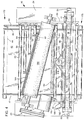
- the invented sander is shown generally at 10 in Figures 1-4.
- Sander 10 is housed in a protective casing 12 and it is controlled by a control panel 14, both of which are shown in dashed lines in Figure 2.
- Casing 12 may be removed to allow for maintenance and repair of the invented sander.
- Casing 12 may also include ports or apertures to access the enclosed structure.
- the invented sander is supported by a frame 16, including a horizontal base support 18 and a plurality of vertical supports 20. In the embodiment shown in the drawings, there are three vertical supports 20 on each side of the sander.
- Frame 16 also includes horizontal support plates 22, 23 and 24. Plates 22 and 23 are connected by vertical support plate 26 and plates 22 and 24 are connected by vertical support plate 28. Plates 26 and 28 are, in turn, connected to vertical supports 20 on their respective sides of the sander. A cross support 30 extends from one side of the sander to the other and connects two of the vertical supports 20.
- Supports 32 and 34 are positioned one on each side of the sander. Extending across the sander between supports 32 and 34 is a horizontal beam 36.
- the invented sander also includes a conveyor belt assembly 40, including a conveyor belt 42 extending around rollers 44 and 46.
- the rollers are connected on one side by support 47 and on the other side by support 48.
- a plate 49 connected to supports 47 and 48, extends between rollers 44 and 46 and under the top surface of belt 42 to support the belt.
- Supports 47 and 48 are mounted to screws 50 by threaded couplings 51.
- Screws 50 are mounted to frame 16 by bearings 52 which allow the screws to rotate.
- the screws are rotated by a motor 54 and a chain 56 driven by the motor which extends around toothed pulleys attached to the screws.
- a hand operated mechanism may be used to raise and lower the conveyor assembly.
- a gauge 58 shown attached to casing 12 in Figure 2, is used to indicate the elevation or height of a product placed on the conveyor belt.
- a wood product such as a cabinet panel
- Rotating screws 50 causes the conveyor belt and the panel to rise and contact the gauge which indicates when the conveyor and panel have reached the desired position.
- Gauge 58 may simply be an analogue dial with a spring-biased point that is pushed up when the conveyor belt assembly and wood panel is raised.
- Conveyor belt 42 is powered by roller 44, which in turn is rotated by a motor 60 and a chain 62 extending between the motor and the roller.
- Motor 60 is mounted to support 48 of the conveyor belt assembly by a mount 63.
- Idler or tensioning gears may be positioned between motor 60 and roller 44 to maintain the appropriate tension on chain 62.
- a belt can be used to drive roller 44.
- Opposed and driven pinch rollers can also be used instead of a conveyor belt.
- stationary guides can be used to hand feed the invented sander.
- Conveyor means is used herein to describe all these structures.
- pinch rollers 64 Positioned above the conveyor belt assembly, and mounted to the frame, are several pinch rollers 64. Products placed on conveyor belt 42 are held in place by pinch rollers 64 as they are fed through the invented sander.
- the invented sander also includes a brace 70, shown best in Figure 1.
- Brace 70 is connected to two drive shafts 72 and 74.
- Drive shaft 72 is shown isolated from other structure in Figure 8.
- shaft 72 includes a step portion 73 that extends away from and then returns to the longitudinal axis 75 of the shaft.
- section 73 orbits around the axis.
- the step in shaft 72 is approximately 4mm or 5/32nds-of-an-inch, creating an orbit with a diameter of 8mm or 5/16ths-of-an-inch.
- Shaft 74 is similar to shaft 72 and brace 70 is mounted to the two shafts around the shafts' stepped portions. Thus, when the shafts are rotated, their stepped portions as well as brace 70 move in an orbit.
- Eccentric cams may be used instead of stepped drive shafts 72 and 74.
- Brace 70 is mounted to shaft 72 by bearings 76 bolted to the brace.
- Shaft 72 is mounted to frame 16 by bearings 78 connected to plate 23 and support 32, as shown in Figure 1.
- Shaft 74 is mounted to plate 24 and support 34 in a similar fashion.
- a motor 80 mounted to one of the vertical supports 20, rotates shaft 72 by a chain 82 extending around a pulley 84 mounted to the motor's drive shaft and a pulley 86 mounted to the lower end of shaft 72.
- a pulley 90 is mounted to the upper end of shaft 72 and a similar pulley 92 is mounted to shaft 74.
- a chain 94 extends around pulleys 90 and 92 and an idler or tensioning gear 96 (shown in Figure 4 only) maintains tension in the chain.
- Motor 80 rotates shaft 72 which in turn rotates shaft 74 by chain 94 extending around pulleys 90 and 92. As stated, rotating shafts 72 and 74 causes brace 70 to move in an orbit or circular pattern.
- the invented sander also includes an orbiting platen 100 shown best in Figures 1, 5 and 6.
- the platen is typically made of aluminum and, as seen in Figures 5 and 6, is generally U-shaped.
- the platen can be of varying widths and lengths. In the preferred embodiment, for example, its length ranges from approximately .5 to 1.5 meters or 24-inches to 49-inches.
- Platen 100 is connected to two drive shafts 102 and 104 by standard flange mount bearings 106 which are bolted to the platen.
- the use of standard flange mount bearings allows for self-alignment of the shafts when they are rotated.
- the invented sander can be constructed with only one shaft supporting the platen but the use of two or more shafts results in greater platen stability.
- Eccentric cams can be used instead of shafts 102 and 104.
- Shaft 102 is shown in Figure 7 isolated from other structure.
- shaft 102 includes a step 108 that extends away from the longitudinal axis 110 of the shaft.
- Step 108 causes a portion 112 of shaft 102 to orbit around the shaft's longitudinal axis when the shaft is rotated.
- step 108 is approximately 1.6mm or 1/16th-of-an-inch, resulting in an orbit having a diameter of approximately 3.2mm or 1/8th-of-an-inch.
- Shaft 104 is identical to shaft 102.
- Shafts 102 and 104 are connected to brace 70 by bearings 114.
- a motor 116 is also connected to brace 70 by a mount 118.
- a timing pulley 120 is mounted to the drive shaft of the engine, a similar timing pulley 122 is mounted to the upper end of shaft 102 and a timing pulley 124 is mounted to the upper end of shaft 104.
- a toothed timing belt 126 extends around pulleys 120, 122 and 124 and rotates shafts 102 and 104 when motor 116 rotates pulley 120. Shafts 102 and 104, in turn, cause platen 100 to orbit or move in a circular pattern.
- the toothed belt and timing pulleys allow for perfect timing between shafts 102 and 104.
- Motor 116 is centered between pulleys 122 and 124 to eliminate the need for idlers on belt 126.
- Disks 130 and 132 are mounted to the lower portions of shafts 102 and 104, respectively, to counterbalance the motion of platen 100.
- Weights 134 are attached to the disks and positioned opposite the step in the shaft to create the necessary counterbalance weight. Weights 134 may be made from nuts, bolts and washers and are therefore adjustable. Holes may be drilled in disks 130 and 132 to accommodate any number of bolts.
- platen 100 moves in two orbits, one created by the rotation of shafts 102 and 104 and the other created by the rotation of brace 70.
- This dual rotation simulates the motion of sanding by hand.
- Shafts 102 and 104 typically rotate at 3,000 to 12,000 revolutions per minute while shafts 72 and 74 typically rotate at approximately 200 revolutions per minute.
- Shafts 102 and 104 may rotate in the same direction or in the opposite direction as shafts 72 and 74.
- Any structure capable of driving the platen and abrasive in one or more orbits may be used such as the motor and drive shaft structure described above.
- the invented sander may alternatively be constructed with only one orbit.
- One orbit allows for a smaller and less expensive machine.
- each stabilizer is secured to brace 70 by a C-clamp 142.
- the C-clamp is made from two opposed, C-shaped parts, 144 and 146, one of which is welded to brace 70.
- a stabilizer is inserted between the two parts which are then bolted together by a bolt such as bolt 148.
- each stabilizer simply rests against the inner surface of platen 100.
- the pressure exerted by each stabilizer against platen 100 can be adjusted by elevator bolts 144.
- Each elevator bolt is similar to a plunger and includes a threaded stud with a flat surface attached to one end. Each bolt is threaded through a tapped hole in brace 70.
- a jam nut 146 and opposed nuts 148 are threaded onto the upper end of each elevator bolt. Loosening jam nut 146 allows for the elevator bolt to be tightened by nuts 148. Tightening the elevator bolt increases the pressure against stabilizer 140 which in turn increases the pressure against platen 100. When the desired pressure is obtained, jam nut 146 is tightened to secure the elevator bolts in position.
- the stabilizers are adjustable to level the platen, cause the platen to apply increased pressure at a certain point, or to compensate for wear. Additionally, the stabilizers maintain the platen level while still allowing it to move in two different orbits. In other words, because stabilizers 140 are made of rubber or synthetic rubber and are therefore partially deformable, platen 100 can remain level while moving in the orbit created by shafts 102 and 104 as well as in the orbit created by shafts 72 and 74.
- a foam pad 150 is attached to the outer, bottom surface of platen 100.
- the pad is typically made from a deformable yet firm foam and is secured to the platen by an adhesive.
- a sponge rubber or a rubber having a light durometer may be used.
- An abrasive 152 is secured to the platen around foam 150.
- Clips 154 are used to secure the abrasive to the platen.
- the abrasive may be secured to the foam and platen by an adhesive. "Secured" means that the abrasive's motion is completely dependent on the platen's motion. Thus, when the platen moves the abrasive also moves.
- the foam is positioned between the platen and the abrasive to provide a soft touch to prevent the abrasive's grit from scratching into a product too deeply. Without the foam, unwanted scratches would result from products that are not perfectly flat.
- a spring-biased rod 160 (shown best in Figures 4-6) is used to operate the clips on the back side of the platen.
- the rod includes a handle 162 and arms 164. When the handle is pushed down, the rod rotates and the arms contact the clips and cause them to open. The rod can then be locked in place by locking mechanism 166. The abrasive is then inserted between the clips and the platen. The clips close when the rod is released. In the preferred embodiment, the rod is secured to brace 70.
- the invented sander includes an upstream or front end 170 and a downstream or back end 172. Downstream from platen 100 is a rotating brush 180 positioned across conveyor belt 42. Brush 180 is supported by frame 16 and driven by a motor 182. Brush 180 removes any remaining streaks or scratches in products such as wood. Scratches removed by the brush are typically less than .002cm or .0005-of-an-inch deep. Brush 180 is angled across conveyor belt 42 so that its bristles contact the wood product at an angle to any remaining cross-grain sanding patterns. Other embodiments of the invented sander may include two or more rotating brushes arranged at 90° relative to each other. Alternatively, the invented sander can be operated without any rotating brush.
- a vacuum 184 (shown only in Figure 4) is positioned upstream and downstream from brush 180 to remove any dust resulting from the sanding.
- Vacuum 184 may be mounted to frame 16 and extend above conveyor belt 42.
- Figure 9 shows an alternative embodiment of the invented sander including two orbiting platens 190 positioned opposite each other.
- An abrasive 192 is secured to the opposed faces of each platen.
- a conveyor belt 194 feeds wood between the two platens, thereby allowing two surfaces of the wood to be abraded simultaneously.
- the platens may be arranged side-by-side in a row.
- conveyor belt 42 is lowered and a product such as a wood panel is placed thereon.
- the belt is then raised until the desired height is obtained. At this point, the wood is positioned between belt 42 and the first pinch roller 64.
- the conveyor belt is then powered so that it feeds or drives the wood product toward platen 100.
- the area immediately beneath platen 100 may be thought of as an abrading area.
- the wood product such as product 174 in Figures 5 and 6 is fed under platen 100 and abraded by abrasive 152.
- Abrasive 152 and platen 100 both move in at least one orbit, substantially eliminating all cross-grain sanding patterns.
- the wood product is then fed past platen 100 where it contacts a second pinch roller.
- the wood product then contacts brush 180 and any remaining scratches or streaks are removed.
- the remaining pinch rollers 64 are supported by a brace (not shown) that extends over the conveyor belt. Those pinch rollers hold the wood product in position as it is conveyed under brush 180.
- the wood is finally emitted from the sander at downstream end 172.
- the invented sander is applicable in any situation where sanding patterns need to be removed from products.
- the invented sander is especially applicable for finish sanding applications such as desk and table tops, panels, doors and cabinets. Additionally, the invented sander is applicable in situations where glass, plastic or metals need to be polished.
Landscapes
- Engineering & Computer Science (AREA)
- Mechanical Engineering (AREA)
- Life Sciences & Earth Sciences (AREA)
- Wood Science & Technology (AREA)
- Finish Polishing, Edge Sharpening, And Grinding By Specific Grinding Devices (AREA)
- Polishing Bodies And Polishing Tools (AREA)
Claims (27)
- Ein umlaufendes Schleifgerät (10) mit einem Rahmen (16), einer Platte (100) sowie einem Schleifmittel (152), welches an der Platte (100) anhaftet, wobei ein Mechanismus sich zwischen der Platte (100) und dem Rahmen (16) befindet und diese miteinander verbindet, dadurch gekennzeichnet, daß der Mechanismus derart ausgebildet ist, daß er eine translatorische Orbitalbewegung einer zweiten Bewegung auf die Platte (100) relativ zum Rahmen (16) überlagert, wobei der Mechanismus einen ersten Motor (116) sowie eine erste (102) und eine zweite (104) Welle umfaßt, die die Platte (100) abstützen, und wobei der erste Motor (116) auf einem Zugglied (70) montiert ist, welches durch den Rahmen (16) abgestützt ist, und wobei die erste (102) und die zweite (104) Welle durch das Zugglied (70) abgestützt sind, und sowohl die erste (102) als auch die zweite (104) Welle an den ersten Motor (116) angeschlossen sind und zeitgleich gedreht werden, und wobei die Rotation der ersten (102) und der zweiten (104) Wellen die erste translatorische Orbitalbewegung auf die Platte (100) übertragen und der zweite Motor (80) an dem Rahmen (16) montiert und an das Zugglied (70) angeschlossen ist und die zweite Bewegung durch den zweiten Motor (80) angetrieben ist.
- Schleifgerät nach Anspruch 1, bei welchem die erste translatorische Bewegung im wesentlichen kreisförmig ist.
- Schleifgerät nach Anspruch 1, bei welchem die Schleifmittelschicht (152) an der Platte (100) durch ein Haftmittel gehalten ist.
- Schleifgerät nach einem der vorangehenden Ansprüche, außerdem mit einer mechanischen Sicherungseinrichtung (154), mittels welcher die Schleifmittelschicht (152) an der Platte (100) gehalten ist.
- Schleifgerät nach einem der vorangehenden Ansprüche, darüber hinaus mit einer Fördereinrichtung (40) angrenzend an die Platte (100).
- Schleifgerät nach einem der vorangehenden Ansprüche, wobei die Platte (100) länglich ausgebildet ist und wobei die Platte sich im wesentlichen quer zur Fördereinrichtung (40) erstreckt.
- Schleifgerät nach einem der vorangehenden Ansprüche, darüber hinaus mit einer rotierenden Bürste (180) angrenzend an die Platte (100).
- Schleifgerät nach Anspruch 7, wobei das Schleifgerät eine Beschickungsrichtung besitzt und die rotierende Bürste (180) in einem Winkel relativ zur Beschickungsrichtung positioniert ist.
- Schleifgerät nach einem der vorangehenden Ansprüche, darüber hinaus mit zwei Taktgeberriemenscheiben (122, 124), einer auf der ersten Welle (102) und einer auf der zweiten Welle (104), sowie mit einem Taktgeberriemen (126), der von dem ersten Motor (116) angetrieben ist und die beiden Taktgeberriemenscheiben (122, 124) umläuft, derart, daß dann, wenn die erste (102) und die zweite (104) Welle durch den ersten Motor (116) gedreht werden, sich die Wellen zeitgleich bewegen.
- Schleifgerät nach Anspruch 9, darüber hinaus mit einer dritten Welle (81), die sich von dem zweiten Motor (80) ausgehend erstreckt, wobei das Zugglied (70) verschiebbar ist und wobei das Zugglied (70) sich bewegt zur Erzeugung der zweiten Bewegung, wenn die dritte Welle (81) durch den zweiten Motor (80) gedreht wird.
- Schleifgerät nach einem der Ansprüche 9 oder 10, darüber hinaus mit einem ersten und einem zweiten Lager (114), die an dem Zugglied (70) montiert sind, sowie einem dritten und einem vierten Lager (106), angrenzend an die Platte (100), wobei das erste und das dritte Lager sowie das zweite und das vierte Lager jeweils die erste bzw. die zweite Welle halten.
- Schleifgerät nach einem der Ansprüche 9 bis 11, darüber hinaus mit einem nachgiebig federnden Stabilisator (140), der sich betrieblich zwischen der Platte (100) und dem Zugglied (70) befindet, zur Stabilisierung der Platte (100).
- Schleifgerät nach Anspruch 12, wobei der nachgiebig federnde Stabilisator (140) einstellbar ist zur Übertragung unterschiedlicher vorbestimmter Drücke auf die Platte (100).
- Schleifgerät nach einem der Ansprüche 9 bis 13, darüber hinaus mit einer vierten (72) und einer fünften (74) Welle, die den Rahmen (16) und das Zugglied (70) miteinander verbinden, wobei die Wellen gedreht werden, wenn die dritte Welle (81) durch den zweiten Motor (80) in Rotation versetzt wird, und wobei die Rotation der vierten (72) und der fünften (74) Welle eine Bewegung des Zuggliedes (70) bewirkt.
- Schleifgerät nach einem der Ansprüche 9 bis 14, wobei die Platte (100) länglich ausgebildet ist, mit einer Mitte und einem ersten und einem zweiten Ende und wobei die erste Welle (102) an die Platte (100) angeschlossen ist zwischen der Plattenmitte und dem ersten Ende, und die zweite Welle (104) an die Platte (100) angeschlossen ist zwischen der Plattenmitte und dem zweiten Ende.
- Schleifgerät nach einem der Ansprüche 9 bis 15, wobei die erste (102) und die zweite (104) Welle abgestuft sind.
- Schleifgerät nach einem der vorangehenden Ansprüche, wobei die Platte eine flache Unterseite besitzt mit Seitenkanten und wobei sich die Schleifmittelschicht über die flache Unterseite der Platte erstreckt sowie über die Seitenkanten.
- Schleifgerät nach einem der vorangehenden Ansprüche, darüber hinaus mit einem Polster, welches auf der Unterseite der Platte gehalten ist, wobei sich die Schleifmittelschicht über das Polster erstreckt.
- Schleifgerät nach einem der vorangehenden Ansprüche, darüber hinaus mit einer zweiten Platte, einer zweiten Schleifmittelschicht, die an der zweiten Platte gehalten ist, sowie einem Antriebsmechanismus zur Bewegung der zweiten Platte und der zweiten Schleifmittelschicht.
- Schleifgerät nach Anspruch 19, wobei die Platten einander gegenüberliegen und einander gegenüberliegende Seiten eines Werkstückes schleifen.
- Schleifgerät nach einem der vorangehenden Ansprüche, wobei die zweite Bewegung eine translatorische Bewegung ist.
- Schleifgerät nach einem der vorangehenden Ansprüche, wobei die zweite Bewegung kreisförmig ist.
- Schleifgerät nach einem der vorangehenden Ansprüche, wobei die erste und die zweite Bewegung mit unterschiedlichen Geschwindigkeiten ablaufen.
- Schleifgerät nach einem der vorangehenden Ansprüche, wobei die erste und die zweite Bewegung unterschiedliche Ausmaße besitzen.
- Schleifgerät nach einem der vorangehenden Ansprüche, wobei das Schleifgerät eine Beschickungsrichtung besitzt und die Bewegungen, die auf die Platte übertragen werden, die Schleifmittelschicht veranlassen sich zu bewegen, und zwar zeitweise in einer ersten Richtung im wesentlichen entgegengesetzt zur Beschickungsrichtung und zeitweise in einer zweiten Richtung im wesentlichen senkrecht zur Beschickungsrichtung.
- Schleifgerät nach einem der vorangehenden Ansprüche, darüber hinaus mit einem Vakuumanschluß zur Entfernung des Staubes, der sich aus dem Schleifvorgang ergibt.
- Schleifgerät nach einem der vorangehenden Ansprüche, darüber hinaus mit einem Vakuum zur Entfernung des Staubes, der sich aus dem Schleifvorgang ergibt.
Applications Claiming Priority (3)
| Application Number | Priority Date | Filing Date | Title |
|---|---|---|---|
| US07/568,902 US5081794A (en) | 1990-08-17 | 1990-08-17 | Sander with orbiting platen and abrasive |
| US568902 | 1990-08-17 | ||
| PCT/US1991/005849 WO1992003257A1 (en) | 1990-08-17 | 1991-08-16 | Sander with orbiting platen and abrasive |
Publications (3)
| Publication Number | Publication Date |
|---|---|
| EP0543947A1 EP0543947A1 (de) | 1993-06-02 |
| EP0543947A4 EP0543947A4 (de) | 1994-02-02 |
| EP0543947B1 true EP0543947B1 (de) | 1999-02-03 |
Family
ID=24273218
Family Applications (1)
| Application Number | Title | Priority Date | Filing Date |
|---|---|---|---|
| EP91917756A Expired - Lifetime EP0543947B1 (de) | 1990-08-17 | 1991-08-16 | Schleifmaschine mit schwingenden platte und schleifmittel |
Country Status (8)
| Country | Link |
|---|---|
| US (4) | US5081794A (de) |
| EP (1) | EP0543947B1 (de) |
| AT (1) | ATE176418T1 (de) |
| AU (1) | AU8714291A (de) |
| CA (1) | CA2089746A1 (de) |
| DE (1) | DE69130864T2 (de) |
| ES (1) | ES2131054T3 (de) |
| WO (1) | WO1992003257A1 (de) |
Cited By (3)
| Publication number | Priority date | Publication date | Assignee | Title |
|---|---|---|---|---|
| WO2004020146A1 (de) * | 2002-08-21 | 2004-03-11 | Heesemann Juergen | Schleifmaschine und verfahren zum schleifen eines werkstücks |
| DE10256124B3 (de) * | 2002-11-29 | 2004-07-15 | Heesemann, Jürgen, Dipl.-Ing. | Bearbeitungsmaschine und Loslageranordnung hierzu |
| EP2380700A2 (de) | 2010-04-23 | 2011-10-26 | Hans Weber Maschinenfabrik GmbH | Portalschleifmaschine |
Families Citing this family (22)
| Publication number | Priority date | Publication date | Assignee | Title |
|---|---|---|---|---|
| US5081794A (en) | 1990-08-17 | 1992-01-21 | Haney Donald E | Sander with orbiting platen and abrasive |
| US7004818B1 (en) * | 1990-08-17 | 2006-02-28 | Haney Donald E | Sander with orbiting platen and abrasive |
| US5707273A (en) * | 1994-04-28 | 1998-01-13 | Timesavers, Inc. | Multiple-pad orbital sander with split pad platen |
| GB9423848D0 (en) * | 1994-11-25 | 1995-01-11 | Black & Decker Inc | Improved oscillating hand tool |
| US5895312A (en) * | 1996-10-30 | 1999-04-20 | International Business Machines Corporation | Apparatus for removing surface irregularities from a flat workpiece |
| US5997386A (en) * | 1997-12-16 | 1999-12-07 | Pridgeon & Clay, Inc. | Automated deburring assembly |
| US6533648B2 (en) * | 1998-10-05 | 2003-03-18 | Edward Drees | Surface preparation device |
| US6200206B1 (en) | 1998-10-05 | 2001-03-13 | Edward Drees | Surface preparation device |
| US6089958A (en) * | 1999-05-13 | 2000-07-18 | Costa; Alessandro | Belt sander with orbitally translated abrasive belt |
| US6299512B1 (en) * | 1999-05-13 | 2001-10-09 | Alessandro Costa | Belt sander with orbitally translated abrasive belt |
| US6244933B1 (en) | 1999-07-07 | 2001-06-12 | Wolfgang Morkvenas | Random orbital finishing apparatus |
| US6086461A (en) * | 1999-10-04 | 2000-07-11 | Harris-Tarkett, Inc. | Wood strip sanding machine |
| US6468140B1 (en) * | 2000-08-14 | 2002-10-22 | Chun-Hsiang Wang | Swinging device for a sanding machine |
| KR20010025366A (ko) * | 2000-12-20 | 2001-04-06 | 김학도 | 자동연마기의 브러시부착용 축 |
| US20040157539A1 (en) * | 2002-07-26 | 2004-08-12 | Stenftenagel John R. | Scuffing machine for finishing wood products |
| ITMO20050254A1 (it) * | 2005-10-06 | 2007-04-07 | Scm Group Spa | Gruppo abrasivo |
| US9056384B1 (en) * | 2014-01-10 | 2015-06-16 | Tacha Holdings Inc. | Apparatus and method for sanding edges of a panel |
| IT201700054727A1 (it) * | 2017-05-19 | 2018-11-19 | Scm Group Spa | Macchina levigatrice perfezionata. |
| CN110303396A (zh) * | 2019-07-15 | 2019-10-08 | 磐安西昂电子有限公司 | 一种木质建材打磨加工系统 |
| CN110695792A (zh) * | 2019-09-23 | 2020-01-17 | 佛山市派特尔机械制造有限公司 | 一种门套板自动砂光机 |
| CN112518518B (zh) * | 2020-11-25 | 2024-01-09 | 内蒙古丰景智造工程技术有限公司 | 一种木质工艺品外表抛光清理装置 |
| CN118699908B (zh) * | 2024-08-30 | 2024-12-20 | 南通惠舜机械制造有限公司 | 一种五金锁具生产用表面高效处理设备 |
Family Cites Families (137)
| Publication number | Priority date | Publication date | Assignee | Title |
|---|---|---|---|---|
| US496052A (en) * | 1893-04-25 | friedel | ||
| US296585A (en) * | 1884-04-08 | Joseph b | ||
| US346680A (en) * | 1886-08-03 | Sand-paper cylinder | ||
| US577582A (en) * | 1897-02-23 | mitchell | ||
| US67240A (en) * | 1867-07-30 | Improvement in machines fob polishing wood | ||
| US449686A (en) * | 1891-04-07 | maleyez | ||
| US513618A (en) * | 1894-01-30 | ofpeemann | ||
| US676487A (en) * | 1900-08-10 | 1901-06-18 | Charles Brown | Abrasive sleeve. |
| US714899A (en) * | 1901-12-30 | 1902-12-02 | Eli B Hayes | Sanding-machine. |
| US1027558A (en) * | 1908-12-05 | 1912-05-28 | Willard F Meyers | Stoneworking-machine. |
| US1143725A (en) * | 1912-11-22 | 1915-06-22 | United Shoe Machinery Ab | Pad-holder. |
| US1166640A (en) * | 1913-08-25 | 1916-01-04 | George S Shaw | Grinding-machine. |
| US1233120A (en) * | 1915-09-22 | 1917-07-10 | Fred R Patch | Grinding and polishing machine. |
| US1494895A (en) * | 1920-03-18 | 1924-05-20 | Foldessy Coleman | Carpet-cleaning machine |
| FR567783A (fr) | 1923-06-23 | 1924-03-10 | Const Et Fonderies De Jeumont | Appareil à dresser et polir les glaces, verres et autres matières |
| FR597948A (fr) * | 1924-03-10 | 1925-12-02 | Machine pour le meulage et le polissage des dalles, tranches, etc. | |
| US1909902A (en) * | 1926-02-01 | 1933-05-16 | Simplex Engineering Company | Glass polishing apparatus |
| US1963357A (en) * | 1931-09-02 | 1934-06-19 | Wingfoot Corp | Abrasive or polishing roll |
| US1962766A (en) * | 1932-03-23 | 1934-06-12 | Libbey Owens Ford Glass Co | Surfacing apparatus |
| US1962357A (en) * | 1932-10-27 | 1934-06-12 | Pro Ker Lab Inc | Means for measuring the growth or production of hair |
| US1988577A (en) * | 1933-01-04 | 1935-01-22 | Scrimgeour William | Abrading machine |
| US1962767A (en) * | 1933-07-03 | 1934-06-12 | Libbey Owens Ford Glass Co | Surfacing apparatus |
| US2192486A (en) * | 1937-09-01 | 1940-03-05 | Shuron Optical Co Inc | Lens grinding and polishing machine |
| US2195065A (en) * | 1938-11-05 | 1940-03-26 | Chrysler Corp | Finishing apparatus and method |
| US2269197A (en) * | 1939-09-20 | 1942-01-06 | Alfred E Hamilton | Grinding and polishing apparatus |
| US2294064A (en) * | 1940-08-04 | 1942-08-25 | Behr Manning Corp | Sanding head |
| US2234109A (en) * | 1940-08-22 | 1941-03-04 | Culpepper James Luther | Abrading device |
| US2286208A (en) * | 1940-12-03 | 1942-06-16 | Carborundum Co | Granular coated article and its manufacture |
| US2311346A (en) * | 1942-03-26 | 1943-02-16 | Adolph T Munn | Sandpapering machine |
| US2579866A (en) * | 1944-08-03 | 1951-12-25 | Minit Man Inc | Motor vehicle cleaning apparatus having rotary brushes mounted on pivoted carriers |
| US2412141A (en) * | 1945-05-07 | 1946-12-03 | Asa J Ford | Mechanical grinding stone |
| US2405328A (en) * | 1945-11-02 | 1946-08-06 | Marsh Wall Products Inc | Sanding machine |
| US2442042A (en) * | 1946-03-19 | 1948-05-25 | Alfred E Hamilton | Grinding apparatus |
| US2447102A (en) * | 1946-12-03 | 1948-08-17 | Alfred G Strand | Sanding disk |
| US2485295A (en) * | 1947-09-17 | 1949-10-18 | Adolph J Larson | Pack of abrasive coated sheets |
| US2553254A (en) * | 1948-09-02 | 1951-05-15 | William B Hays | Sanding tool |
| US2700259A (en) * | 1949-10-10 | 1955-01-25 | Dreyfus Sylvain | Process for treating brush bristles |
| US2644280A (en) * | 1950-09-13 | 1953-07-07 | Carborundum Co | Sanding disk accessory |
| US2606947A (en) * | 1950-10-25 | 1952-08-12 | Singer Mfg Co | Electric motor for sanding tools or the like |
| BE511644A (de) * | 1951-05-24 | |||
| US2641878A (en) * | 1951-07-27 | 1953-06-16 | John M Radabaugh | Abrading unit |
| US2690036A (en) * | 1953-08-14 | 1954-09-28 | Baldridge Ronald | Lapping machine |
| US2729037A (en) * | 1953-10-19 | 1956-01-03 | Dom D Soccoli | Abrasive holder |
| FR1085718A (fr) * | 1953-10-28 | 1955-02-07 | Peugeot & Cie | Machine à mouvement rotatif de faible amplitude commandé par excentrique |
| US2751725A (en) * | 1954-08-13 | 1956-06-26 | Roy J Champayne | Orbital action rubbing machine |
| US2909871A (en) * | 1955-09-08 | 1959-10-27 | Saint Gobain | Apparatus for polishing glass and the like |
| US2949707A (en) * | 1956-02-23 | 1960-08-23 | David H Staelin | Method and apparatus for grinding and polishing sheet glass |
| US2842904A (en) * | 1956-04-30 | 1958-07-15 | Leavitt Machine Co | Grinding head and grinding surface therefor |
| US2945330A (en) * | 1957-01-17 | 1960-07-19 | Saint Gobain | Apparatus for surfacing glass |
| US2843980A (en) * | 1957-04-08 | 1958-07-22 | Merit Products Inc | Abrasive wheel and replaceable abrasive unit therefor |
| BE566697A (de) * | 1957-04-11 | |||
| US2926465A (en) * | 1957-09-05 | 1960-03-01 | Edward S Sommers | Oscillating belt sanders |
| US2985989A (en) * | 1958-07-15 | 1961-05-30 | Lloyd H Knost | Slab surfacing machine |
| US3026653A (en) * | 1958-11-03 | 1962-03-27 | Zordo Battista De | Automatic machine for lapping of marble slabs and other similar stones |
| US3006116A (en) * | 1959-02-17 | 1961-10-31 | Lloyd H Knost | Apparatus for honing hard surfaced materials |
| US2989823A (en) * | 1959-03-09 | 1961-06-27 | Merit Products Inc | Finishing machine with reciprocative rotary finishing roll |
| US2983083A (en) * | 1959-03-23 | 1961-05-09 | Nat Gypsum Co | Method of forming patterned tile and apparatus therefor |
| US3263376A (en) * | 1959-12-16 | 1966-08-02 | Libbey Owens Ford Glass Co | Method for surfacing glass |
| US3104503A (en) * | 1961-01-09 | 1963-09-24 | Singer Co | Sander plate assembly for portable sanding tools |
| US3079734A (en) * | 1961-04-14 | 1963-03-05 | Yates American Machine Co | Vibrator mechanism for belt sander |
| SU143370A1 (ru) | 1961-05-18 | 1961-11-30 | А.И. Минаев | Нижнее распределительное устройство дл водоподготовительных фильтров |
| US3107456A (en) * | 1961-09-14 | 1963-10-22 | Libbey Owens Ford Glass Co | Apparatus for surfacing glass |
| US3094815A (en) * | 1961-10-02 | 1963-06-25 | Raymond F Pendergast | Polishing apparatus |
| US3106806A (en) * | 1962-04-02 | 1963-10-15 | Alma A Hutchins | Work smoothing tool |
| US3203074A (en) * | 1962-06-04 | 1965-08-31 | Litton Systems Inc | Sheet clamping arrangements |
| US3267623A (en) * | 1963-02-08 | 1966-08-23 | Merit Products Inc | Abrasive article |
| US3271909A (en) * | 1964-03-13 | 1966-09-13 | Carborundum Co | Grinding apparatus |
| FR1407163A (fr) * | 1964-06-16 | 1965-07-30 | Saint Gobain | Perfectionnement aux outils pour le doucissage et le polissage des surfaces |
| FR1409372A (fr) * | 1964-07-15 | 1965-08-27 | Saint Gobain | Perfectionnement aux dispositifs pour le doucissage ou le polissage des feuilles de verre |
| US3339319A (en) * | 1964-10-29 | 1967-09-05 | Timesavers Sanders | Abrasive sleeve for rotary abrading machines |
| US3543449A (en) * | 1965-01-11 | 1970-12-01 | Murphy Ind Inc G W | Dual motion surface-dressing machine |
| US3416261A (en) * | 1966-10-19 | 1968-12-17 | Us Plywood Corp | Sanding and polishing machine |
| US3522680A (en) * | 1967-03-23 | 1970-08-04 | George M J Sarofeen | Expanded metal facing for a lens abrading tool |
| DE1556287A1 (de) * | 1967-12-09 | 1970-02-05 | Walter Tilleke | Transportvorrichtung |
| DE1938477C3 (de) | 1968-08-10 | 1980-10-23 | Luciano Lecco Como Bernasconi (Italien) | Maschine zum Flachschleifen und/oder -Polieren von Werkstücken aus nichtmetallischen, anorganischen Werkstoffen, wie beispielsweise Granit, Marmor u.dgl |
| US3533193A (en) * | 1968-11-25 | 1970-10-13 | Singer Co | Dual motion pad sanders |
| US3608245A (en) * | 1969-09-04 | 1971-09-28 | Timesavers Sanders | Belt sanding machine |
| US3654738A (en) * | 1970-09-11 | 1972-04-11 | Timesavers Sanders | Method of and apparatus for effecting superior sanding |
| US3704559A (en) * | 1971-02-11 | 1972-12-05 | Andrew Morgan | Power sander attachment |
| US3708817A (en) * | 1971-03-24 | 1973-01-09 | Timesavers Inc | Buffing and deburring machine |
| US3734700A (en) * | 1971-05-10 | 1973-05-22 | T Gutierrez | Article abrading apparatus |
| US3754354A (en) * | 1971-09-23 | 1973-08-28 | R Franlinna | Grinding device |
| US3701219A (en) * | 1972-01-14 | 1972-10-31 | Timesavers Inc | Apparatus for effecting superior sanding |
| FR2177245A5 (de) * | 1972-03-22 | 1973-11-02 | Garin Maurice | |
| US3832807A (en) * | 1972-06-26 | 1974-09-03 | Timesavers Inc | Wide belt sanding machine with improved work feeding means |
| US3844069A (en) * | 1972-08-15 | 1974-10-29 | L Shank | Automatic loading mechanism and grinding machine |
| US3906678A (en) * | 1972-09-14 | 1975-09-23 | Buehler Ltd | Automatic specimen polishing machine and method |
| US3857206A (en) * | 1973-03-08 | 1974-12-31 | Nat Detroit Inc Co | Compound motion rubbing machine |
| US3859758A (en) * | 1973-06-07 | 1975-01-14 | Timesavers Inc | Wide belt sanding machine |
| US3847271A (en) * | 1973-08-09 | 1974-11-12 | D Culley | Sander with improved feed mechanism |
| US3893265A (en) * | 1974-10-02 | 1975-07-08 | Timesavers Inc | Vertical abrasive belt type surface grinder |
| US3892091A (en) * | 1974-10-17 | 1975-07-01 | Alma A Hutchins | Abrading tool utilizing a self adhesive abrading sheet |
| US4267195A (en) * | 1976-09-10 | 1981-05-12 | University Of Texas | Dog food flavors |
| DE2740696A1 (de) * | 1977-09-09 | 1979-03-15 | Steinbearbeitungs Maschinenfab | Verfahren und vorrichtung zum schleifen oder polieren von steinflaechen |
| JPS5493288A (en) * | 1977-12-31 | 1979-07-24 | Bando Kiko Co | Glass chamfering machine |
| NL7902493A (nl) * | 1979-03-30 | 1980-10-02 | Linden Bv Machine | Schuurinrichting. |
| US4277915A (en) * | 1979-07-06 | 1981-07-14 | Hausermann Abrading & Process Co. | Apparatus for shaping electrodes |
| US4344113A (en) * | 1979-12-18 | 1982-08-10 | Donald R. Ditto | Apparatus to illuminate a liquid drink |
| SU905004A1 (ru) | 1980-04-30 | 1982-02-15 | Всесоюзный Государственный Проектно-Конструкторский Институт "Гипростроммашина" | Устройство дл обработки камн |
| US4399637A (en) * | 1981-01-23 | 1983-08-23 | Acrometal Products, Inc. | Abrasive grinding machine |
| DE3242095C2 (de) * | 1982-11-13 | 1986-02-20 | Ernst Thielenhaus KG, 5600 Wuppertal | Schleifmaschine für das Feinschleifen einer Kurbelwelle |
| EP0118606B1 (de) * | 1982-12-21 | 1989-04-12 | Werner Dr. Ullmann | Maschine zur Herstellung einer Elektrode einer bestimmten Raumform mittels eines Formenschleif-Werkzeuges |
| IT1193685B (it) | 1983-02-25 | 1988-07-21 | Ermanno Pacini | Levigatrice continua a nastro trasportatore per superfici solide,particolarmente adatta per lastre di materiali lapidei |
| US4646473A (en) * | 1984-05-08 | 1987-03-03 | Udviklingscentret Hansen | Method and apparatus for finishing surfaces |
| US4635405A (en) * | 1983-05-18 | 1987-01-13 | Timesavers, Inc. | Continuous arcuate feed assembly |
| DE3319925C1 (de) * | 1983-06-01 | 1984-07-12 | Bayerische Motoren Werke AG, 8000 München | Spannvorichtung zum Halten eines Schleifblattes mit Befestigungslaschen an einem drehbaren Schleifteller |
| SU1242339A1 (ru) | 1983-07-04 | 1986-07-07 | Челябинский Политехнический Институт Им.Ленинского Комсомола | Устройство дл шлифовани неметаллических материалов |
| SU1138297A1 (ru) | 1983-08-15 | 1985-02-07 | Zhukov Valerian A | Шлифовально-полировальный станок дл обработки камн |
| US4667447A (en) * | 1983-08-31 | 1987-05-26 | Minnesota Mining And Manufacturing Company | Coated abrasive sheet material magnetically attached to a support surface on an abrading tool |
| IT1169618B (it) * | 1983-10-27 | 1987-06-03 | Dmc Div Mecc Cast | Macchina levigatrice per pannelli di legno |
| US4475317A (en) * | 1983-11-28 | 1984-10-09 | The Singer Company | Paper retainer for a sanding device |
| US4651474A (en) * | 1984-08-24 | 1987-03-24 | Timesavers, Inc. | Wide belt sanding machine with platen oscillating means |
| US4656788A (en) * | 1984-09-06 | 1987-04-14 | Extrude Hone Corporation | Variable orbital drive mechanism |
| US4733500A (en) * | 1985-07-11 | 1988-03-29 | Timesavers, Inc. | Wood surface treatment method and system employing tandemly oriented cross-belts and rotary abraders |
| US4837984A (en) * | 1985-07-11 | 1989-06-13 | Timesavers, Inc. | Wood surface treatment method and system employing tandemly oriented cross-belts and rotary abraders |
| GB8522441D0 (en) | 1985-09-10 | 1985-10-16 | Lindsey A F | Flat glass |
| US4627195A (en) * | 1985-09-18 | 1986-12-09 | The United States Of America As Represented By The Secretary Of The Air Force | Computer controller optical surfacing (CCOS) lap pressure control system |
| US4720940A (en) * | 1985-09-23 | 1988-01-26 | Green Gary L | Rotary drum sander |
| DE3609441A1 (de) | 1986-03-20 | 1987-09-24 | Bosch Gmbh Robert | Exzenterschleifer mit einer vorrichtung zum veraendern der schleifbewegung |
| US4788798A (en) * | 1986-03-24 | 1988-12-06 | Ferro Corporation | Adhesive system for maintaining flexible workpiece to a rigid substrate |
| DE3615799C2 (de) | 1986-05-10 | 1994-10-13 | Bosch Gmbh Robert | Exzenterschleifer mit einer Vorrichtung zum Verändern der Schleifbewegung |
| DE3630155A1 (de) | 1986-09-04 | 1988-03-10 | Licentia Gmbh | Schwingschleifer mit einer ueber elastische elemente abgestuetzten schleifplatte |
| US4742650A (en) * | 1986-11-07 | 1988-05-10 | Conestoga Wood Specialities, Inc. | Sanding machine |
| US4787178A (en) * | 1987-04-13 | 1988-11-29 | Creative Glassworks International, Inc. | Fluid-jet cutting apparatus |
| US4798025A (en) * | 1987-06-29 | 1989-01-17 | Minnesota Mining And Manufacturing Company | Abrasive disc support |
| US4878317A (en) * | 1987-07-10 | 1989-11-07 | Ovens Melvin L | Power sander |
| SU1546236A1 (ru) | 1987-08-18 | 1990-02-28 | Всесоюзный Государственный Проектно-Конструкторский Институт По Машинам Для Промышленности Строительных Материалов "Гипростроммашина" | Шлифовально-полировальный станок |
| US4891916A (en) * | 1987-10-13 | 1990-01-09 | Extrude Hone Corporation | Oscillatory or translational table for machine tools |
| SU1569190A1 (ru) | 1988-02-16 | 1990-06-07 | Проектно-технологический трест "Оргтехстрой" | Плоскошлифовальна машина |
| DE3809930A1 (de) | 1988-03-24 | 1989-10-05 | Bosch Gmbh Robert | Exzenterschleifer |
| JPH01246059A (ja) * | 1988-03-25 | 1989-10-02 | Cmk Corp | 平面部材の表面研磨装置 |
| US4864775A (en) * | 1988-05-16 | 1989-09-12 | Timesavers, Inc. | Cross-belt sanding machine with oscillating platen means |
| DE8808679U1 (de) * | 1988-07-06 | 1988-11-17 | Wallin, Anders, Lund | Schleifkopf zum Oberflächenbearbeiten und Polieren von Stein, Marmor und anderen harten Werkstoffen |
| NL8802627A (nl) * | 1988-10-25 | 1990-05-16 | Linden Machines Bv | Roterende polijst- of ontbraamplaat. |
| US5018314A (en) | 1989-06-08 | 1991-05-28 | Makita Electric Works, Ltd. | Sander |
| DE8912042U1 (de) * | 1989-10-10 | 1989-11-23 | Kreipe, Herbert, 4930 Detmold | Maschine zum Bearbeiten von Werkstückflächen |
| US5081794A (en) | 1990-08-17 | 1992-01-21 | Haney Donald E | Sander with orbiting platen and abrasive |
-
1990
- 1990-08-17 US US07/568,902 patent/US5081794A/en not_active Expired - Lifetime
-
1991
- 1991-08-16 AU AU87142/91A patent/AU8714291A/en not_active Abandoned
- 1991-08-16 EP EP91917756A patent/EP0543947B1/de not_active Expired - Lifetime
- 1991-08-16 ES ES91917756T patent/ES2131054T3/es not_active Expired - Lifetime
- 1991-08-16 WO PCT/US1991/005849 patent/WO1992003257A1/en not_active Ceased
- 1991-08-16 CA CA002089746A patent/CA2089746A1/en not_active Abandoned
- 1991-08-16 DE DE69130864T patent/DE69130864T2/de not_active Expired - Lifetime
- 1991-08-16 AT AT91917756T patent/ATE176418T1/de not_active IP Right Cessation
-
1993
- 1993-01-19 US US08/006,379 patent/US5321913A/en not_active Expired - Lifetime
-
1994
- 1994-06-15 US US08/260,360 patent/US5443414A/en not_active Expired - Lifetime
-
1995
- 1995-06-07 US US08/477,069 patent/US5702287A/en not_active Expired - Lifetime
Cited By (6)
| Publication number | Priority date | Publication date | Assignee | Title |
|---|---|---|---|---|
| WO2004020146A1 (de) * | 2002-08-21 | 2004-03-11 | Heesemann Juergen | Schleifmaschine und verfahren zum schleifen eines werkstücks |
| DE10256124B3 (de) * | 2002-11-29 | 2004-07-15 | Heesemann, Jürgen, Dipl.-Ing. | Bearbeitungsmaschine und Loslageranordnung hierzu |
| US7381115B2 (en) | 2002-11-29 | 2008-06-03 | Heesemann Juergen | Processing machine and floating-bearing arrangement for it |
| EP2380700A2 (de) | 2010-04-23 | 2011-10-26 | Hans Weber Maschinenfabrik GmbH | Portalschleifmaschine |
| DE102010016606A1 (de) | 2010-04-23 | 2011-10-27 | Hans Weber Maschinenfabrik Gmbh | Schleifmaschine |
| US8475232B2 (en) | 2010-04-23 | 2013-07-02 | Hans Weber Maschinenfabrik Gmbh | Grinding machine |
Also Published As
| Publication number | Publication date |
|---|---|
| ATE176418T1 (de) | 1999-02-15 |
| AU8714291A (en) | 1992-03-17 |
| ES2131054T3 (es) | 1999-07-16 |
| EP0543947A1 (de) | 1993-06-02 |
| US5081794A (en) | 1992-01-21 |
| CA2089746A1 (en) | 1992-02-18 |
| DE69130864T2 (de) | 1999-09-09 |
| EP0543947A4 (de) | 1994-02-02 |
| US5443414A (en) | 1995-08-22 |
| WO1992003257A1 (en) | 1992-03-05 |
| DE69130864D1 (de) | 1999-03-18 |
| US5321913A (en) | 1994-06-21 |
| US5702287A (en) | 1997-12-30 |
Similar Documents
| Publication | Publication Date | Title |
|---|---|---|
| EP0543947B1 (de) | Schleifmaschine mit schwingenden platte und schleifmittel | |
| US7198557B2 (en) | Sanding machine incorporating multiple sanding motions | |
| EP1053827B1 (de) | Bandschleifmaschine mit um eine Umlaufbahn bewegtem Schleifband | |
| US6299512B1 (en) | Belt sander with orbitally translated abrasive belt | |
| US4364696A (en) | Edge finishing machine | |
| US3708817A (en) | Buffing and deburring machine | |
| US5181342A (en) | Sander with orbiting platen and abrasive | |
| FI106540B (fi) | Läpisyöttöhiomakone, joka on erityisesti suunniteltu paneloitujen puupintojen jne. ja paneelien välissä sijaitsevien lakattujen pintojen hiomiseen, pääasiassa tasapintaisissa työkappaleissa | |
| US4864775A (en) | Cross-belt sanding machine with oscillating platen means | |
| EP1708850B1 (de) | Schleifvorrichtung zur behandlung einer oberfläche | |
| US4651474A (en) | Wide belt sanding machine with platen oscillating means | |
| US4733500A (en) | Wood surface treatment method and system employing tandemly oriented cross-belts and rotary abraders | |
| US3153306A (en) | Belt abrader | |
| US4837984A (en) | Wood surface treatment method and system employing tandemly oriented cross-belts and rotary abraders | |
| US7004818B1 (en) | Sander with orbiting platen and abrasive | |
| US6244933B1 (en) | Random orbital finishing apparatus | |
| US20010031614A1 (en) | Random orbital finishing apparatus | |
| US3269065A (en) | Sanding apparatus | |
| US9056384B1 (en) | Apparatus and method for sanding edges of a panel | |
| GB2386332A (en) | Adjustable position belt grinding machine | |
| US3178860A (en) | Multiple sanding and polishing machine | |
| CA2000224A1 (en) | Edge sander having adjustable support table or tables | |
| US747699A (en) | Universal sanding-machine. | |
| CA2348681C (en) | Belt sander with orbitally translated abrasive belt | |
| US3611643A (en) | Planing machine using rotatable abrasive drums |
Legal Events
| Date | Code | Title | Description |
|---|---|---|---|
| PUAI | Public reference made under article 153(3) epc to a published international application that has entered the european phase |
Free format text: ORIGINAL CODE: 0009012 |
|
| 17P | Request for examination filed |
Effective date: 19930216 |
|
| AK | Designated contracting states |
Kind code of ref document: A1 Designated state(s): AT BE CH DE DK ES FR GB IT LI NL SE |
|
| A4 | Supplementary search report drawn up and despatched |
Effective date: 19931214 |
|
| AK | Designated contracting states |
Kind code of ref document: A4 Designated state(s): AT BE CH DE DK ES FR GB IT LI NL SE |
|
| 17Q | First examination report despatched |
Effective date: 19941004 |
|
| GRAG | Despatch of communication of intention to grant |
Free format text: ORIGINAL CODE: EPIDOS AGRA |
|
| GRAG | Despatch of communication of intention to grant |
Free format text: ORIGINAL CODE: EPIDOS AGRA |
|
| GRAH | Despatch of communication of intention to grant a patent |
Free format text: ORIGINAL CODE: EPIDOS IGRA |
|
| GRAH | Despatch of communication of intention to grant a patent |
Free format text: ORIGINAL CODE: EPIDOS IGRA |
|
| GRAA | (expected) grant |
Free format text: ORIGINAL CODE: 0009210 |
|
| AK | Designated contracting states |
Kind code of ref document: B1 Designated state(s): AT BE CH DE DK ES FR GB IT LI NL SE |
|
| PG25 | Lapsed in a contracting state [announced via postgrant information from national office to epo] |
Ref country code: AT Free format text: LAPSE BECAUSE OF FAILURE TO SUBMIT A TRANSLATION OF THE DESCRIPTION OR TO PAY THE FEE WITHIN THE PRESCRIBED TIME-LIMIT Effective date: 19990203 Ref country code: NL Free format text: LAPSE BECAUSE OF FAILURE TO SUBMIT A TRANSLATION OF THE DESCRIPTION OR TO PAY THE FEE WITHIN THE PRESCRIBED TIME-LIMIT Effective date: 19990203 Ref country code: BE Free format text: LAPSE BECAUSE OF FAILURE TO SUBMIT A TRANSLATION OF THE DESCRIPTION OR TO PAY THE FEE WITHIN THE PRESCRIBED TIME-LIMIT Effective date: 19990203 Ref country code: SE Free format text: THE PATENT HAS BEEN ANNULLED BY A DECISION OF A NATIONAL AUTHORITY Effective date: 19990203 Ref country code: LI Free format text: LAPSE BECAUSE OF FAILURE TO SUBMIT A TRANSLATION OF THE DESCRIPTION OR TO PAY THE FEE WITHIN THE PRESCRIBED TIME-LIMIT Effective date: 19990203 Ref country code: FR Free format text: LAPSE BECAUSE OF FAILURE TO SUBMIT A TRANSLATION OF THE DESCRIPTION OR TO PAY THE FEE WITHIN THE PRESCRIBED TIME-LIMIT Effective date: 19990203 Ref country code: CH Free format text: LAPSE BECAUSE OF FAILURE TO SUBMIT A TRANSLATION OF THE DESCRIPTION OR TO PAY THE FEE WITHIN THE PRESCRIBED TIME-LIMIT Effective date: 19990203 |
|
| REF | Corresponds to: |
Ref document number: 176418 Country of ref document: AT Date of ref document: 19990215 Kind code of ref document: T |
|
| REG | Reference to a national code |
Ref country code: CH Ref legal event code: EP |
|
| REF | Corresponds to: |
Ref document number: 69130864 Country of ref document: DE Date of ref document: 19990318 |
|
| ITF | It: translation for a ep patent filed | ||
| PG25 | Lapsed in a contracting state [announced via postgrant information from national office to epo] |
Ref country code: DK Free format text: LAPSE BECAUSE OF FAILURE TO SUBMIT A TRANSLATION OF THE DESCRIPTION OR TO PAY THE FEE WITHIN THE PRESCRIBED TIME-LIMIT Effective date: 19990503 |
|
| NLV1 | Nl: lapsed or annulled due to failure to fulfill the requirements of art. 29p and 29m of the patents act | ||
| EN | Fr: translation not filed | ||
| REG | Reference to a national code |
Ref country code: ES Ref legal event code: FG2A Ref document number: 2131054 Country of ref document: ES Kind code of ref document: T3 |
|
| REG | Reference to a national code |
Ref country code: CH Ref legal event code: PL |
|
| PLBE | No opposition filed within time limit |
Free format text: ORIGINAL CODE: 0009261 |
|
| STAA | Information on the status of an ep patent application or granted ep patent |
Free format text: STATUS: NO OPPOSITION FILED WITHIN TIME LIMIT |
|
| 26N | No opposition filed | ||
| REG | Reference to a national code |
Ref country code: GB Ref legal event code: IF02 |
|
| PGFP | Annual fee paid to national office [announced via postgrant information from national office to epo] |
Ref country code: ES Payment date: 20100810 Year of fee payment: 20 |
|
| PGFP | Annual fee paid to national office [announced via postgrant information from national office to epo] |
Ref country code: DE Payment date: 20100920 Year of fee payment: 20 Ref country code: IT Payment date: 20100824 Year of fee payment: 20 |
|
| PGFP | Annual fee paid to national office [announced via postgrant information from national office to epo] |
Ref country code: GB Payment date: 20100825 Year of fee payment: 20 |
|
| REG | Reference to a national code |
Ref country code: DE Ref legal event code: R071 Ref document number: 69130864 Country of ref document: DE |
|
| REG | Reference to a national code |
Ref country code: DE Ref legal event code: R071 Ref document number: 69130864 Country of ref document: DE |
|
| REG | Reference to a national code |
Ref country code: GB Ref legal event code: PE20 Expiry date: 20110815 |
|
| PG25 | Lapsed in a contracting state [announced via postgrant information from national office to epo] |
Ref country code: GB Free format text: LAPSE BECAUSE OF EXPIRATION OF PROTECTION Effective date: 20110815 |
|
| PG25 | Lapsed in a contracting state [announced via postgrant information from national office to epo] |
Ref country code: DE Free format text: LAPSE BECAUSE OF EXPIRATION OF PROTECTION Effective date: 20110817 |
|
| REG | Reference to a national code |
Ref country code: ES Ref legal event code: FD2A Effective date: 20130725 |
|
| PG25 | Lapsed in a contracting state [announced via postgrant information from national office to epo] |
Ref country code: ES Free format text: LAPSE BECAUSE OF EXPIRATION OF PROTECTION Effective date: 20110817 |