EP0545334A2 - Dispositif pour produire une émulsion gazole-eau - Google Patents
Dispositif pour produire une émulsion gazole-eau Download PDFInfo
- Publication number
- EP0545334A2 EP0545334A2 EP92120388A EP92120388A EP0545334A2 EP 0545334 A2 EP0545334 A2 EP 0545334A2 EP 92120388 A EP92120388 A EP 92120388A EP 92120388 A EP92120388 A EP 92120388A EP 0545334 A2 EP0545334 A2 EP 0545334A2
- Authority
- EP
- European Patent Office
- Prior art keywords
- connection
- emulsifying device
- water
- diesel fuel
- channel
- Prior art date
- Legal status (The legal status is an assumption and is not a legal conclusion. Google has not performed a legal analysis and makes no representation as to the accuracy of the status listed.)
- Granted
Links
Images


Classifications
-
- F—MECHANICAL ENGINEERING; LIGHTING; HEATING; WEAPONS; BLASTING
- F02—COMBUSTION ENGINES; HOT-GAS OR COMBUSTION-PRODUCT ENGINE PLANTS
- F02M—SUPPLYING COMBUSTION ENGINES IN GENERAL WITH COMBUSTIBLE MIXTURES OR CONSTITUENTS THEREOF
- F02M25/00—Engine-pertinent apparatus for adding non-fuel substances or small quantities of secondary fuel to combustion-air, main fuel or fuel-air mixture
- F02M25/022—Adding fuel and water emulsion, water or steam
- F02M25/0228—Adding fuel and water emulsion
-
- B—PERFORMING OPERATIONS; TRANSPORTING
- B01—PHYSICAL OR CHEMICAL PROCESSES OR APPARATUS IN GENERAL
- B01F—MIXING, e.g. DISSOLVING, EMULSIFYING OR DISPERSING
- B01F25/00—Flow mixers; Mixers for falling materials, e.g. solid particles
- B01F25/10—Mixing by creating a vortex flow, e.g. by tangential introduction of flow components
-
- C—CHEMISTRY; METALLURGY
- C10—PETROLEUM, GAS OR COKE INDUSTRIES; TECHNICAL GASES CONTAINING CARBON MONOXIDE; FUELS; LUBRICANTS; PEAT
- C10L—FUELS NOT OTHERWISE PROVIDED FOR; NATURAL GAS; SYNTHETIC NATURAL GAS OBTAINED BY PROCESSES NOT COVERED BY SUBCLASSES C10G OR C10K; LIQUIFIED PETROLEUM GAS; USE OF ADDITIVES TO FUELS OR FIRES; FIRE-LIGHTERS
- C10L1/00—Liquid carbonaceous fuels
- C10L1/32—Liquid carbonaceous fuels consisting of coal-oil suspensions or aqueous emulsions or oil emulsions
- C10L1/328—Oil emulsions containing water or any other hydrophilic phase
-
- F—MECHANICAL ENGINEERING; LIGHTING; HEATING; WEAPONS; BLASTING
- F02—COMBUSTION ENGINES; HOT-GAS OR COMBUSTION-PRODUCT ENGINE PLANTS
- F02B—INTERNAL-COMBUSTION PISTON ENGINES; COMBUSTION ENGINES IN GENERAL
- F02B47/00—Methods of operating engines involving adding non-fuel substances or anti-knock agents to combustion air, fuel, or fuel-air mixtures of engines
- F02B47/02—Methods of operating engines involving adding non-fuel substances or anti-knock agents to combustion air, fuel, or fuel-air mixtures of engines the substances being water or steam
-
- F—MECHANICAL ENGINEERING; LIGHTING; HEATING; WEAPONS; BLASTING
- F02—COMBUSTION ENGINES; HOT-GAS OR COMBUSTION-PRODUCT ENGINE PLANTS
- F02M—SUPPLYING COMBUSTION ENGINES IN GENERAL WITH COMBUSTIBLE MIXTURES OR CONSTITUENTS THEREOF
- F02M25/00—Engine-pertinent apparatus for adding non-fuel substances or small quantities of secondary fuel to combustion-air, main fuel or fuel-air mixture
- F02M25/022—Adding fuel and water emulsion, water or steam
- F02M25/0221—Details of the water supply system, e.g. pumps or arrangement of valves
- F02M25/0225—Water atomisers or mixers, e.g. using ultrasonic waves
-
- B—PERFORMING OPERATIONS; TRANSPORTING
- B01—PHYSICAL OR CHEMICAL PROCESSES OR APPARATUS IN GENERAL
- B01F—MIXING, e.g. DISSOLVING, EMULSIFYING OR DISPERSING
- B01F2101/00—Mixing characterised by the nature of the mixed materials or by the application field
- B01F2101/505—Mixing fuel and water or other fluids to obtain liquid fuel emulsions
-
- B—PERFORMING OPERATIONS; TRANSPORTING
- B01—PHYSICAL OR CHEMICAL PROCESSES OR APPARATUS IN GENERAL
- B01F—MIXING, e.g. DISSOLVING, EMULSIFYING OR DISPERSING
- B01F23/00—Mixing according to the phases to be mixed, e.g. dispersing or emulsifying
- B01F23/40—Mixing liquids with liquids; Emulsifying
- B01F23/41—Emulsifying
-
- F—MECHANICAL ENGINEERING; LIGHTING; HEATING; WEAPONS; BLASTING
- F02—COMBUSTION ENGINES; HOT-GAS OR COMBUSTION-PRODUCT ENGINE PLANTS
- F02B—INTERNAL-COMBUSTION PISTON ENGINES; COMBUSTION ENGINES IN GENERAL
- F02B3/00—Engines characterised by air compression and subsequent fuel addition
- F02B3/06—Engines characterised by air compression and subsequent fuel addition with compression ignition
-
- Y—GENERAL TAGGING OF NEW TECHNOLOGICAL DEVELOPMENTS; GENERAL TAGGING OF CROSS-SECTIONAL TECHNOLOGIES SPANNING OVER SEVERAL SECTIONS OF THE IPC; TECHNICAL SUBJECTS COVERED BY FORMER USPC CROSS-REFERENCE ART COLLECTIONS [XRACs] AND DIGESTS
- Y02—TECHNOLOGIES OR APPLICATIONS FOR MITIGATION OR ADAPTATION AGAINST CLIMATE CHANGE
- Y02T—CLIMATE CHANGE MITIGATION TECHNOLOGIES RELATED TO TRANSPORTATION
- Y02T10/00—Road transport of goods or passengers
- Y02T10/10—Internal combustion engine [ICE] based vehicles
- Y02T10/12—Improving ICE efficiencies
Definitions
- the invention relates to an emulsifying device according to the preamble of claim 1.
- Emulsions of diesel oil and tap water produced with such devices are supplied to the engine of a motor vehicle via already existing injection systems.
- the advantage of such devices lies in their simple structure. Refueling is no more complicated than when injecting non-emulsified diesel fuel.
- the mixing ratio is generally controlled electronically. In this way, emulsions of variable water content can be produced and fed to the engine according to the current load and speed.
- a very decisive advantage of using diesel fuel-water emulsions is the reduction of nitrogen oxides and soot emissions.
- the swirling necessary to prepare the emulsion should take place without the aid of mechanical (rotating) elements; foaming should be avoided; the emulsion should be generated where it is actually needed, ie as close as possible to the area around the injection pump; the amount of emulsion should be adaptable to the consumption of the engine; the emulsion should be rich or lean according to engine performance; for this it is above all necessary to control the water content in a sensitive manner in accordance with the respective operating conditions;
- the construction cost of the device should be kept as low as possible in order to keep the manufacturing costs low.
- the volume of the emulsion produced with known devices is relatively large, which leads to inaccuracies in the metered amount if the load ranges change frequently.
- the required amount of emulsifier must be generated in stock.
- the invention has for its object to design an emulsifying device according to the preamble of claim 1 such that the mixing of diesel fuel and water is as perfect as possible.
- the droplet size should be reduced, any foaming should be avoided, and any moving internals avoided are and the construction and thus the manufacturing costs compared to known devices can be reduced.
- Fig. 1 shows an emulsifying device in a sectional view.
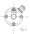
- FIG. 2 shows a top view of the left-hand end face of the device.
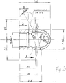
- Fig. 3 shows on an enlarged scale the right of the two hollow bodies, which is located in the mixing chamber of the device.
- FIG. 4 shows a view along the section line A-A in FIG. 3.
- the emulsifying device has a housing 1 in detail. This is divided into two sub-housings 1.1, 1.2.
- the housing encloses a mixing chamber with inner wall surfaces 2.
- Housing part 1.1 has a connection bore 3 which receives a water injection nozzle 4.
- a connection 5.1 is provided in the housing part 1.1 for supplying diesel fuel.
- Housing part 1.2 has a threaded bore 7.
- a fitting 8 for discharging the diesel fuel / water mixture is screwed into this.
- Hollow bodies 9.1, 9.2 arranged, each forming a swirl chamber.
- a first or a second intermediate space 10.1, 10.2 is located between the inner wall surface 2 of the mixing chamber and the outer surface of each hollow body 9.1, 9.2.
- the first space 10.1 is in a conductive connection with the connections for diesel fuel or for water.
- the second space 10.2 is in connection with the connection 7, 8 for the finished mixture.
- the two swirl chambers are connected to one another by a channel 12.
- a connection 5.3 can also be seen in FIG. 1, which is part of a bypass between the first intermediate space 10.1 and the second intermediate space 10.2.
- the first swirl chamber is conductively connected to the first intermediate space 10.1 via bores 14.1 in the wall of the first hollow body 9.1; the second swirl chamber is connected to the second intermediate space 10.2 via bores 14.2 in the wall of the second hollow body 9.2.
- the channel is designed in the manner of a Venturi nozzle; it thus forms a double funnel with a narrow point in the central region of its longitudinal extent.
- the channel 12 is formed from a cylindrical hollow body 15.
- a circular disc 16 is attached to the body 15 in the central region of its longitudinal extent.
- the two parts 15 and 16 are made in one piece and, for example, by casting.
- the two hollow bodies 9.1 and 9.2 have at least approximately the shape of thimbles. They are placed on the cylindrical body 15 from both sides.
- the Connection between the cylindrical body 5 and the two hollow bodies 9.1, 9.2 can be done for example by screwing.
- the disc 16 is clamped between the two housing parts 1.1 and 1.2.
- a plurality of bolts 17 serve for tightening. Otherwise, the disk 16 separates the two spaces 10.1 and 10.2 from one another. Sealing rings 18 ensure reliable sealing.
- FIGS. 3 and 4 Structural details of the hollow bodies 9.1, 9.2 can be seen from FIGS. 3 and 4. These details can be crucial for the optimal operation of the emulsifying device. It can be seen, among other things, that the swirl chamber enclosed by the hollow bodies - here hollow bodies 9.1 - has an essentially elliptical shape in this illustration. Seen overall, the vortex chamber has the shape of an ellipsoid of revolution. It can also be seen from FIG. 4 that the bores in the wall of the hollow body 9.1 are inclined towards the radial direction. Reference is made to the specified inclination angles. It goes without saying that hollow body 9.2 is designed in the same way, specifically with regard to the shape of the swirl chamber and also with regard to the inclination of the bores.
- the emulsifying device works as follows: the two liquids which are introduced into the connections of housing part 1 first reach the space 10.1. Premixing takes place there. This technologically still imperfect mixture then passes through the bores 14.1 into the first swirl chamber. Another, much more thorough emulsification takes place there. When flowing through channel 12, this mixture is exposed to a relatively low pressure approximately at the middle of the channel length, and then again to a higher pressure at the exit of channel 12. The mixture then passes into the second swirl chamber, which is formed from hollow body 9.2. Here, too, further mixing takes place while the drops of the components involved are reduced in size. Finally, the mixture emerges from the second swirl chamber through the bores 14.2, reaches the second intermediate space 10.2 and from there to the fitting 8, from where it is fed to a motor (not shown).
- the principle of the invention thus exploits a rapid change between tensioning and relaxing.
- the entire system includes all other components normally used, namely a water pump, a water pressure regulator, a water filter, a water tank, as well as a diesel fuel pump, a diesel fuel pressure regulator, a diesel filter and a diesel tank.
- the entire system is controlled with the usual electronics. However, this is not the subject of the invention.
Landscapes
- Engineering & Computer Science (AREA)
- Chemical & Material Sciences (AREA)
- Combustion & Propulsion (AREA)
- Mechanical Engineering (AREA)
- General Engineering & Computer Science (AREA)
- Oil, Petroleum & Natural Gas (AREA)
- Chemical Kinetics & Catalysis (AREA)
- Organic Chemistry (AREA)
- General Chemical & Material Sciences (AREA)
- Health & Medical Sciences (AREA)
- Public Health (AREA)
- Water Supply & Treatment (AREA)
- Fuel-Injection Apparatus (AREA)
- Liquid Carbonaceous Fuels (AREA)
- Agricultural Chemicals And Associated Chemicals (AREA)
- Output Control And Ontrol Of Special Type Engine (AREA)
- Feeding And Controlling Fuel (AREA)
Applications Claiming Priority (2)
| Application Number | Priority Date | Filing Date | Title |
|---|---|---|---|
| DE4139782A DE4139782C2 (de) | 1991-12-03 | 1991-12-03 | Emulgiervorrichtung zum Emulgieren von Dieselkraftstoff und Wasser |
| DE4139782 | 1991-12-03 |
Publications (3)
| Publication Number | Publication Date |
|---|---|
| EP0545334A2 true EP0545334A2 (fr) | 1993-06-09 |
| EP0545334A3 EP0545334A3 (en) | 1993-07-07 |
| EP0545334B1 EP0545334B1 (fr) | 1995-02-01 |
Family
ID=6446134
Family Applications (1)
| Application Number | Title | Priority Date | Filing Date |
|---|---|---|---|
| EP92120388A Expired - Lifetime EP0545334B1 (fr) | 1991-12-03 | 1992-11-28 | Dispositif pour produire une émulsion gazole-eau |
Country Status (4)
| Country | Link |
|---|---|
| EP (1) | EP0545334B1 (fr) |
| JP (1) | JPH0712327A (fr) |
| AT (1) | ATE118068T1 (fr) |
| DE (2) | DE4139782C2 (fr) |
Cited By (3)
| Publication number | Priority date | Publication date | Assignee | Title |
|---|---|---|---|---|
| FR2699092A1 (fr) * | 1992-12-10 | 1994-06-17 | Mtu Friedrichshafen Gmbh | Installation pour réaliser un mélange d'un combustible et d'un additif liquide, pour la combustion dans un brûleur ou dans un moteur à combustion interne. |
| EP0953760A1 (fr) * | 1998-04-30 | 1999-11-03 | Günther Kramb | Dispositif de dosage pour une installation de production d'une émulsion |
| CN1116102C (zh) * | 2000-03-06 | 2003-07-30 | 姜志福 | 定向楔乳化剂制造机 |
Families Citing this family (9)
| Publication number | Priority date | Publication date | Assignee | Title |
|---|---|---|---|---|
| DE19820707C1 (de) * | 1998-05-11 | 2000-02-17 | Guenther Kramb | Emulgiervorrichtung |
| JP3563354B2 (ja) | 2001-02-09 | 2004-09-08 | 株式会社椿本チエイン | ころ軸受を組み込んだローラチェーン |
| RU2215893C2 (ru) * | 2001-06-08 | 2003-11-10 | Хаптаринов Леонид Александрович | Устройство портативное, эмульгирующее топливную смесь, при двигателе внутреннего сгорания |
| JP4640017B2 (ja) * | 2005-07-29 | 2011-03-02 | 株式会社日立プラントテクノロジー | 乳化装置 |
| JP4852968B2 (ja) * | 2005-10-24 | 2012-01-11 | 株式会社日立プラントテクノロジー | 乳化方法とその装置 |
| DE102010022414A1 (de) | 2010-06-01 | 2011-12-01 | Günther Kramb jun. | Emulgiervorrichtung |
| DE102012104053B3 (de) * | 2012-05-09 | 2013-09-26 | Karlsruher Institut für Technologie | Emulgiervorrichtung |
| DE102017213705A1 (de) | 2017-08-07 | 2019-02-07 | Jan Kramb | Verfahren und Vorrichtung zum Reduzieren der Emissionen eines Verbrennungsmotors |
| WO2021148673A1 (fr) | 2020-01-23 | 2021-07-29 | Raptech Eberswalde Gmbh | Système et procédé de production d'une dispersion stable d'hydrocarbures et d'eau pour améliorer les processus de combustion, et une dispersion eau-hydrocarbure qui est facilement séparable en au moins deux phases en tant que partie du processus de nettoyage à des emplacements d'accident |
Family Cites Families (4)
| Publication number | Priority date | Publication date | Assignee | Title |
|---|---|---|---|---|
| FR1514272A (fr) * | 1967-01-06 | 1968-02-23 | Commissariat Energie Atomique | Dispositif de circulation |
| FI61814C (fi) * | 1980-07-22 | 1982-10-11 | Finnreg Oy | Emulgeringsanordning |
| US4594969A (en) * | 1981-09-29 | 1986-06-17 | Aleksander Przybylski | Method and apparatus for producing a fuel mixture |
| DE3912344A1 (de) * | 1989-04-14 | 1990-10-18 | Harrier Gmbh | Einrichtung zum herstellen einer oel-wasser-emulsion |
-
1991
- 1991-12-03 DE DE4139782A patent/DE4139782C2/de not_active Expired - Fee Related
-
1992
- 1992-11-28 EP EP92120388A patent/EP0545334B1/fr not_active Expired - Lifetime
- 1992-11-28 AT AT92120388T patent/ATE118068T1/de not_active IP Right Cessation
- 1992-11-28 DE DE59201338T patent/DE59201338D1/de not_active Expired - Fee Related
- 1992-12-03 JP JP4324505A patent/JPH0712327A/ja active Pending
Cited By (3)
| Publication number | Priority date | Publication date | Assignee | Title |
|---|---|---|---|---|
| FR2699092A1 (fr) * | 1992-12-10 | 1994-06-17 | Mtu Friedrichshafen Gmbh | Installation pour réaliser un mélange d'un combustible et d'un additif liquide, pour la combustion dans un brûleur ou dans un moteur à combustion interne. |
| EP0953760A1 (fr) * | 1998-04-30 | 1999-11-03 | Günther Kramb | Dispositif de dosage pour une installation de production d'une émulsion |
| CN1116102C (zh) * | 2000-03-06 | 2003-07-30 | 姜志福 | 定向楔乳化剂制造机 |
Also Published As
| Publication number | Publication date |
|---|---|
| DE4139782A1 (de) | 1993-06-09 |
| DE4139782C2 (de) | 1994-05-19 |
| DE59201338D1 (de) | 1995-03-16 |
| EP0545334B1 (fr) | 1995-02-01 |
| EP0545334A3 (en) | 1993-07-07 |
| ATE118068T1 (de) | 1995-02-15 |
| JPH0712327A (ja) | 1995-01-17 |
Similar Documents
| Publication | Publication Date | Title |
|---|---|---|
| DE10044624B4 (de) | Koaxial-Einspritzdüse | |
| DE2655901A1 (de) | Verfahren und vorrichtung zum mischen von fluessigkeiten | |
| EP0545334B1 (fr) | Dispositif pour produire une émulsion gazole-eau | |
| DE60300769T2 (de) | Kraftstoffdosiervorrichtung mit kompensiertem Steuerungsventil in einer Turbomachine | |
| DE19651646A1 (de) | Verfahren zum Einblasen einer ersten und zweiten Brennstoffkomponente und Einblaskopf | |
| DD283185A5 (de) | Verfahren zum mischen von brennstoff mit wasser zu einer brenstoffemulsion, brennstoff-wasser-emulsion und vorrichtung zum mischen von brennstoffen mit wasser zu einer brennstoffemulsion | |
| DE3517406A1 (de) | Intermittierende dralleinspritzduese | |
| DE19650559C1 (de) | Anschlußelement zum Einleiten von Brennstoff und einem zweiten Fluid in ein Einspritzventil | |
| DE69104265T2 (de) | Dieselmotor mit Wassereinspritzung. | |
| DE69603715T2 (de) | Venturi mischvorrichtung | |
| DE1932881A1 (de) | Brennkammer | |
| DE19820707C1 (de) | Emulgiervorrichtung | |
| DE102020114223A1 (de) | DEF-Mischer | |
| EP0204687B1 (fr) | Moteur à combustion interne à deux temps | |
| DE3025528C2 (de) | Vergaser mit veränderlicher Venturidüse | |
| DE3237798C2 (de) | Dieselmotor mit einem Hauptbrennraum und einer Wirbelkammer | |
| DE112022006302T5 (de) | Scr-mischer und motor | |
| DE2746521A1 (de) | Kraftstoffzerstaeubungsvorrichtung | |
| EP0083001B1 (fr) | Système d'injection de combustible pour l'injection directe de combustible dans les moteurs à combustion interne | |
| DE3040952C2 (de) | Ansaugsystem für eine Brennkraftmaschine | |
| DE3642654C2 (de) | Treibstoffeinspritzsystem für Staustrahltriebwerke | |
| DE4435823C1 (de) | Bifluide Einspritzdüse | |
| DE1258194B (de) | Fluessigkeitseinspritzvorrichtung fuer eine Raketenbrennkammer | |
| EP0674941B1 (fr) | Dispositif pour la fabrication d'une émulsion huile-eau | |
| DE2922479C3 (de) | Vergaser für flüssige Treibstoffe |
Legal Events
| Date | Code | Title | Description |
|---|---|---|---|
| PUAI | Public reference made under article 153(3) epc to a published international application that has entered the european phase |
Free format text: ORIGINAL CODE: 0009012 |
|
| PUAL | Search report despatched |
Free format text: ORIGINAL CODE: 0009013 |
|
| AK | Designated contracting states |
Kind code of ref document: A2 Designated state(s): AT BE CH DE DK ES FR GB GR IT LI LU NL PT SE |
|
| AK | Designated contracting states |
Kind code of ref document: A3 Designated state(s): AT BE CH DE DK ES FR GB GR IT LI LU NL PT SE |
|
| 17P | Request for examination filed |
Effective date: 19930820 |
|
| 17Q | First examination report despatched |
Effective date: 19940110 |
|
| GRAA | (expected) grant |
Free format text: ORIGINAL CODE: 0009210 |
|
| AK | Designated contracting states |
Kind code of ref document: B1 Designated state(s): AT BE CH DE DK ES FR GB GR IT LI LU NL PT SE |
|
| PG25 | Lapsed in a contracting state [announced via postgrant information from national office to epo] |
Ref country code: GR Free format text: LAPSE BECAUSE OF FAILURE TO SUBMIT A TRANSLATION OF THE DESCRIPTION OR TO PAY THE FEE WITHIN THE PRESCRIBED TIME-LIMIT Effective date: 19950201 Ref country code: GB Effective date: 19950201 Ref country code: ES Free format text: THE PATENT HAS BEEN ANNULLED BY A DECISION OF A NATIONAL AUTHORITY Effective date: 19950201 Ref country code: DK Effective date: 19950201 Ref country code: BE Effective date: 19950201 |
|
| REF | Corresponds to: |
Ref document number: 118068 Country of ref document: AT Date of ref document: 19950215 Kind code of ref document: T |
|
| REF | Corresponds to: |
Ref document number: 59201338 Country of ref document: DE Date of ref document: 19950316 |
|
| ITF | It: translation for a ep patent filed | ||
| PG25 | Lapsed in a contracting state [announced via postgrant information from national office to epo] |
Ref country code: PT Effective date: 19950502 |
|
| ET | Fr: translation filed | ||
| GBV | Gb: ep patent (uk) treated as always having been void in accordance with gb section 77(7)/1977 [no translation filed] |
Effective date: 19950201 |
|
| PG25 | Lapsed in a contracting state [announced via postgrant information from national office to epo] |
Ref country code: AT Effective date: 19951128 |
|
| PG25 | Lapsed in a contracting state [announced via postgrant information from national office to epo] |
Ref country code: LU Free format text: LAPSE BECAUSE OF NON-PAYMENT OF DUE FEES Effective date: 19951130 |
|
| PLBE | No opposition filed within time limit |
Free format text: ORIGINAL CODE: 0009261 |
|
| STAA | Information on the status of an ep patent application or granted ep patent |
Free format text: STATUS: NO OPPOSITION FILED WITHIN TIME LIMIT |
|
| 26N | No opposition filed | ||
| REG | Reference to a national code |
Ref country code: CH Ref legal event code: PL |
|
| REG | Reference to a national code |
Ref country code: CH Ref legal event code: AEN Free format text: DAS PATENT IST AUFGRUND DES WEITERBEHANDLUNGSANTRAGS VOM 10.09.1996 REAKTIVIERT WORDEN. |
|
| NLS | Nl: assignments of ep-patents |
Owner name: GUENTHER KRAMB;JAN KRAMB |
|
| REG | Reference to a national code |
Ref country code: FR Ref legal event code: TP |
|
| PGFP | Annual fee paid to national office [announced via postgrant information from national office to epo] |
Ref country code: SE Payment date: 19981120 Year of fee payment: 7 |
|
| PGFP | Annual fee paid to national office [announced via postgrant information from national office to epo] |
Ref country code: NL Payment date: 19981126 Year of fee payment: 7 |
|
| PG25 | Lapsed in a contracting state [announced via postgrant information from national office to epo] |
Ref country code: SE Free format text: LAPSE BECAUSE OF NON-PAYMENT OF DUE FEES Effective date: 19991129 |
|
| PG25 | Lapsed in a contracting state [announced via postgrant information from national office to epo] |
Ref country code: NL Free format text: LAPSE BECAUSE OF NON-PAYMENT OF DUE FEES Effective date: 20000601 |
|
| EUG | Se: european patent has lapsed |
Ref document number: 92120388.1 |
|
| NLV4 | Nl: lapsed or anulled due to non-payment of the annual fee |
Effective date: 20000601 |
|
| PGFP | Annual fee paid to national office [announced via postgrant information from national office to epo] |
Ref country code: FR Payment date: 20001124 Year of fee payment: 9 |
|
| PGFP | Annual fee paid to national office [announced via postgrant information from national office to epo] |
Ref country code: DE Payment date: 20020619 Year of fee payment: 10 |
|
| PG25 | Lapsed in a contracting state [announced via postgrant information from national office to epo] |
Ref country code: FR Free format text: LAPSE BECAUSE OF NON-PAYMENT OF DUE FEES Effective date: 20020730 |
|
| REG | Reference to a national code |
Ref country code: FR Ref legal event code: ST |
|
| REG | Reference to a national code |
Ref country code: FR Ref legal event code: ST |
|
| PG25 | Lapsed in a contracting state [announced via postgrant information from national office to epo] |
Ref country code: DE Free format text: LAPSE BECAUSE OF NON-PAYMENT OF DUE FEES Effective date: 20030603 |
|
| PGFP | Annual fee paid to national office [announced via postgrant information from national office to epo] |
Ref country code: CH Payment date: 20050506 Year of fee payment: 13 |
|
| PG25 | Lapsed in a contracting state [announced via postgrant information from national office to epo] |
Ref country code: IT Free format text: LAPSE BECAUSE OF NON-PAYMENT OF DUE FEES Effective date: 20051128 |
|
| PG25 | Lapsed in a contracting state [announced via postgrant information from national office to epo] |
Ref country code: LI Free format text: LAPSE BECAUSE OF NON-PAYMENT OF DUE FEES Effective date: 20051130 Ref country code: CH Free format text: LAPSE BECAUSE OF NON-PAYMENT OF DUE FEES Effective date: 20051130 |
|
| REG | Reference to a national code |
Ref country code: CH Ref legal event code: PL |