EP0953760A1 - Dispositif de dosage pour une installation de production d'une émulsion - Google Patents
Dispositif de dosage pour une installation de production d'une émulsion Download PDFInfo
- Publication number
- EP0953760A1 EP0953760A1 EP99108120A EP99108120A EP0953760A1 EP 0953760 A1 EP0953760 A1 EP 0953760A1 EP 99108120 A EP99108120 A EP 99108120A EP 99108120 A EP99108120 A EP 99108120A EP 0953760 A1 EP0953760 A1 EP 0953760A1
- Authority
- EP
- European Patent Office
- Prior art keywords
- line
- partial
- piston
- flow
- fuel
- Prior art date
- Legal status (The legal status is an assumption and is not a legal conclusion. Google has not performed a legal analysis and makes no representation as to the accuracy of the status listed.)
- Granted
Links
- 230000001804 emulsifying effect Effects 0.000 title claims description 12
- 238000006073 displacement reaction Methods 0.000 claims description 3
- 238000000034 method Methods 0.000 claims description 3
- 239000000203 mixture Substances 0.000 claims description 3
- 230000005540 biological transmission Effects 0.000 claims 1
- 239000007788 liquid Substances 0.000 abstract 5
- 239000012530 fluid Substances 0.000 abstract 1
- 239000000446 fuel Substances 0.000 description 29
- XLYOFNOQVPJJNP-UHFFFAOYSA-N water Substances O XLYOFNOQVPJJNP-UHFFFAOYSA-N 0.000 description 28
- 239000002283 diesel fuel Substances 0.000 description 6
- 239000000839 emulsion Substances 0.000 description 6
- MWUXSHHQAYIFBG-UHFFFAOYSA-N nitrogen oxide Inorganic materials O=[N] MWUXSHHQAYIFBG-UHFFFAOYSA-N 0.000 description 3
- 239000004071 soot Chemical group 0.000 description 3
- 239000003054 catalyst Substances 0.000 description 1
- 239000007789 gas Substances 0.000 description 1
- 239000012528 membrane Substances 0.000 description 1
- 210000002023 somite Anatomy 0.000 description 1
- 239000008399 tap water Substances 0.000 description 1
- 235000020679 tap water Nutrition 0.000 description 1
- 238000011144 upstream manufacturing Methods 0.000 description 1
Images

Classifications
-
- B—PERFORMING OPERATIONS; TRANSPORTING
- B01—PHYSICAL OR CHEMICAL PROCESSES OR APPARATUS IN GENERAL
- B01F—MIXING, e.g. DISSOLVING, EMULSIFYING OR DISPERSING
- B01F35/00—Accessories for mixers; Auxiliary operations or auxiliary devices; Parts or details of general application
- B01F35/71—Feed mechanisms
- B01F35/712—Feed mechanisms for feeding fluids
-
- F—MECHANICAL ENGINEERING; LIGHTING; HEATING; WEAPONS; BLASTING
- F02—COMBUSTION ENGINES; HOT-GAS OR COMBUSTION-PRODUCT ENGINE PLANTS
- F02M—SUPPLYING COMBUSTION ENGINES IN GENERAL WITH COMBUSTIBLE MIXTURES OR CONSTITUENTS THEREOF
- F02M25/00—Engine-pertinent apparatus for adding non-fuel substances or small quantities of secondary fuel to combustion-air, main fuel or fuel-air mixture
- F02M25/022—Adding fuel and water emulsion, water or steam
- F02M25/0228—Adding fuel and water emulsion
-
- B—PERFORMING OPERATIONS; TRANSPORTING
- B01—PHYSICAL OR CHEMICAL PROCESSES OR APPARATUS IN GENERAL
- B01F—MIXING, e.g. DISSOLVING, EMULSIFYING OR DISPERSING
- B01F35/00—Accessories for mixers; Auxiliary operations or auxiliary devices; Parts or details of general application
- B01F35/71—Feed mechanisms
- B01F35/717—Feed mechanisms characterised by the means for feeding the components to the mixer
- B01F35/7174—Feed mechanisms characterised by the means for feeding the components to the mixer using pistons, plungers or syringes
-
- B—PERFORMING OPERATIONS; TRANSPORTING
- B01—PHYSICAL OR CHEMICAL PROCESSES OR APPARATUS IN GENERAL
- B01F—MIXING, e.g. DISSOLVING, EMULSIFYING OR DISPERSING
- B01F35/00—Accessories for mixers; Auxiliary operations or auxiliary devices; Parts or details of general application
- B01F35/80—Forming a predetermined ratio of the substances to be mixed
- B01F35/83—Forming a predetermined ratio of the substances to be mixed by controlling the ratio of two or more flows, e.g. using flow sensing or flow controlling devices
- B01F35/831—Forming a predetermined ratio of the substances to be mixed by controlling the ratio of two or more flows, e.g. using flow sensing or flow controlling devices using one or more pump or other dispensing mechanisms for feeding the flows in predetermined proportion, e.g. one of the pumps being driven by one of the flows
- B01F35/8311—Forming a predetermined ratio of the substances to be mixed by controlling the ratio of two or more flows, e.g. using flow sensing or flow controlling devices using one or more pump or other dispensing mechanisms for feeding the flows in predetermined proportion, e.g. one of the pumps being driven by one of the flows with means for controlling the motor driving the pumps or the other dispensing mechanisms
-
- B—PERFORMING OPERATIONS; TRANSPORTING
- B01—PHYSICAL OR CHEMICAL PROCESSES OR APPARATUS IN GENERAL
- B01F—MIXING, e.g. DISSOLVING, EMULSIFYING OR DISPERSING
- B01F35/00—Accessories for mixers; Auxiliary operations or auxiliary devices; Parts or details of general application
- B01F35/80—Forming a predetermined ratio of the substances to be mixed
- B01F35/83—Forming a predetermined ratio of the substances to be mixed by controlling the ratio of two or more flows, e.g. using flow sensing or flow controlling devices
- B01F35/833—Flow control by valves, e.g. opening intermittently
-
- F—MECHANICAL ENGINEERING; LIGHTING; HEATING; WEAPONS; BLASTING
- F02—COMBUSTION ENGINES; HOT-GAS OR COMBUSTION-PRODUCT ENGINE PLANTS
- F02M—SUPPLYING COMBUSTION ENGINES IN GENERAL WITH COMBUSTIBLE MIXTURES OR CONSTITUENTS THEREOF
- F02M25/00—Engine-pertinent apparatus for adding non-fuel substances or small quantities of secondary fuel to combustion-air, main fuel or fuel-air mixture
- F02M25/022—Adding fuel and water emulsion, water or steam
- F02M25/0221—Details of the water supply system, e.g. pumps or arrangement of valves
- F02M25/0225—Water atomisers or mixers, e.g. using ultrasonic waves
-
- B—PERFORMING OPERATIONS; TRANSPORTING
- B01—PHYSICAL OR CHEMICAL PROCESSES OR APPARATUS IN GENERAL
- B01F—MIXING, e.g. DISSOLVING, EMULSIFYING OR DISPERSING
- B01F2101/00—Mixing characterised by the nature of the mixed materials or by the application field
- B01F2101/505—Mixing fuel and water or other fluids to obtain liquid fuel emulsions
-
- B—PERFORMING OPERATIONS; TRANSPORTING
- B01—PHYSICAL OR CHEMICAL PROCESSES OR APPARATUS IN GENERAL
- B01F—MIXING, e.g. DISSOLVING, EMULSIFYING OR DISPERSING
- B01F23/00—Mixing according to the phases to be mixed, e.g. dispersing or emulsifying
- B01F23/40—Mixing liquids with liquids; Emulsifying
- B01F23/41—Emulsifying
-
- B—PERFORMING OPERATIONS; TRANSPORTING
- B01—PHYSICAL OR CHEMICAL PROCESSES OR APPARATUS IN GENERAL
- B01F—MIXING, e.g. DISSOLVING, EMULSIFYING OR DISPERSING
- B01F35/00—Accessories for mixers; Auxiliary operations or auxiliary devices; Parts or details of general application
- B01F35/71—Feed mechanisms
-
- Y—GENERAL TAGGING OF NEW TECHNOLOGICAL DEVELOPMENTS; GENERAL TAGGING OF CROSS-SECTIONAL TECHNOLOGIES SPANNING OVER SEVERAL SECTIONS OF THE IPC; TECHNICAL SUBJECTS COVERED BY FORMER USPC CROSS-REFERENCE ART COLLECTIONS [XRACs] AND DIGESTS
- Y02—TECHNOLOGIES OR APPLICATIONS FOR MITIGATION OR ADAPTATION AGAINST CLIMATE CHANGE
- Y02T—CLIMATE CHANGE MITIGATION TECHNOLOGIES RELATED TO TRANSPORTATION
- Y02T10/00—Road transport of goods or passengers
- Y02T10/10—Internal combustion engine [ICE] based vehicles
- Y02T10/12—Improving ICE efficiencies
Definitions
- the invention relates to a metering device for an emulsifying system, for example of the type described in EP 0 545 334 B1.
- Such emulsifying systems are used to make diesel oil and tap water To produce emulsions that are fed to the injector of an engine be it for a stationary system or for a motor vehicle.
- the main purpose of using diesel fuel water emulsions lies in the reduction of nitrogen oxides and soot Part of the exhaust emission.
- Soot reduction the possibility of installing a catalyst.
- a very the decisive parameter is the mixing ratio between Diesel fuel and water of the emulsion that is fed to the engine.
- the amount of Emulsion can be changed.
- Mixing ratio of the emulsion i.e. of the shares of diesel fuel Water, according to the operating conditions in a sensitive way regulate.
- a serious problem with known emulsifying systems is that it due to a failure of elements that correspond to the actual Emulsifying device are connected upstream, there is over-watering and thus to form an extremely lean emulsion that is practical in extreme cases only consists of water. As a result, in the downstream part of the entire emulsifying system, including the engine, serious damage arise.
- the invention has for its object a metering device for To design the emulsifying system so that an unwanted change in the Mixing ratio, especially over-watering, positively avoided becomes.
- This object is achieved by the invention in that the one Volume flow - diesel fuel or water - inherent Flow energy is used to the other volume flow promote. In this way, one of the two fuel volume flows inevitably only funded if the other participates Corresponding flow energy flows, depending on the pressure and volume in that other volume flow.
- fuel flow becomes the dominant component use, not the water flow. However, this could also be the other way around, so that one takes the energy of the water volume flow to one To promote fuel volume flow.
- a turbine wheel could be arranged in the fuel line and a pump wheel in the water pipe. Turbine wheel and pump wheel are in a driving connection with each other. If fuel is under pressure in the Fuel line fed, so the fuel volume flow drives the turbine wheel according to its pressure and throughput. This in turn drives the pump wheel. Accordingly, water becomes alone promoted according to the fuel flow. You could do this from one hydrodynamic system speak.
- a piston could be considered in the fuel line to switch the - controlled by solenoid valves - an oscillating movement executes and at the same time promotes water in a water pipe. Also here the water is conveyed again in accordance with the fuel volume flow instead of.
- a piston would also come in the broader sense Membrane that performs pulsating movements. All in all you could call this principle the "displacement principle”.
- the principle of the ejector could also be considered.
- fuel is passed through an ejector nozzle.
- water is sucked in and promoted - again according to the fuel volume flow.
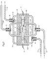
- Figures 1 and 2 show an implementation of the displacement principle. Man recognizes two line strings from the figures, namely one Water line 1.1 to 1.6 and a fuel line 2.1 to 2.6.
- Two-way solenoid valve B is switched such that the line sections 1.5 and 1.6 of the water pipe are in a conductive connection.
- Two-way solenoid valve D is switched such that the line sections 2.5, 2.6 of the fuel line are in a conductive connection. Due to the movement of the piston 4, partial flows of Fuel and water pressed into line sections 2.6 and 1.6. This Line sections are brought together (not shown here). The Total current is fed to an emulsifying device, not shown here.
- the water-fuel ratio remains constant. It is determined by the volumes of the piston-cylinder units involved. But you can also through the Changing the opening times of the valves in the water line Change ratio. This can be done continuously (e.g. electronically controlled by polling a power signal), so that any Mixing ratio from 0 to at most that determined by the volume Relationship can be established.
- Figure 2 shows that phase of the dosing device in which the piston 4 moves from its left position to its right position.
- the piston thus constantly executes a reciprocating movement, and indeed caused by the under pressure in the line section 2.1 inflowing fuel, and controlled by the solenoid valves, in the first Line through solenoid valve C.
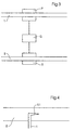
- FIG 3 an embodiment is shown in which the hydrodynamic principle is applied.
- a pump P switched
- the fuel line 2 a turbine T.
- Turbine T and pump P are in drive connection with each other.
- a Gearbox G switched, the translation of which is adjustable.
- This metering device works as follows: In the fuel line 2 is under Fuel under pressure is introduced so that the turbine is driven.
- the turbine drives the pump P via gearbox G. This sucks accordingly Water from a storage container, not shown, via line 1.
- FIG. 4 illustrates very schematically the application of Injector principle.
- a nozzle 1.1 is inserted into the fuel line 2, which is part of a water pipe 1.
- the method according to the invention already works when the pressure of the first partial flow in the first line is relatively low. Pressures of 0.5 bar are sufficient. 0.3 bar is also practical. In practice pressures between 0.5 and 1.0 bar will be used.
Landscapes
- Chemical & Material Sciences (AREA)
- Chemical Kinetics & Catalysis (AREA)
- Engineering & Computer Science (AREA)
- Combustion & Propulsion (AREA)
- Mechanical Engineering (AREA)
- General Engineering & Computer Science (AREA)
- Health & Medical Sciences (AREA)
- Public Health (AREA)
- Water Supply & Treatment (AREA)
- Fuel-Injection Apparatus (AREA)
- Jet Pumps And Other Pumps (AREA)
- Nozzles (AREA)
- Treatment Of Fiber Materials (AREA)
- Bakery Products And Manufacturing Methods Therefor (AREA)
- Output Control And Ontrol Of Special Type Engine (AREA)
Applications Claiming Priority (2)
| Application Number | Priority Date | Filing Date | Title |
|---|---|---|---|
| DE19819271A DE19819271A1 (de) | 1998-04-30 | 1998-04-30 | Dosiervorrichtung für eine Emulgieranlage |
| DE19819271 | 1998-04-30 |
Publications (2)
| Publication Number | Publication Date |
|---|---|
| EP0953760A1 true EP0953760A1 (fr) | 1999-11-03 |
| EP0953760B1 EP0953760B1 (fr) | 2001-08-01 |
Family
ID=7866251
Family Applications (1)
| Application Number | Title | Priority Date | Filing Date |
|---|---|---|---|
| EP99108120A Expired - Lifetime EP0953760B1 (fr) | 1998-04-30 | 1999-04-24 | Dispositif de dosage pour une installation de production d'une émulsion |
Country Status (3)
| Country | Link |
|---|---|
| EP (1) | EP0953760B1 (fr) |
| AT (1) | ATE203800T1 (fr) |
| DE (2) | DE19819271A1 (fr) |
Cited By (1)
| Publication number | Priority date | Publication date | Assignee | Title |
|---|---|---|---|---|
| DE102009005356A1 (de) | 2009-01-16 | 2010-07-22 | Voith Patent Gmbh | Verfahren und Vorrichtung zum Betrieb eines Dieselmotors mit einem Mischkraftstoff |
Citations (6)
| Publication number | Priority date | Publication date | Assignee | Title |
|---|---|---|---|---|
| US4063536A (en) * | 1975-11-07 | 1977-12-20 | Toyota Jidosha Kogyo Kabushiki Kaisha | Apparatus for feeding water into the air/fuel mixture passage of an internal combustion engine |
| US4461245A (en) * | 1982-04-13 | 1984-07-24 | Michael Vinokur | Fluid injection system for internal combustion engine |
| EP0263443A2 (fr) * | 1986-10-08 | 1988-04-13 | Zugol AG | Procédé et dispositif pour produire une émulsion eau-en-huile |
| EP0545334A2 (fr) * | 1991-12-03 | 1993-06-09 | Roland Steinmaier | Dispositif pour produire une émulsion gazole-eau |
| EP0674941A1 (fr) * | 1994-03-12 | 1995-10-04 | MTU Motoren- und Turbinen-Union Friedrichshafen GmbH | Dispositif pour la fabrication d'une émulsion huile-eau |
| EP0721063A2 (fr) * | 1991-11-12 | 1996-07-10 | SCHREYÖGG, Josef | Procédé et appareil d'alimentation en carburant émulsionné |
Family Cites Families (4)
| Publication number | Priority date | Publication date | Assignee | Title |
|---|---|---|---|---|
| DE2906300C2 (de) * | 1978-02-23 | 1984-05-24 | Becton, Dickinson and Co., 07652 Paramus, N.J. | Regelbare Dosiervorrichtung für Flüssigkeiten |
| DE3611728C1 (de) * | 1986-04-08 | 1987-04-16 | Meinz Hans Willi | Vorrichtung zum Dosieren und Mischen von fliessfaehigen Mehrkomponentensystemen |
| DE4235528C2 (de) * | 1992-10-21 | 1994-08-18 | Alfred Schmid Ag Plastikwerk | Vorrichtung zum Dosieren und Mischen von zwei unterschiedlichen, viskosen Massen, insbesondere Dentalmassen |
| DE4323160C1 (de) * | 1993-07-10 | 1995-01-19 | Hilger & Kern Gmbh | Mehrkomponenten-Dosiereinrichtung |
-
1998
- 1998-04-30 DE DE19819271A patent/DE19819271A1/de not_active Withdrawn
-
1999
- 1999-04-24 AT AT99108120T patent/ATE203800T1/de not_active IP Right Cessation
- 1999-04-24 DE DE59900174T patent/DE59900174D1/de not_active Expired - Lifetime
- 1999-04-24 EP EP99108120A patent/EP0953760B1/fr not_active Expired - Lifetime
Patent Citations (6)
| Publication number | Priority date | Publication date | Assignee | Title |
|---|---|---|---|---|
| US4063536A (en) * | 1975-11-07 | 1977-12-20 | Toyota Jidosha Kogyo Kabushiki Kaisha | Apparatus for feeding water into the air/fuel mixture passage of an internal combustion engine |
| US4461245A (en) * | 1982-04-13 | 1984-07-24 | Michael Vinokur | Fluid injection system for internal combustion engine |
| EP0263443A2 (fr) * | 1986-10-08 | 1988-04-13 | Zugol AG | Procédé et dispositif pour produire une émulsion eau-en-huile |
| EP0721063A2 (fr) * | 1991-11-12 | 1996-07-10 | SCHREYÖGG, Josef | Procédé et appareil d'alimentation en carburant émulsionné |
| EP0545334A2 (fr) * | 1991-12-03 | 1993-06-09 | Roland Steinmaier | Dispositif pour produire une émulsion gazole-eau |
| EP0674941A1 (fr) * | 1994-03-12 | 1995-10-04 | MTU Motoren- und Turbinen-Union Friedrichshafen GmbH | Dispositif pour la fabrication d'une émulsion huile-eau |
Cited By (1)
| Publication number | Priority date | Publication date | Assignee | Title |
|---|---|---|---|---|
| DE102009005356A1 (de) | 2009-01-16 | 2010-07-22 | Voith Patent Gmbh | Verfahren und Vorrichtung zum Betrieb eines Dieselmotors mit einem Mischkraftstoff |
Also Published As
| Publication number | Publication date |
|---|---|
| DE19819271A1 (de) | 1999-11-11 |
| EP0953760B1 (fr) | 2001-08-01 |
| ATE203800T1 (de) | 2001-08-15 |
| DE59900174D1 (de) | 2001-09-06 |
Similar Documents
| Publication | Publication Date | Title |
|---|---|---|
| EP1952006B1 (fr) | Dispositif pour produire une micro-emulsion d'eau et de gazole et pour injecter cette emulsion dans un moteur diesel | |
| DE2126736A1 (de) | Kraftstoffeinspntzanlage fur Brenn kraftmaschinen | |
| DE2921490A1 (de) | Kraftstoffeinspritzsteuersystem fuer verbrennungsmotoren | |
| DE3127831A1 (de) | "system und vorrichtung zum pumpen" | |
| DE2054487A1 (de) | Hydrostatische Druckantriebsma schine | |
| DE10010945B4 (de) | Pumpe zur Versorgung eines Kraftstoffeinspritzsystems und einer hydraulischen Ventilsteuerung für Brennkraftmaschinen | |
| EP0915252A2 (fr) | Système d'injection par alimentation commune des injecteurs | |
| EP0953760B1 (fr) | Dispositif de dosage pour une installation de production d'une émulsion | |
| DE10154133C1 (de) | Kraftstoffsystem | |
| EP0400693A2 (fr) | Pompe à haute pression | |
| EP1361357A2 (fr) | Pompe à carburant notamment pour un moteur à combustion interne et à injection directe | |
| EP0007109A1 (fr) | Appareil pour le dosage d'une solution d'agents chimiques dans un courant de liquide | |
| DE4425339C2 (de) | Einspritzsystem | |
| DE4205144A1 (de) | Vorrichtung zum pneumatischen ausbringen von hydromechanisch im dichtstrom gefoerdertem beton | |
| DE2422882A1 (de) | Einspritzanlage fuer brennkraftmaschinen | |
| DE3509770A1 (de) | Kraftstoffeinspritzeinheit | |
| DE102018202825B3 (de) | Vorrichtung und Verfahren zum Fördern von Kraftstoff und Additiv | |
| DE1244469B (de) | Kraftstoffeinspritzanlage fuer Brennkraftmaschinen, insbesondere Dieselmotoren, mit einer den Foerderbeginn der Einspritzpumpe aendernden Verstelleinrichtung | |
| DE2721628A1 (de) | Kraftstoffeinspritzanlage fuer verbrennungskraftmaschinen | |
| WO1995006815A1 (fr) | Procede et dispositif pour nettoyer un filtre a suie dans le systeme d'echappement d'un moteur a combustion interne a carburant diesel | |
| DE10305783A1 (de) | Kolbenmembranpumpe mit ölseitiger Bedarfssteuerung | |
| EP1496243B1 (fr) | Moteur à combustion interne | |
| CH616235A5 (en) | Device for testing fuel injection valves. | |
| DE1576189A1 (de) | Vorrichtung zur Einspritzung von fluessigem Brennstoff fuer Freiflugkolbenmotoren | |
| DE2626971A1 (de) | Kolbenpumpe zur verwendung mit einer druckoel fuehrenden hydraulikanlage |
Legal Events
| Date | Code | Title | Description |
|---|---|---|---|
| PUAI | Public reference made under article 153(3) epc to a published international application that has entered the european phase |
Free format text: ORIGINAL CODE: 0009012 |
|
| 17P | Request for examination filed |
Effective date: 19990813 |
|
| AK | Designated contracting states |
Kind code of ref document: A1 Designated state(s): AT DE FR IT |
|
| AX | Request for extension of the european patent |
Free format text: AL;LT;LV;MK;RO;SI |
|
| 17Q | First examination report despatched |
Effective date: 20000518 |
|
| AKX | Designation fees paid |
Free format text: AT DE FR IT |
|
| GRAG | Despatch of communication of intention to grant |
Free format text: ORIGINAL CODE: EPIDOS AGRA |
|
| GRAG | Despatch of communication of intention to grant |
Free format text: ORIGINAL CODE: EPIDOS AGRA |
|
| GRAH | Despatch of communication of intention to grant a patent |
Free format text: ORIGINAL CODE: EPIDOS IGRA |
|
| GRAH | Despatch of communication of intention to grant a patent |
Free format text: ORIGINAL CODE: EPIDOS IGRA |
|
| GRAA | (expected) grant |
Free format text: ORIGINAL CODE: 0009210 |
|
| AK | Designated contracting states |
Kind code of ref document: B1 Designated state(s): AT DE FR IT |
|
| REF | Corresponds to: |
Ref document number: 203800 Country of ref document: AT Date of ref document: 20010815 Kind code of ref document: T |
|
| REF | Corresponds to: |
Ref document number: 59900174 Country of ref document: DE Date of ref document: 20010906 |
|
| EN | Fr: translation not filed | ||
| EN | Fr: translation not filed |
Free format text: BO 01/52 PAGES: 283, IL Y A LIEU DE SUPPRIMER: LA MENTION DE LA NON REMISE. LA REMISE EST PUBLIEE DANS LE PRESENT BOPI. |
|
| ET | Fr: translation filed | ||
| PLBE | No opposition filed within time limit |
Free format text: ORIGINAL CODE: 0009261 |
|
| STAA | Information on the status of an ep patent application or granted ep patent |
Free format text: STATUS: NO OPPOSITION FILED WITHIN TIME LIMIT |
|
| 26N | No opposition filed | ||
| PGFP | Annual fee paid to national office [announced via postgrant information from national office to epo] |
Ref country code: FR Payment date: 20100428 Year of fee payment: 12 |
|
| PGFP | Annual fee paid to national office [announced via postgrant information from national office to epo] |
Ref country code: IT Payment date: 20100419 Year of fee payment: 12 Ref country code: DE Payment date: 20100526 Year of fee payment: 12 Ref country code: AT Payment date: 20100421 Year of fee payment: 12 |
|
| REG | Reference to a national code |
Ref country code: DE Ref legal event code: R119 Ref document number: 59900174 Country of ref document: DE |
|
| REG | Reference to a national code |
Ref country code: DE Ref legal event code: R119 Ref document number: 59900174 Country of ref document: DE |
|
| REG | Reference to a national code |
Ref country code: AT Ref legal event code: MM01 Ref document number: 203800 Country of ref document: AT Kind code of ref document: T Effective date: 20110424 |
|
| REG | Reference to a national code |
Ref country code: FR Ref legal event code: ST Effective date: 20111230 |
|
| PG25 | Lapsed in a contracting state [announced via postgrant information from national office to epo] |
Ref country code: FR Free format text: LAPSE BECAUSE OF NON-PAYMENT OF DUE FEES Effective date: 20110502 |
|
| PG25 | Lapsed in a contracting state [announced via postgrant information from national office to epo] |
Ref country code: IT Free format text: LAPSE BECAUSE OF NON-PAYMENT OF DUE FEES Effective date: 20110424 Ref country code: AT Free format text: LAPSE BECAUSE OF NON-PAYMENT OF DUE FEES Effective date: 20110424 |
|
| PG25 | Lapsed in a contracting state [announced via postgrant information from national office to epo] |
Ref country code: DE Free format text: LAPSE BECAUSE OF NON-PAYMENT OF DUE FEES Effective date: 20111031 |