EP0545657A1 - Metallische Hülsen zum luftdichten Abschliessen von elektrischen Lampen - Google Patents
Metallische Hülsen zum luftdichten Abschliessen von elektrischen Lampen Download PDFInfo
- Publication number
- EP0545657A1 EP0545657A1 EP92310921A EP92310921A EP0545657A1 EP 0545657 A1 EP0545657 A1 EP 0545657A1 EP 92310921 A EP92310921 A EP 92310921A EP 92310921 A EP92310921 A EP 92310921A EP 0545657 A1 EP0545657 A1 EP 0545657A1
- Authority
- EP
- European Patent Office
- Prior art keywords
- ferrule
- lamp
- nickel
- glass
- article
- Prior art date
- Legal status (The legal status is an assumption and is not a legal conclusion. Google has not performed a legal analysis and makes no representation as to the accuracy of the status listed.)
- Withdrawn
Links
Images

Classifications
-
- H—ELECTRICITY
- H01—ELECTRIC ELEMENTS
- H01R—ELECTRICALLY-CONDUCTIVE CONNECTIONS; STRUCTURAL ASSOCIATIONS OF A PLURALITY OF MUTUALLY-INSULATED ELECTRICAL CONNECTING ELEMENTS; COUPLING DEVICES; CURRENT COLLECTORS
- H01R4/00—Electrically-conductive connections between two or more conductive members in direct contact, i.e. touching one another; Means for effecting or maintaining such contact; Electrically-conductive connections having two or more spaced connecting locations for conductors and using contact members penetrating insulation
- H01R4/58—Electrically-conductive connections between two or more conductive members in direct contact, i.e. touching one another; Means for effecting or maintaining such contact; Electrically-conductive connections having two or more spaced connecting locations for conductors and using contact members penetrating insulation characterised by the form or material of the contacting members
- H01R4/62—Connections between conductors of different materials; Connections between or with aluminium or steel-core aluminium conductors
-
- C—CHEMISTRY; METALLURGY
- C03—GLASS; MINERAL OR SLAG WOOL
- C03C—CHEMICAL COMPOSITION OF GLASSES, GLAZES OR VITREOUS ENAMELS; SURFACE TREATMENT OF GLASS; SURFACE TREATMENT OF FIBRES OR FILAMENTS MADE FROM GLASS, MINERALS OR SLAGS; JOINING GLASS TO GLASS OR OTHER MATERIALS
- C03C27/00—Joining pieces of glass to pieces of other inorganic material; Joining glass to glass other than by fusing
- C03C27/04—Joining glass to metal by means of an interlayer
- C03C27/042—Joining glass to metal by means of an interlayer consisting of a combination of materials selected from glass, glass-ceramic or ceramic material with metals, metal oxides or metal salts
- C03C27/046—Joining glass to metal by means of an interlayer consisting of a combination of materials selected from glass, glass-ceramic or ceramic material with metals, metal oxides or metal salts of metals, metal oxides or metal salts only
-
- H—ELECTRICITY
- H01—ELECTRIC ELEMENTS
- H01J—ELECTRIC DISCHARGE TUBES OR DISCHARGE LAMPS
- H01J5/00—Details relating to vessels or to leading-in conductors common to two or more basic types of discharge tubes or lamps
- H01J5/50—Means forming part of the tube or lamps for the purpose of providing electrical connection to it
-
- H—ELECTRICITY
- H01—ELECTRIC ELEMENTS
- H01J—ELECTRIC DISCHARGE TUBES OR DISCHARGE LAMPS
- H01J9/00—Apparatus or processes specially adapted for the manufacture, installation, removal, maintenance of electric discharge tubes, discharge lamps, or parts thereof; Recovery of material from discharge tubes or lamps
- H01J9/24—Manufacture or joining of vessels, leading-in conductors or bases
-
- H—ELECTRICITY
- H01—ELECTRIC ELEMENTS
- H01R—ELECTRICALLY-CONDUCTIVE CONNECTIONS; STRUCTURAL ASSOCIATIONS OF A PLURALITY OF MUTUALLY-INSULATED ELECTRICAL CONNECTING ELEMENTS; COUPLING DEVICES; CURRENT COLLECTORS
- H01R13/00—Details of coupling devices of the kinds covered by groups H01R12/70 or H01R24/00 - H01R33/00
- H01R13/02—Contact members
- H01R13/03—Contact members characterised by the material, e.g. plating, or coating materials
Definitions
- This invention relates to metal ferrules used to form a hermetic seal with glass in the fabrication of electric lamps. More particularly this invention relates to a nickel-plated, high nickel content iron alloy ferrule which is used in the fabrication of electric lamps and which must form a hermetic seal with a glass lamp envelope and possess solderability, and lamps employing same.
- ferrules in a variety of lamps to provide a means for supporting the light source within the lamp and for providing an electrically conductive means for supplying electricity to energize the lamp source from outside the lamp.
- These ferrules also function to hermetically seal the lamp by means of a hermetic seal to the glass envelope.
- the ferrules are generally cup- or thimble-shaped, open at one end and closed at the other, with the open end of the ferrule tapering to a feather or knife edge for forming a hermetic seal with the soft, hot glass into which the ferrule is pressed.
- ferrule In order for the ferrule to be able to make a hermetic seal with glass the ferrule must have a thermal coefficient of expansion similar enough to that of the glass. At the present time these ferrules are fabricated from a high nickel content iron alloy. A typical ferrule is made of an alloy consisting essentially of 42% nickel with the remainder iron. This alloy has thermal expansion and contraction characteristics which enable it to form a hermetic seal with glass.
- the present invention relates to a nickel-plated, high nickel content, iron alloy lamp ferrule which will form a hermetic seal with glass and whose exterior surface forms strong bonds with solder after being heated above its surface oxidation temperature of 250-300°C and reduced.
- the invention relates to electric lamps containing such ferrules.
- the ferrules of the invention on lamps has resulted in an average solder torque strength of the lamp's exterior electrical connecting means to the ferrule 50% higher than with similar ferrules that are not nickel plated and that this strength remains at this high level even after exposure to extreme humidity and salt spray.
- the nickel-plated, high nickel content iron alloy of the invention can be used in other shapes and products for forming a seal with or bonding to glass, such as in the semiconductor and glass products industries.
- the invention relates to a solderable material for bonding to glass and also for forming a hermetic seal with glass which comprises a nickel-plated, high nickel content iron alloy.
- high nickel content iron alloy is meant an iron alloy having a nickel content broadly ranging from 35-52 wt. % with the remainder being iron.
- Employing lamp ferrules of this invention has reduced soldering defects by 50%.
- Figure 1 schematically illustrates a ferrule made of a nickel-plated, high nickel content iron alloy according to the invention.
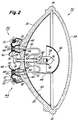
- Figure 2 schematically illustrates one embodiment of a lamp employing ferrules according to the invention.
- FIG. 1 there is schematically illustrated a side view and a top view of a typical lamp ferrule employed in lamp construction useful in accordance with the present invention.
- ferrule 10 is shown as being generally shaped like a cylindrical cup or thimble closed at its smaller end 12 (nib end) and open at its widest end 22 (skirt end) having a nominal overall height of about 1/2 inch and a nominal width at its open end 22 (which is its largest end) of about 7/16 inch.
- the ferrule is fabricated by pressing or drawing a disk of high nickel content iron alloy, nominally about 7-1/2 mils thick, through a series of dies. As it can be seen from Figures 1(a) and 1(b), the ferrule has three steps of gradually increasing diameter with the cylindrical wall of the open end portion 16 being tapered to a feathered edge 18 having a thickness of about 4 mils approximately 10 mils up from the bottom 22. This thin feathered edge is required in order to achieve a hermetic seal with the glass into which it is pressed.
- the ferrules of the invention are nickel-plated, high nickel content iron alloy and are made from nickel-plated, high nickel content iron alloy sheet or strip metal. The alloy comprises nickel and iron with the nickel content broadly ranging between 35-52 wt.
- FIG. 2 schematically illustrates one embodiment of a lamp 30 employing ferrules 10 of the invention, wherein the lamp construction is the type used in display lighting in department stores.
- lamp 30 consists of a preformed pressed glass reflector section 32 and a preformed glass cover section or lens 34 fusion-sealed together at their peripheries, as indicated at 36.
- Lens or cover section 34 may be made of clear glass, or it may be stippled or otherwise rendered light-diffusing. Further, if desired, lens 34 may contain an optical interference coating for changing the color of the light emitted by the lamp or it may contain an ultraviolet or infrared absorbing or reflecting coating if the light source 54 contained within emits undesirable UV radiation.
- the inner reflecting surface 38 of reflector section 32 is provided with a light-reflecting coating 40 and is substantially parabolic in shape to project the light emitted by the light source in a forward direction.
- Light-reflecting coating 40 may be aluminum, other metal, an optical interference coating, etc., as is known to those skilled in the art.
- the rear outer portion of reflector section 32 terminates in a pair of raised glass portions or bosses 42 onto each of which is mounted a base structure 44.
- Each of base structures 44 is identical and each comprises an electrical terminal contact 46 in the form of a metal strap or lug, having a downwardly protruding cup-shaped cavity 48, the open cylindrical wall 50 of which fits over nib end 12 of ferrule 10.
- Electrical contact 46 is secured to the outer wall surface 12 of the nib portion of ferrule 10 by soldering.
- Screw terminal 52 is provided on contact 46 for connecting current supply wires thereto.
- Ferrules 10 are pressed into boss sections 42 of reflector section 32 while the glass is sufficiently hot to be deformed by and to wet and bond to the feathered edge bottom end 18 of the ferrule as will be described in greater detail below.
- Electrically conductive support rods 52 pass through holes 54 in glass reflector section 32 and are brazed into the interior cavity 22 of nib section 12 of ferrules 10.
- Support rods 52 support a light source 54 which can be a filament, a double-ended or a single-ended lamp, either incandescent or arc discharge (c.f., U.S.
- the light source is illustrated as a single-ended incandescent (i.e., a tungsten-halogen lamp) lamp having a high temperature glass or fused quartz vitreous envelope in which filament 56 is supported by inleads 58 which pass through molybdenum foil seals 60 and thence to outer leads 62 which are welded onto supports 52.
- incandescent i.e., a tungsten-halogen lamp
- reflector support rod 64 is also welded to light source support rod 52 and attached at its other end to an opaque, black, metal bowl-shaped light shield member 66 which is positioned over light source 54 to insure that all of the light projected forward of lamp 30 is light that has been reflected off light-reflecting surface 38.
- an inert gas such as argon is introduced into the lamp via exhaust tube 14 which is then press sealed at 16.
- each of the two ferrules 10 are placed onto respective bossed area 42 of glass reflector section 32 while the glass is hot (about 700°C).
- the ferrules are then heated to a cherry red color (about 1000°C) and pushed into the respective bosses 42 to form a hermetic seal at the thin feathered edge portion 18 of the ferrule, after which the assembly is permitted to cool down to room temperature.
- light source support wires or rods 52 are inserted into the interior cavity 22 of nib portion 12 of respective ferrules 10 and are brazed into said interior portion by means of a brazing compound.
- the nib portion 12 of the ferrules 10 is heated to a cherry red color again (about 1000°C). These two heating steps result in an oxidized outer ferrule surface, particularly at the nib portion 12 of ferrule 10 to which the electrical contact strap 56 must subsequently be attached to by soldering.
- the high nickel content iron alloy surface starts to oxidize at a temperature of about 250°C and during the lamp-making process this temperature is greatly exceeded during the two operations just described. As a consequence, the outside surface of the ferrule, particularly at the nib portion 12, becomes oxidized. Consequently, the outer ferrule surface must be reduced back to metal in order to be able to solder the electrical base straps onto the ferrule in a subsequent soldering operation. The oxidized surface is reduced in hydrogen during the next step in the lamp manufacturing process.
- the reflector and ferrule assembly goes to another station where the hot ferrule is cooled under flowing hydrogen to reduce the surface oxide formed by the previous heating steps back to metal.
- Yet another heating cycle can occur if the lens is glass which is fusion-welded (as opposed to cemented) to the glass reflector which can heat the ferrule back up to about the oxidation temperature.
- This new oxidation is generally, but not always, removed by the solder flux when the metal electrical contact strap 46 is soldered to the nib portion of the ferrule 10.
- an essentially non-corrosive solder flux such as an activated organic resin flux with either a lead-containing solder, such as a 60/40 or 95/5 lead/tin solder or a lead-free solder such as 5/95 antimony/tin, 100% tin or Aqua Clean solder (96 Sn/3.5Bi/0.2Cu-0.2Aq) available from Federated Fry Metals.
- a lead-containing solder such as a 60/40 or 95/5 lead/tin solder or a lead-free solder such as 5/95 antimony/tin, 100% tin or Aqua Clean solder (96 Sn/3.5Bi/0.2Cu-0.2Aq) available from Federated Fry Metals.
- a lead-containing solder such as a 60/40 or 95/5 lead/tin solder or a lead-free solder such as 5/95 antimony/tin, 100% tin or Aqua Clean solder (96 Sn/3.5Bi/0.2Cu-0.2Aq) available from Federated Fry Metals.
- the ferrules were made with the nickel plating primarily on the outside of the ferrule which is where the nickel is needed in order to obtain a good solder bond.
- Some nickel plate was present on the other side (i.e., ⁇ 10 microinches with a nominal 50 microinch plating), but one avoids the presence of heavy, porous nickel plate on the feathered edge which must make the hermetic seal to the glass.
- Employing this new ferrule has resulted in reducing the amount of solder used with no failures due to weak solder bonds when making lamps according to the above-illustrated process using a non-corrosive solder flux, even with lead-free solders.
- the above has been directed toward achieving a hermetic seal or bonding between a nickel-plated, high nickel content iron alloy lamp ferrule and a lamp glass envelope, it will be appreciated by those skilled in the art that the invention will lend itself to other uses.
- the invention is directed toward an article of manufacture useful for forming a hermetic seal with glass and which possesses good solderability to solder using a non-corrosive solder flux with both lead-containing and lead-free solders after being heated above the oxidation temperature of about 250-300°C in an oxidizing atmosphere, such as air at least once.
Landscapes
- Engineering & Computer Science (AREA)
- Chemical & Material Sciences (AREA)
- Ceramic Engineering (AREA)
- Manufacturing & Machinery (AREA)
- Life Sciences & Earth Sciences (AREA)
- Chemical Kinetics & Catalysis (AREA)
- General Chemical & Material Sciences (AREA)
- Geochemistry & Mineralogy (AREA)
- Materials Engineering (AREA)
- Organic Chemistry (AREA)
- Common Detailed Techniques For Electron Tubes Or Discharge Tubes (AREA)
Applications Claiming Priority (2)
| Application Number | Priority Date | Filing Date | Title |
|---|---|---|---|
| US07/802,024 US5287037A (en) | 1991-12-03 | 1991-12-03 | Metal ferrules for hermetically sealing electric lamps |
| US802024 | 1991-12-03 |
Publications (1)
| Publication Number | Publication Date |
|---|---|
| EP0545657A1 true EP0545657A1 (de) | 1993-06-09 |
Family
ID=25182648
Family Applications (1)
| Application Number | Title | Priority Date | Filing Date |
|---|---|---|---|
| EP92310921A Withdrawn EP0545657A1 (de) | 1991-12-03 | 1992-11-30 | Metallische Hülsen zum luftdichten Abschliessen von elektrischen Lampen |
Country Status (4)
| Country | Link |
|---|---|
| US (1) | US5287037A (de) |
| EP (1) | EP0545657A1 (de) |
| JP (1) | JPH05242873A (de) |
| CA (1) | CA2082707A1 (de) |
Families Citing this family (5)
| Publication number | Priority date | Publication date | Assignee | Title |
|---|---|---|---|---|
| EP0392509B1 (de) * | 1989-04-13 | 1995-01-04 | Shin-Etsu Chemical Co., Ltd. | 3-(2-Oxo-1-pyrrolidinyl)-propylsilane und Verfahren zur Herstellung der Silanverbindungen |
| US6133676A (en) * | 1997-09-10 | 2000-10-17 | Chen; Chun Tsun | Double-enveloped halogen bulb provided with protuberances in the outer surface of the envelope |
| EP1588400A2 (de) * | 2003-01-15 | 2005-10-26 | Philips Intellectual Property & Standards GmbH | Lampe und beleuchtungseinheit mit interferenzbeschichtung und blockierender bauteil zur verbesserten uniformität der farbtemperatur |
| CN113074509B (zh) * | 2020-01-06 | 2024-07-12 | 青岛海尔电冰箱有限公司 | 真空绝热体及冰箱 |
| CN113936992B (zh) * | 2021-09-30 | 2023-12-19 | 镇江震东电光源有限公司 | 一种用于灯头连接点的酸洗注锡装置 |
Citations (16)
| Publication number | Priority date | Publication date | Assignee | Title |
|---|---|---|---|---|
| US3868529A (en) * | 1973-05-24 | 1975-02-25 | Gen Electric | Halogen lamp containing nickel-plated parts |
| US4103416A (en) * | 1975-10-21 | 1978-08-01 | New Nippon Electric Co., Ltd. | Method of manufacturing an hermatically sealed electrical terminal |
| SU625878A1 (ru) * | 1977-05-27 | 1978-08-21 | Предприятие П/Я Р-6793 | Флюс дл низкотемпературной пайки |
| US4270986A (en) * | 1979-07-12 | 1981-06-02 | Sifco Industries, Inc. | Method for soldering aluminum |
| JPS60130027A (ja) * | 1983-12-15 | 1985-07-11 | Matsushita Electric Ind Co Ltd | 画像表示装置の製造方法 |
| US4695428A (en) * | 1986-08-21 | 1987-09-22 | J. W. Harris Company | Solder composition |
| GB2190923A (en) * | 1986-05-13 | 1987-12-02 | Nisshin Steel Co Ltd | Metal sheet for sealing to soft glass |
| EP0251611A2 (de) * | 1986-07-03 | 1988-01-07 | Engelhard Corporation | Gering giftiges korrosionsbeständiges Lot |
| FR2608954A1 (fr) * | 1986-12-29 | 1988-07-01 | Videocolor | Procede de desoxydation de conducteurs d'embases notamment pour tubes a vide et dispositif pour la mise en oeuvre de ce procede |
| JPS63310933A (ja) * | 1987-06-12 | 1988-12-19 | Furukawa Electric Co Ltd:The | 電子機器用パッケ−ジのリ−ド材 |
| EP0336575A1 (de) * | 1988-03-31 | 1989-10-11 | COOKSON GROUP plc | Legierungszusammensetzungen mit niedriger Toxizität zum Verbinden und Abdichten |
| JPH01293504A (ja) * | 1988-05-20 | 1989-11-27 | Matsushita Electric Ind Co Ltd | ガラス封入形サーミスタの製造法 |
| US4908546A (en) * | 1988-06-27 | 1990-03-13 | Gte Products Corporation | Lead-in wire for compact fluorescent lamps |
| JPH02144864A (ja) * | 1988-11-26 | 1990-06-04 | Nec Kansai Ltd | 気密端子の製造方法 |
| EP0429256A2 (de) * | 1989-11-17 | 1991-05-29 | General Electric Company | Verbesserte Aufbauzuordnung für Doppelendlampe |
| EP0499452A1 (de) * | 1991-02-13 | 1992-08-19 | Lancashire Fittings Limited | Bleifreies Weichlot zum Löten von rostfreien Stahl |
Family Cites Families (5)
| Publication number | Priority date | Publication date | Assignee | Title |
|---|---|---|---|---|
| US2148314A (en) * | 1937-05-19 | 1939-02-21 | Gen Electric | Electric lamp |
| US2597681A (en) * | 1950-07-01 | 1952-05-20 | Gen Electric | Electric incandescent lamp |
| US2605436A (en) * | 1950-07-01 | 1952-07-29 | Gen Electric | Electric incandescent lamp |
| JPS5115650B2 (de) * | 1971-12-28 | 1976-05-18 | ||
| JPS50152579A (de) * | 1974-05-27 | 1975-12-08 |
-
1991
- 1991-12-03 US US07/802,024 patent/US5287037A/en not_active Expired - Fee Related
-
1992
- 1992-11-12 CA CA002082707A patent/CA2082707A1/en not_active Abandoned
- 1992-11-30 EP EP92310921A patent/EP0545657A1/de not_active Withdrawn
- 1992-12-02 JP JP4322848A patent/JPH05242873A/ja active Pending
Patent Citations (16)
| Publication number | Priority date | Publication date | Assignee | Title |
|---|---|---|---|---|
| US3868529A (en) * | 1973-05-24 | 1975-02-25 | Gen Electric | Halogen lamp containing nickel-plated parts |
| US4103416A (en) * | 1975-10-21 | 1978-08-01 | New Nippon Electric Co., Ltd. | Method of manufacturing an hermatically sealed electrical terminal |
| SU625878A1 (ru) * | 1977-05-27 | 1978-08-21 | Предприятие П/Я Р-6793 | Флюс дл низкотемпературной пайки |
| US4270986A (en) * | 1979-07-12 | 1981-06-02 | Sifco Industries, Inc. | Method for soldering aluminum |
| JPS60130027A (ja) * | 1983-12-15 | 1985-07-11 | Matsushita Electric Ind Co Ltd | 画像表示装置の製造方法 |
| GB2190923A (en) * | 1986-05-13 | 1987-12-02 | Nisshin Steel Co Ltd | Metal sheet for sealing to soft glass |
| EP0251611A2 (de) * | 1986-07-03 | 1988-01-07 | Engelhard Corporation | Gering giftiges korrosionsbeständiges Lot |
| US4695428A (en) * | 1986-08-21 | 1987-09-22 | J. W. Harris Company | Solder composition |
| FR2608954A1 (fr) * | 1986-12-29 | 1988-07-01 | Videocolor | Procede de desoxydation de conducteurs d'embases notamment pour tubes a vide et dispositif pour la mise en oeuvre de ce procede |
| JPS63310933A (ja) * | 1987-06-12 | 1988-12-19 | Furukawa Electric Co Ltd:The | 電子機器用パッケ−ジのリ−ド材 |
| EP0336575A1 (de) * | 1988-03-31 | 1989-10-11 | COOKSON GROUP plc | Legierungszusammensetzungen mit niedriger Toxizität zum Verbinden und Abdichten |
| JPH01293504A (ja) * | 1988-05-20 | 1989-11-27 | Matsushita Electric Ind Co Ltd | ガラス封入形サーミスタの製造法 |
| US4908546A (en) * | 1988-06-27 | 1990-03-13 | Gte Products Corporation | Lead-in wire for compact fluorescent lamps |
| JPH02144864A (ja) * | 1988-11-26 | 1990-06-04 | Nec Kansai Ltd | 気密端子の製造方法 |
| EP0429256A2 (de) * | 1989-11-17 | 1991-05-29 | General Electric Company | Verbesserte Aufbauzuordnung für Doppelendlampe |
| EP0499452A1 (de) * | 1991-02-13 | 1992-08-19 | Lancashire Fittings Limited | Bleifreies Weichlot zum Löten von rostfreien Stahl |
Non-Patent Citations (5)
| Title |
|---|
| DATABASE WPI Section Ch, Week 2979, 1979 Derwent Publications Ltd., London, GB; Class E, AN 79-54111B & SU-A-625 878 (LISITSKII) 21 August 1978 * |
| PATENT ABSTRACTS OF JAPAN vol. 13, no. 156 (C-585)14 April 1989 & JP-A-63 310 933 ( FURUKAWA ELECTRIC CO LTD ) 19 December 1988 * |
| PATENT ABSTRACTS OF JAPAN vol. 14, no. 391 (E-968)23 August 1990 & JP-A-02 144 864 ( NEC KANSAI LTD ) 4 June 1990 * |
| PATENT ABSTRACTS OF JAPAN vol. 14, no. 82 (E-889)15 February 1990 & JP-A-01 293 504 ( MATSUSHITA ELECTRIC IND CO LTD ) 27 November 1989 * |
| PATENT ABSTRACTS OF JAPAN vol. 9, no. 288 (E-358)15 November 1985 & JP-A-60 130 027 ( MATSUSHITA DENKI SANGYO KK ) 11 July 1985 * |
Also Published As
| Publication number | Publication date |
|---|---|
| JPH05242873A (ja) | 1993-09-21 |
| CA2082707A1 (en) | 1993-06-04 |
| US5287037A (en) | 1994-02-15 |
Similar Documents
| Publication | Publication Date | Title |
|---|---|---|
| US4015165A (en) | Electric lamp with molybdenum contact pins surrounded by non-corrosive metal sleeves | |
| US5287037A (en) | Metal ferrules for hermetically sealing electric lamps | |
| US7955153B2 (en) | Compound body and a process for the production of a mechanical connection | |
| JP2992765B2 (ja) | 電 灯 | |
| US2490776A (en) | Manufacture of sealed lighting unit | |
| EP1515361B1 (de) | Niederspannungsentladungslampe und verfahren zu ihrer herstellung | |
| JP2002528880A (ja) | 白熱ランプ | |
| US3885186A (en) | Lamp cap connections using superplastic alloy | |
| US3785020A (en) | Method of basing electrical devices | |
| CA1181122A (en) | Electric lamp having a lamp cap which is connected without cement | |
| US4827189A (en) | Solder connection for an electrode of the gas discharge lamp and the method for manufacture | |
| US5382874A (en) | Self-aligning light directing surface mountable miniature incandescent lamp | |
| EP0692813A2 (de) | Aus Kupfer und Stahl gefertigtes Leitungsdraht und dessen Anwendung in elektrischen Glühwendellampen | |
| JPH11502663A (ja) | 電球及び電球の製造方法 | |
| US3818558A (en) | Method of making lamp cap connections using superplastic alloy | |
| KR100940372B1 (ko) | 외부 전극형 방전 램프 및 그 제조 방법, 및 액정디스플레이 장치 | |
| JPH08186061A (ja) | 固体電解コンデンサの製造方法 | |
| JP3555051B2 (ja) | ガラス封着用金属線および管球ならびに電気部品 | |
| JP2004273358A (ja) | ガラス封着用金属線および管球ならびに電気部品 | |
| JPS6330111Y2 (de) | ||
| JP2006004800A (ja) | 口金および管形ランプ | |
| JPS585325Y2 (ja) | 管球 | |
| JPS6362360A (ja) | ガラス封止型ダイオ−ド | |
| JPS6369139A (ja) | 接点付白熱電球の製造方法 | |
| JPS604548B2 (ja) | 電球用マウント |
Legal Events
| Date | Code | Title | Description |
|---|---|---|---|
| PUAI | Public reference made under article 153(3) epc to a published international application that has entered the european phase |
Free format text: ORIGINAL CODE: 0009012 |
|
| AK | Designated contracting states |
Kind code of ref document: A1 Designated state(s): BE DE ES FR GB IT NL |
|
| 18D | Application deemed to be withdrawn |
Effective date: 19931210 |