EP0545767A1 - Kernreaktor mit einer Vorrichtung zum Auffangen und Kühlen von geschmolzenen Spaltzonenmassen als Folge eines Unfalles - Google Patents
Kernreaktor mit einer Vorrichtung zum Auffangen und Kühlen von geschmolzenen Spaltzonenmassen als Folge eines Unfalles Download PDFInfo
- Publication number
- EP0545767A1 EP0545767A1 EP92403140A EP92403140A EP0545767A1 EP 0545767 A1 EP0545767 A1 EP 0545767A1 EP 92403140 A EP92403140 A EP 92403140A EP 92403140 A EP92403140 A EP 92403140A EP 0545767 A1 EP0545767 A1 EP 0545767A1
- Authority
- EP
- European Patent Office
- Prior art keywords
- nuclear reactor
- profiled elements
- well
- reactor according
- tank
- Prior art date
- Legal status (The legal status is an assumption and is not a legal conclusion. Google has not performed a legal analysis and makes no representation as to the accuracy of the status listed.)
- Granted
Links
- 238000001816 cooling Methods 0.000 title claims abstract description 19
- 229910052751 metal Inorganic materials 0.000 claims abstract description 32
- 239000002184 metal Substances 0.000 claims abstract description 29
- XLYOFNOQVPJJNP-UHFFFAOYSA-N water Substances O XLYOFNOQVPJJNP-UHFFFAOYSA-N 0.000 claims abstract description 22
- 230000000284 resting effect Effects 0.000 claims abstract description 3
- 239000000498 cooling water Substances 0.000 claims description 3
- 230000003014 reinforcing effect Effects 0.000 claims description 2
- 238000004873 anchoring Methods 0.000 claims 1
- 230000002787 reinforcement Effects 0.000 claims 1
- 230000008018 melting Effects 0.000 description 5
- 238000002844 melting Methods 0.000 description 5
- 238000011084 recovery Methods 0.000 description 4
- 239000000446 fuel Substances 0.000 description 3
- 239000000463 material Substances 0.000 description 3
- 230000006378 damage Effects 0.000 description 2
- 230000003247 decreasing effect Effects 0.000 description 2
- 230000014759 maintenance of location Effects 0.000 description 2
- 239000000155 melt Substances 0.000 description 2
- 239000011819 refractory material Substances 0.000 description 2
- 230000000717 retained effect Effects 0.000 description 2
- 239000002689 soil Substances 0.000 description 2
- 230000000712 assembly Effects 0.000 description 1
- 238000000429 assembly Methods 0.000 description 1
- 238000009835 boiling Methods 0.000 description 1
- 239000004020 conductor Substances 0.000 description 1
- 230000007547 defect Effects 0.000 description 1
- 239000006185 dispersion Substances 0.000 description 1
- 230000000694 effects Effects 0.000 description 1
- 239000012530 fluid Substances 0.000 description 1
- 239000003673 groundwater Substances 0.000 description 1
- 238000002347 injection Methods 0.000 description 1
- 239000007924 injection Substances 0.000 description 1
- 239000007788 liquid Substances 0.000 description 1
- 238000007712 rapid solidification Methods 0.000 description 1
- 238000009877 rendering Methods 0.000 description 1
- 238000007711 solidification Methods 0.000 description 1
- 230000008023 solidification Effects 0.000 description 1
- 230000001052 transient effect Effects 0.000 description 1
- 238000003466 welding Methods 0.000 description 1
Images


Classifications
-
- G—PHYSICS
- G21—NUCLEAR PHYSICS; NUCLEAR ENGINEERING
- G21C—NUCLEAR REACTORS
- G21C9/00—Emergency protection arrangements structurally associated with the reactor, e.g. safety valves provided with pressure equalisation devices
- G21C9/016—Core catchers
-
- Y—GENERAL TAGGING OF NEW TECHNOLOGICAL DEVELOPMENTS; GENERAL TAGGING OF CROSS-SECTIONAL TECHNOLOGIES SPANNING OVER SEVERAL SECTIONS OF THE IPC; TECHNICAL SUBJECTS COVERED BY FORMER USPC CROSS-REFERENCE ART COLLECTIONS [XRACs] AND DIGESTS
- Y02—TECHNOLOGIES OR APPLICATIONS FOR MITIGATION OR ADAPTATION AGAINST CLIMATE CHANGE
- Y02E—REDUCTION OF GREENHOUSE GAS [GHG] EMISSIONS, RELATED TO ENERGY GENERATION, TRANSMISSION OR DISTRIBUTION
- Y02E30/00—Energy generation of nuclear origin
- Y02E30/30—Nuclear fission reactors
Definitions
- the invention relates to a nuclear reactor comprising a device for recovering and cooling the core of the molten reactor following an accident.
- Pressurized water nuclear reactors comprise a generally cylindrical vessel containing the core of the reactor, arranged with its vertical axis in a cylindrical vessel well having a bottom bottom located directly above the vessel.
- the nuclear reactor core is cooled by pressurized water circulating in the primary circuit of the reactor and inside the tank in contact with the fuel assemblies.
- corium the temperature of which can reach 2800 to 3000 ° C with the bottom of the concrete tank well, in the absence of cooling, can lead to complete destruction from the bottom of the well.
- the corium can then sink into the slab of the reactor containment, destroy this slab and contaminate the groundwater present in the soil of the nuclear reactor site.
- the progress of corium inside the soil cannot stop only when the residual power of the corium has decreased sufficiently.
- Known devices generally make it possible to spread the mass of corium over a certain area, so that the power to be removed per unit area is as low as possible and is compatible with the possibilities of cooling by fluids.
- metal in a body of water in order to remove the residual power of the corium by boiling the body of water.
- a device consisting of a stack of profiles placed horizontally in the bottom of the well, below the bottom of the tank, so as to ensure the dispersion of the molten mass of the corium pouring into the tank well in the event of crash cooling the corium and allowing it to solidify.
- the profiles constituting the stack generally have an I-shaped section and are superimposed to form successive plies in which the profiles are arranged in directions perpendicular to each other.
- the profiles have a staggered arrangement if we consider the successive layers in which the profiles are parallel to each other. Such an arrangement makes it possible to achieve satisfactory spreading of the corium but does not have sufficient collection capacity to contain the corium and to prevent it from coming into contact with the bottom of the vessel well. In particular, there may occur, in certain areas of the stack, overflows and a relatively rapid flow of corium towards the bottom of the tank.
- the object of the invention is therefore to propose a nuclear reactor comprising a cylindrical tank containing the core of the reactor, a cylindrical tank well in which the tank is arranged with its vertical axis having a bottom bottom situated directly above the vessel and a device for recovering and cooling the core of the molten reactor following an accident consisting of a metal structure resting on the bottom of the vessel well and immersed in a body of water filling the lower part of the well of the vessel, the recovery device making it possible to avoid any contact of the melt of the core with the bottom of the vessel well and to ensure efficient cooling and rapid solidification of the melt falling in the vessel well in the event of 'accident.
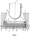
- Figure 1 is a schematic elevational view in section through a vertical plane of the lower part of the reactor vessel well and of the device for recovering and cooling the molten core.
- FIG. 2 is a perspective view of the metal structure of the device for recovering the molten core shown in FIG. 1.
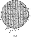
- FIG. 3 is a top view of the metal structure shown in FIG. 2.
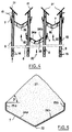
- Figure 4 is a partial sectional view through a vertical plane of the metal structure showing the supports of the hollow profiled elements.
- Figure 5 is a cross-sectional view of a hollow profiled member of the metal structure of the recovery device.
- Figure 6 is a schematic sectional view through a vertical plane of the metal structure of the device recovery, after a spill of corium in the tank well.
- FIG. 1 we see a part of the concrete structure 1 of the nuclear reactor delimiting a vessel well 2 in which the vessel 3 of the reactor containing the core is disposed.
- the tank 3 of generally cylindrical shape is arranged with its axis 4 in the vertical direction and coincides with the axis of the tank well 2.
- the tank 3 is closed at its lower part by a domed bottom 3a of hemispherical shape.
- the tank well 2 comprises a part of frustoconical shape at the bottom of the tank 3a extended by a cylindrical part closed at its lower end by the bottom of the tank well 2a located directly above the tank bottom 3a.
- the metallic structure 5 of the device for recovering and cooling the core of the reactor, in the event of an accident accompanied by a melting of this core, is arranged in the lower cylindrical part of the vessel well and rests on the bottom 2a.
- a circular deflector 6 is arranged around the vessel well, at the lower end of the frustoconical part connecting to the upper part of the cylindrical part in which the metal structure 5 is arranged.
- the deflector 6 is constituted by a sheet fixed to the interior surface of the vessel well and folded inwards to form a deflecting edge directed towards the metal structure 5 and intended to prevent falls of corium at the external periphery of the metal structure 5, between this metallic structure and the interior surface of the tank well.
- the metal structure 5 is made up of elements profiles 7 of elongated shape, the section visible in Figure 1 has the shape of a V.
- the profiled elements 7 are all mutually parallel and are arranged in successive horizontal overlapping plies in which the profiled elements 7 are spaced laterally by a distance less than the total width of a profile 7.
- the profiled elements 7 of two successive layers are staggered and, due to their lateral spacing less than the width of a profile, overlap slightly along their lateral edges, as will be explained below.
- the profiled elements 7 arranged horizontally and whose V-shaped section is flared and open upward constitute gutters making it possible to collect the reactor core and the materials of the molten tank entrained by the core, following an accident resulting in a total reactor cooling defect.
- the profiled elements 7 are held by vertical supports 8 which are formed by hollow columns which will be described later.
- the metal structure 5 comprises six superimposed horizontal plies 9a, 9b, 9c, 9d, 9e and 9f in which the profiled elements 7 are held by the tubular columns 8 in parallel and spaced arrangements, as shown above.
- references 9a, ... 9f corresponding to the different plies of the metal structure 5 designate the first element 7 on the right of each of the plies.
- the profiled elements 7 are obtained by longitudinal folding of a rectangular sheet, so that the profiled element has two inclined faces forming an angle close to 120 ° between them.
- the profiled elements of the two lower plies 9e and 9f are produced by a simple longitudinal folding of the sheet and have only two inclined faces while the profiled elements of the upper plies 9a, 9b, 9c and 9d also have two edges raised at the vertical at the end of each of their inclined faces.
- the profiled elements 7 of the different successive layers overlap laterally, so that the whole of the structure 5 constitutes a surface for collecting the corium occupying the entire section of the well of the vessel.
- the profiled elements 7 have decreasing lengths from the central part of the structure 5, towards the lateral ends of this structure.
- the inclined faces of the elements 7 are pierced with openings allowing the passage of the holding columns 8 which are welded to the metal elements at the crossing openings.
- the metal elements such as 7a, 7b, 7c arranged in the vicinity of the center of the structure 5 comprise four sets of two openings distributed along their length, each allowing the passage of two holding columns 8.
- the elements of shorter length such as elements 7d and 7e located in the vicinity of the lateral ends of the structure have only two sets of two openings each allowing the passage and the fixing of two support columns.
- the columns 8 are arranged in six rows of unequal lengths in directions perpendicular to the profiled elements 7.
- the profiled elements 7 in the form of a gutter are closed at their ends by walls of triangular shape 10, some of which have been shown in FIGS. 1 and 2.
- each of the columns 8 crosses the inclined faces of a series of superimposed profiled elements belonging to each of the six horizontal plies 9a to 9f successive. In this way, the assembly and the rigidity of the entire metal structure 5 are ensured.
- the metal structure 5 is supported on the bottom of the tank well 2a, via the lower ends of the columns 8, so that the structure 5 rests in an extremely stable manner on the bottom of the tank well 2a.
- the tank well 2 is filled with water up to a level 12 situated above the upper level of the metal structure 5.
- the metal structure 5 is fixed inside the tank well 2 by anchors such as 13 welded to the external part of the structure 5 and sealed in the concrete of the wall 1 of the tank well 2.
- the profiled elements 7 of the successive rows arranged in staggered rows are assembled together and held in place by tubular columns 8 passing through the wall of the inclined faces of the profiled elements 7 and assembled by welding on these walls.
- the columns 8 have two pairs of through openings 14 and 15 at their lower part and at their upper part respectively.
- the two pairs of openings are offset according to the height of the column 8 and arranged at 90 ° from one another, so as to promote the circulation of water in column 8.
- the structure 5 is in fact immersed in a body of water filling the bottom of the reactor vessel well and in the event of an accident resulting in a melting of the core and a spillage of the corium on the structure, the water vaporized on contact corium is replaced by water introduced by a pipe 18 opening into the tank well ( Figure 1).
- the cooling water filling the bottom of the vessel well circulates, during the cooling of the corium, in the vertical direction both outside the columns 8 (arrows 20) and inside the support columns 8 (arrows 19).
- Deflector protection plates 21 are fixed to the upper end of the support columns 8, in inclined positions, in order to prevent a spillage of corium inside the support columns 8 and to direct the molten corium towards the inner surface of the profiled elements 7 in the form of a gutter.
- a profiled element 7 of one of the upper rows 9a to 9d of the metallic structure is seen.
- This profiled element 7 is constituted by a sheet of rectangular shape folded along its median to form the lower edge 22 of the profiled element in the form of a gutter.
- the profiled element 7 has two inclined faces 24a and 24b constituting a dihedral whose angle is close to 120 °.
- the faces 24a and 24b are folded in the vertical direction near their outer edge to form two raised edges 25a and 25b allowing to increase the retention capacity of the corium, of the profiled element 7 in the form of a gutter.
- the profiled elements 7 in the form of a gutter are reinforced and stiffened by V-shaped parts 26 conforming to the external shape of the profiled element 7.
- V-shaped reinforcing pieces 26 are fixed to the profiled elements at the level of the columns 8 and make it possible to strengthen the connection between the profiled element 7 and the column 8.
- the profiled elements 7 constitute receptacles intended to collect the corium 27 capable of spilling onto the metallic structure 5 in the event of an accident resulting in the melting of the reactor core.
- the corium 27 Given the viscosity of the corium at its discharge temperature, the corium 27 forms a heap inside the profiled element 7 whose slope angle ⁇ is close to 45 °.
- the inclined faces 24a and 24b of the profiled elements 7 arranged in successive horizontal plies overlap laterally, so that the external lateral part of the inclined faces is located at the vertical alignment of the external lateral part of inclined faces of the profiled elements located in the other layers of the metal structure 5.
- the total capacity for retaining the corium by the profiled elements 7 is calculated and fixed at a value greater than the total mass of the corium which can be discharged into the vessel well.
- the very high temperature corium retained by the profiled elements 7, as shown in FIG. 6, is cooled by the water filling the bottom of the tank well which evaporates and which is replaced by water introduced into the bottom from the vessel well via line 18.
- the water thus circulates in the vertical direction (arrows 20 in FIGS. 4 and 6) coming into contact with the inclined lower faces 24a and 24b of the elements 7.
- the water heats up and vaporizes, the vapor is evacuated by the upper part of the cell well and replacement water is injected through the lower part of the cell well. This results in an intense and rapid circulation of water in contact with the profiled elements 7 of the metal structure 5.
- the water also ensures the cooling of the support columns 8 of the structure, as indicated above.
- profiled elements and the vertical supports of these profiled elements can have different shapes and arrangements from those which have been described.
- the metallic structure may include any number of horizontal plies superimposed on metallic elements, this structure having to comprise at least two plies making it possible to ensure complete covering of the section of the tank well.
- the invention applies to any nuclear reactor comprising a vessel containing the reactor core placed inside a vessel well.
Landscapes
- Physics & Mathematics (AREA)
- Engineering & Computer Science (AREA)
- Plasma & Fusion (AREA)
- General Engineering & Computer Science (AREA)
- High Energy & Nuclear Physics (AREA)
- Structure Of Emergency Protection For Nuclear Reactors (AREA)
Applications Claiming Priority (2)
| Application Number | Priority Date | Filing Date | Title |
|---|---|---|---|
| FR9115028 | 1991-12-04 | ||
| FR9115028A FR2684790B1 (fr) | 1991-12-04 | 1991-12-04 | Reacteur nucleaire comportant un dispositif de recuperation et de refroidissement du cóoeur du reacteur en fusion a la suite d'un accident. |
Publications (2)
| Publication Number | Publication Date |
|---|---|
| EP0545767A1 true EP0545767A1 (de) | 1993-06-09 |
| EP0545767B1 EP0545767B1 (de) | 1995-05-03 |
Family
ID=9419665
Family Applications (1)
| Application Number | Title | Priority Date | Filing Date |
|---|---|---|---|
| EP92403140A Expired - Lifetime EP0545767B1 (de) | 1991-12-04 | 1992-11-20 | Kernreaktor mit einer Vorrichtung zum Auffangen und Kühlen von geschmolzenen Spaltzonenmassen als Folge eines Unfalles |
Country Status (3)
| Country | Link |
|---|---|
| EP (1) | EP0545767B1 (de) |
| DE (1) | DE69202326T2 (de) |
| FR (1) | FR2684790B1 (de) |
Cited By (8)
| Publication number | Priority date | Publication date | Assignee | Title |
|---|---|---|---|---|
| DE4339904A1 (de) * | 1993-06-08 | 1994-12-15 | Siemens Ag | Vorrichtung zum Rückhalten einer heißen Schmelze, insbesondere einer Kernschmelze innerhalb der Ausbreitungskammer einer Kernreaktoranlage |
| DE19638980C1 (de) * | 1996-09-23 | 1998-04-30 | Siemens Ag | Auffangeinrichtung zur Aufnahme hocherhitzter, zumindest teilweise fließfähiger Materialien, wie z. B. Flüssigkeiten, Schlacken, Schmelzen und dgl., insbesondere Schmelzeauffängereinrichtung für Kernkraftwerke |
| EP0947996A1 (de) * | 1998-03-31 | 1999-10-06 | Siempelkamp Guss- und Anlagentechnik Holding GmbH & Co. | Auffanglager für Kernschmelze |
| US6192097B1 (en) | 1993-11-23 | 2001-02-20 | Siemens Aktiengesellschaft | Device for retaining a hot melt in particular a core melt-through inside the spreading chamber of a nuclear reactor installation |
| RU2168217C2 (ru) * | 1996-09-24 | 2001-05-27 | Чехонадских Александр Михайлович | Препятствие перемещению расплавленных материалов активной зоны ядерного реактора |
| JP2015203590A (ja) * | 2014-04-11 | 2015-11-16 | 日立Geニュークリア・エナジー株式会社 | 床材ユニット |
| JP2016011902A (ja) * | 2014-06-30 | 2016-01-21 | 株式会社東芝 | 原子炉格納容器底部保護装置および原子炉格納設備 |
| JP2016191559A (ja) * | 2015-03-30 | 2016-11-10 | 日立Geニュークリア・エナジー株式会社 | コアキャッチャ |
Citations (4)
| Publication number | Priority date | Publication date | Assignee | Title |
|---|---|---|---|---|
| FR2241850A1 (de) * | 1973-08-24 | 1975-03-21 | Atomic Energy Authority Uk | |
| EP0105800A1 (de) * | 1982-09-30 | 1984-04-18 | Commissariat A L'energie Atomique | Protektionsstruktur des Bodens einer Betonhülle |
| WO1990010936A1 (en) * | 1989-03-10 | 1990-09-20 | Becker Kurt M | An arrangement for protecting reactor containment integrity |
| EP0392604A1 (de) * | 1989-04-13 | 1990-10-17 | Ente Nazionale Per L'energia Elettrica - (Enel) | Schutzsystem für das Reaktorschutzgebäude in einer Kernkraftwerksanlage |
-
1991
- 1991-12-04 FR FR9115028A patent/FR2684790B1/fr not_active Expired - Fee Related
-
1992
- 1992-11-20 DE DE69202326T patent/DE69202326T2/de not_active Expired - Fee Related
- 1992-11-20 EP EP92403140A patent/EP0545767B1/de not_active Expired - Lifetime
Patent Citations (4)
| Publication number | Priority date | Publication date | Assignee | Title |
|---|---|---|---|---|
| FR2241850A1 (de) * | 1973-08-24 | 1975-03-21 | Atomic Energy Authority Uk | |
| EP0105800A1 (de) * | 1982-09-30 | 1984-04-18 | Commissariat A L'energie Atomique | Protektionsstruktur des Bodens einer Betonhülle |
| WO1990010936A1 (en) * | 1989-03-10 | 1990-09-20 | Becker Kurt M | An arrangement for protecting reactor containment integrity |
| EP0392604A1 (de) * | 1989-04-13 | 1990-10-17 | Ente Nazionale Per L'energia Elettrica - (Enel) | Schutzsystem für das Reaktorschutzgebäude in einer Kernkraftwerksanlage |
Cited By (8)
| Publication number | Priority date | Publication date | Assignee | Title |
|---|---|---|---|---|
| DE4339904A1 (de) * | 1993-06-08 | 1994-12-15 | Siemens Ag | Vorrichtung zum Rückhalten einer heißen Schmelze, insbesondere einer Kernschmelze innerhalb der Ausbreitungskammer einer Kernreaktoranlage |
| US6192097B1 (en) | 1993-11-23 | 2001-02-20 | Siemens Aktiengesellschaft | Device for retaining a hot melt in particular a core melt-through inside the spreading chamber of a nuclear reactor installation |
| DE19638980C1 (de) * | 1996-09-23 | 1998-04-30 | Siemens Ag | Auffangeinrichtung zur Aufnahme hocherhitzter, zumindest teilweise fließfähiger Materialien, wie z. B. Flüssigkeiten, Schlacken, Schmelzen und dgl., insbesondere Schmelzeauffängereinrichtung für Kernkraftwerke |
| RU2168217C2 (ru) * | 1996-09-24 | 2001-05-27 | Чехонадских Александр Михайлович | Препятствие перемещению расплавленных материалов активной зоны ядерного реактора |
| EP0947996A1 (de) * | 1998-03-31 | 1999-10-06 | Siempelkamp Guss- und Anlagentechnik Holding GmbH & Co. | Auffanglager für Kernschmelze |
| JP2015203590A (ja) * | 2014-04-11 | 2015-11-16 | 日立Geニュークリア・エナジー株式会社 | 床材ユニット |
| JP2016011902A (ja) * | 2014-06-30 | 2016-01-21 | 株式会社東芝 | 原子炉格納容器底部保護装置および原子炉格納設備 |
| JP2016191559A (ja) * | 2015-03-30 | 2016-11-10 | 日立Geニュークリア・エナジー株式会社 | コアキャッチャ |
Also Published As
| Publication number | Publication date |
|---|---|
| DE69202326D1 (de) | 1995-06-08 |
| FR2684790A1 (fr) | 1993-06-11 |
| DE69202326T2 (de) | 1995-11-02 |
| FR2684790B1 (fr) | 1994-03-18 |
| EP0545767B1 (de) | 1995-05-03 |
Similar Documents
| Publication | Publication Date | Title |
|---|---|---|
| EP0514243B1 (de) | Vorrichtungen zum Auffangen und Kühlen eines geschmolzenen Kerns eines Kernreaktors nach einem Unfall | |
| EP0023742B1 (de) | Gestell zur Lagerung von Kernbrennelementenbündeln | |
| EP0058615B1 (de) | Stossdämpfungsanordnung gegen durch schwere Gegenstände erzeugte Stösse | |
| FR2784785A1 (fr) | Reacteur nucleaire a eau equipe d'un receptacle contenant des structures internes deformables | |
| EP0533529B1 (de) | Betonstrukturschutz- und Kühlvorrichtung eines Kernreaktores, dessen Spaltzone nach einem Unfall eine Schmelzung erfährt | |
| EP0545767B1 (de) | Kernreaktor mit einer Vorrichtung zum Auffangen und Kühlen von geschmolzenen Spaltzonenmassen als Folge eines Unfalles | |
| EP0105800B1 (de) | Protektionsstruktur des Bodens einer Betonhülle | |
| FR2683375A1 (fr) | Reacteur nucleaire equipe d'un dispositif de recuperation du cóoeur, apres sa fusion accidentelle. | |
| EP0434510A1 (de) | Anordnung zur Stoffverteilung sowie zum Wärme- und Stoffaustausch für eine Kolonne, insbesondere mit Füllkörper und Kolonne mit einer solchen Anordnung | |
| FR2509899A1 (fr) | Support de stockage pour assemblages combustibles epuises de reacteurs nucleaires | |
| EP0907187A1 (de) | Wasserkernreaktor dessen Druckgefäss eine Auffangvorrichtung der Spaltzone nach einem Schmelzunfall enthält | |
| EP0324807B1 (de) | Vorrichtung zur verhinderung des eindringens einer kernreaktorcorschmelze in das erdreich | |
| EP0762431B1 (de) | Einrichtung und Verfahren zum Auffangen und Kühlen der Kernschmelze eines Kernreaktors | |
| FR2715760A1 (fr) | Assemblage de combustible incluant des ailettes déflectrices pour dévier une composante d'un courant de fluide s'y écoulant. | |
| EP0561694B1 (de) | Behälter zur Aufnahme einer Flüssigkeit für biologischen Schutz gegen ionisierende Strahlungen, Wand und Verfahren zum Aufbau mit Hilfe dieser Behälter | |
| EP0634607A1 (de) | Dampferzeuger mit abnehmbarem Zyklonabscheidersystem | |
| EP0173586B1 (de) | Wärmetauscher mit Rohrbündel, von einer zylindrischen Hülle umgeben, welche radial in einer äusseren Hülle festgehalten wird | |
| EP0251839B1 (de) | Fallstromverdampfer, ausgerüstet mit einem Flüssigkeitsverteiler | |
| EP0082780B1 (de) | Dampferzeuger durch Wärmeaustauschung zwischen einem flüssigen, kalorienreichen Metall und Speisewasser | |
| EP0086695B1 (de) | Dampferzeuger mit U-Rohrbündel und Überhitzer | |
| EP0246143B1 (de) | Auflagervorrichtung für ein Auslassgehäuse einer in einem Kernreaktor aufgehängten Pumpe | |
| EP0265311A1 (de) | Kühlvorrichtung des Hauptgefässes eines flüssigkeitsmetallgekühlten schnellen Neutronenreaktors | |
| EP0029781A1 (de) | Verschlussvorrichtung zur Begrenzung der Konvektionsströme in einem eine Kernreaktorkomponente umgebenden, ringförmigen Raum | |
| WO2014102499A1 (fr) | Prevention du debordement de liquide en dehors d'une installation a l'air libre de stockage de liquide | |
| FR2643189A1 (fr) | Dispositif de protection thermique de la virole superieure de supportage d'une cuve suspendue, notamment dans un reacteur nucleaire a neutrons rapides |
Legal Events
| Date | Code | Title | Description |
|---|---|---|---|
| PUAI | Public reference made under article 153(3) epc to a published international application that has entered the european phase |
Free format text: ORIGINAL CODE: 0009012 |
|
| AK | Designated contracting states |
Kind code of ref document: A1 Designated state(s): BE CH DE ES GB LI SE |
|
| 17P | Request for examination filed |
Effective date: 19930602 |
|
| 17Q | First examination report despatched |
Effective date: 19940823 |
|
| GRAA | (expected) grant |
Free format text: ORIGINAL CODE: 0009210 |
|
| AK | Designated contracting states |
Kind code of ref document: B1 Designated state(s): BE CH DE ES GB LI SE |
|
| PG25 | Lapsed in a contracting state [announced via postgrant information from national office to epo] |
Ref country code: ES Free format text: THE PATENT HAS BEEN ANNULLED BY A DECISION OF A NATIONAL AUTHORITY Effective date: 19950503 |
|
| REF | Corresponds to: |
Ref document number: 69202326 Country of ref document: DE Date of ref document: 19950608 |
|
| PG25 | Lapsed in a contracting state [announced via postgrant information from national office to epo] |
Ref country code: SE Effective date: 19950803 |
|
| GBT | Gb: translation of ep patent filed (gb section 77(6)(a)/1977) |
Effective date: 19950812 |
|
| PLBE | No opposition filed within time limit |
Free format text: ORIGINAL CODE: 0009261 |
|
| STAA | Information on the status of an ep patent application or granted ep patent |
Free format text: STATUS: NO OPPOSITION FILED WITHIN TIME LIMIT |
|
| 26N | No opposition filed | ||
| REG | Reference to a national code |
Ref country code: GB Ref legal event code: IF02 |
|
| PGFP | Annual fee paid to national office [announced via postgrant information from national office to epo] |
Ref country code: CH Payment date: 20021101 Year of fee payment: 11 |
|
| PGFP | Annual fee paid to national office [announced via postgrant information from national office to epo] |
Ref country code: GB Payment date: 20021114 Year of fee payment: 11 |
|
| PGFP | Annual fee paid to national office [announced via postgrant information from national office to epo] |
Ref country code: DE Payment date: 20021202 Year of fee payment: 11 |
|
| PGFP | Annual fee paid to national office [announced via postgrant information from national office to epo] |
Ref country code: BE Payment date: 20021204 Year of fee payment: 11 |
|
| PG25 | Lapsed in a contracting state [announced via postgrant information from national office to epo] |
Ref country code: GB Free format text: LAPSE BECAUSE OF NON-PAYMENT OF DUE FEES Effective date: 20031120 |
|
| PG25 | Lapsed in a contracting state [announced via postgrant information from national office to epo] |
Ref country code: LI Free format text: LAPSE BECAUSE OF NON-PAYMENT OF DUE FEES Effective date: 20031130 Ref country code: CH Free format text: LAPSE BECAUSE OF NON-PAYMENT OF DUE FEES Effective date: 20031130 Ref country code: BE Free format text: LAPSE BECAUSE OF NON-PAYMENT OF DUE FEES Effective date: 20031130 |
|
| BERE | Be: lapsed |
Owner name: *FRAMATOME Effective date: 20031130 |
|
| PG25 | Lapsed in a contracting state [announced via postgrant information from national office to epo] |
Ref country code: DE Free format text: LAPSE BECAUSE OF NON-PAYMENT OF DUE FEES Effective date: 20040602 |
|
| GBPC | Gb: european patent ceased through non-payment of renewal fee |
Effective date: 20031120 |
|
| REG | Reference to a national code |
Ref country code: CH Ref legal event code: PL |