EP0546221B1 - Ballonkatheter - Google Patents
Ballonkatheter Download PDFInfo
- Publication number
- EP0546221B1 EP0546221B1 EP91203259A EP91203259A EP0546221B1 EP 0546221 B1 EP0546221 B1 EP 0546221B1 EP 91203259 A EP91203259 A EP 91203259A EP 91203259 A EP91203259 A EP 91203259A EP 0546221 B1 EP0546221 B1 EP 0546221B1
- Authority
- EP
- European Patent Office
- Prior art keywords
- lumen
- guide wire
- balloon
- catheter
- shaft
- Prior art date
- Legal status (The legal status is an assumption and is not a legal conclusion. Google has not performed a legal analysis and makes no representation as to the accuracy of the status listed.)
- Expired - Lifetime
Links
Images


Classifications
-
- A—HUMAN NECESSITIES
- A61—MEDICAL OR VETERINARY SCIENCE; HYGIENE
- A61M—DEVICES FOR INTRODUCING MEDIA INTO, OR ONTO, THE BODY; DEVICES FOR TRANSDUCING BODY MEDIA OR FOR TAKING MEDIA FROM THE BODY; DEVICES FOR PRODUCING OR ENDING SLEEP OR STUPOR
- A61M29/00—Dilators with or without means for introducing media, e.g. remedies
- A61M29/02—Dilators made of swellable material
-
- A—HUMAN NECESSITIES
- A61—MEDICAL OR VETERINARY SCIENCE; HYGIENE
- A61M—DEVICES FOR INTRODUCING MEDIA INTO, OR ONTO, THE BODY; DEVICES FOR TRANSDUCING BODY MEDIA OR FOR TAKING MEDIA FROM THE BODY; DEVICES FOR PRODUCING OR ENDING SLEEP OR STUPOR
- A61M25/00—Catheters; Hollow probes
- A61M25/01—Introducing, guiding, advancing, emplacing or holding catheters
- A61M2025/0183—Rapid exchange or monorail catheters
Definitions
- the invention relates to a balloon catheter with a shaft, on the distal end of which a balloon is attached, the shaft having a lumen through which the balloon is fed and a lumen through which a guide wire is guided, with which the catheter is guided and controlled, the shaft consists of a proximal and a distal area, the shaft in the proximal area being made of a stiffer material and the lumen for the guide wire being guided coaxially in the shaft, so that the lumen for balloon feeding surrounds the lumen for the guide wire in an annular manner, and wherein in the distal area of the shaft, the shaft is made of a more flexible material, and the lumens for balloon feeding and for wire guidance lie biaxially next to each other.
- a balloon catheter of this type is known for example from DE GM 91 06 499.
- the balloon catheter shown there is used together with a guide catheter and a guide wire for percutaneous transluminal coronary recanalization.
- the catheter is inserted through a puncture into the skin into a blood vessel and advanced over the blood vessel until, for example, an arteriosclerotic narrowing in the coronary arteries.
- the refillable balloon is then expanded using the inflatable balloon at the end of the catheter.
- the shaft of this known catheter is composed of two lengths.
- the operator-side, proximal length is made of a particularly rigid material and is also coaxial, i.e. H. constructed according to the "hose in hose” system. This leads to a particularly stiff shaft in this area.
- the distal shaft length which is remote from the operator, is made of a particularly flexible material and is constructed in such a way that the two lumens in the shaft, the channel for balloon feeding and the channel for receiving the guide wire, are in a common shaft sleeve lie side by side.
- This design results in a more flexible design, so that both measures together, flexible material and more flexible design, result in a shaft that softly adapts to all blood vessel shapes.
- This arrangement is intended to ensure that on the one hand the distal end of the catheter with the folded-up balloon can be easily inserted into the tortuous passages of the coronary arteries, but on the other hand that the pushing forces for advancing the catheter are well transmitted in the proximal, rigid section of the shaft.
- the shaft deflects to the side when the catheter is advanced under the thrust forces, and particularly high frictional forces arise between the catheter and the side wall where the catheter deflects to the side.
- Part of the thrust force introduced into the shaft is thereby lost and is no longer at the tip e.g. available for piercing a vascular occlusion.
- part of the tactile sensation for the attending physician is lost, because part of the resistance that the doctor feels when advancing the catheter is due to uncontrolled frictional forces and not, for example, to resistance that the doctor should take into account during his treatment.
- a catheter of this type can also be used according to the so-called “monorail” system.
- the guide wire which is guided from the tip inside the catheter, does not emerge from the shaft only at the end of the catheter on the operating side, but in a specific shorter distance from the balloon. This makes it easier to replace a catheter while the guide wire remains in the blood vessel with its end behind the constriction. Without this exit opening at a short distance from the balloon, without the "monorail” system, the guide wire must protrude at least the entire length of the catheter from the patient.
- the guide wire can be significantly shorter and changing the catheter is correspondingly easier and faster. The operational effort involved in keeping the guide wire protruding from the patient sterile is less, and the catheter does not have to be pushed over an approximately 3 meter long guide wire.
- EP-A-0 441 384 shows a catheter with a "monorail" exit opening in the shaft of the catheter. It is not a shaft composed of two lengths of different stiffness. A stiffening wire has to be inserted into the catheter in order to achieve a graded stiffness with this shaft. This leads to additional effort for the stiffening wire, its assembly and for a sealing plug at the end of the lumen in which the stiffening wire lies. In addition, the corresponding lumen is no longer available for other purposes, e.g. Drug transport or pressure measurement.
- the object of the invention is to provide a balloon catheter of the type mentioned at the beginning which is simple to produce and can be used universally and which can be used according to the "monorail" system, but whose shaft stiffness is weakened as little as possible by the exit opening required for the guide wire .
- the opening for the guide wire causes the least possible weakening of the catheter shaft.
- the fact that only one wall has to be pierced to make an opening makes it easier to make a through opening for the guide wire, but a larger hole in the shaft there is a sensitive disturbance of the shaft structure.
- the shaft structure present there and the chosen soft for this area Material the shaft has its least stiffness there.
- the opening is carried out in the coaxial area.
- the material of the shaft is stiffer and therefore more resistant to buckling and the shaft structure is more stable due to the fact that four walls are available in the longitudinal section.
- Another advantage is that in this arrangement the passage for the guide wire is located proximal to the kink-sensitive connection point between the proximal and distal shaft. This means that the guidewire is still available as an additional stiffener for this endangered area. It bridges the critical transition from the flexible to the rigid shaft area.
- the outlet opening can be enlarged without hesitation to such an extent that the guide wire easily emerges from the opening when threading into the catheter. Then no aids need to be installed in the lumen of the guide wire, which facilitate the exit of the guide wire from the lumen.
- the wall of the guide wire lumen is sealingly connected to the wall of the balloon lumen in the region of the outlet opening for the guide wire, and both the wall of the balloon lumen and the wall of the guide wire lumen are broken through to produce the outlet opening within the sealingly connected segment.
- This creates a particularly easy to manufacture outlet opening the guide wire tube only touches the wall of the shaft instead of breaking through it.
- the strength of the catheter shaft is increased precisely where reinforcement is appropriate because of the outlet opening.
- the invention therefore not only means that a weakening in the already weaker part of the catheter is avoided in connection with the outlet opening, but it also means that a weakening to be expected is compensated for by a reinforcement before it occurs.
- the guide wire lumen extends without interruption from the outermost proximal end of the catheter to the outermost distal end of the catheter.
- This lumen can then advantageously be used in other areas of application, for example to accommodate an additional, removable and.
- U. formable stiffening wire for the transport of liquids such as contrast agents, solutions for reducing blood clotting, etc. and it can be used to take pressure measurements. It is important that this measure offers a possibility without changing the position of the catheter insert a new guidewire if the previous one was accidentally pulled out of the outlet.
- the outlet opening for the guide wire which is made in the coaxial shaft area, adjoins the connection point between the proximal and distal shaft area.
- the measure specified is an advantageous compromise in this respect, since the root of the distal flexible shaft region advantageously remains in use within the guide catheter lying in the aorta and with its end reaching into the mouth of the coronary vessels.
- the arrangement of the outlet opening at the connection point, ie in this position of the catheter within the guide catheter, ensures that the guide wire is always guided, outside the guide catheter in the guide wire lumen, inside the catheter beyond the outlet opening, in the guide catheter.
- a balloon catheter of this type is also easy to manufacture, since the connection of the two tube walls in the coaxial area can be carried out simultaneously with the connection of the coaxial shaft area to the biaxial shaft area.
- the manufacture of the balloon catheter is further simplified. Cutting produces relatively large chips compared to drilling or grinding. Such large chips are easier to dispose of, a aspect that e.g. is important when manufacturing in a clean room.
- a cut in the axial direction creates an elongated oval opening in the shaft, which allows the guide wire to pass through the opening at an angle without the wire being deflected too sharply. By cutting out the cut in both directions, stress peaks in the shaft are avoided.
- FIG. 1 shows a balloon catheter 1 with a shaft 2.
- the proximal end of the catheter on the operator side is designated by 3.
- the distal end of the catheter remote from the operator is designated by 4.
- a balloon 5 is attached to the distal end 4 of the catheter 1 and can be inflated to the full with a liquid.
- the shaft 2 has two channels, generally called lumens, a lumen 6 for balloon feeding (see FIGS. 3 to 6) and a lumen 7 for the guide wire 8.
- the balloon catheter 1 is used together with a guide wire 8.
- the guide wire 8 is first inserted into the blood vessel together with the catheter 1 or in front of the catheter.
- the guide wire 8 is designed to be steerable, i.e. it can have a certain arch shape at the tip or be brought into a certain arch shape by the doctor, into which it returns whenever no force is exerted on it.
- the guide wire is torsionally rigid.
- the guidewire can be advanced in straight sections of the vessel, it can be guided into branches by the specified tip shape, but it can also be reliably guided past branches in the vessel, namely by twisting the proximal end of the wire at the tip of the specified arch shape Wire is twisted away from the junction to the other side of the vessel.
- the guide wire 8 is used in the form shown in FIG. 2 after the one disclosed in EP 0 203 945 so-called "monorail" principle used. This means that the guide wire 8 is viewed from the proximal end 3 of the catheter 1, initially outside the catheter 1 parallel to it.
- the guide wire 8 enters the catheter 1, from there it is guided inside the catheter 1 and it leaves the catheter 1 at the tip 10 of the catheter distally from the balloon 5
- the guide catheter 11 is also visible in FIG. It surrounds the catheter 1 and the guidewire 8 from the outside and serves as a guide for both of them over a longer vascular path.
- the guide catheter 11 surrounds the catheter 1 and the guide wire 8 with an internal rubber seal.
- a lateral connection 12 is attached to the side of the guide catheter 11. It is used to add contrast agents or medication to prevent blood clotting, or to take pressure measurements.
- a branch 13 is attached to the proximal end 3 of the catheter 1.
- a lumen of the catheter 1 is passed sealingly into a connection piece 14.
- the other lumen opens into a sealed space inside the branch 13, from which the second connection 15 extends.
- a removable stiffening wire 16 is inserted into the one lumen via the connection 14. Removable stiffening wires are used to additionally stiffen the proximal area of a catheter, at least as long as the corresponding lumen is not fully used for another task.
- the shaft 2 of the catheter 1 in FIG. 1 is composed of a proximal shaft region 18 and a distal shaft region 19 at a connection point.
- the shaft is made of a stiffer material.
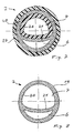
- a cross section through the shaft in the proximal shaft region is shown in FIG. 5.
- the lumen 6, through which the balloon 5 is fed, surrounds the lumen 7 for the guide wire 8 in an annular manner. This construction makes the shaft 2 even more rigid because four walls are thus available in longitudinal section to contribute to the bending stiffness.
- the shaft is made of more flexible material than in the proximal region 18.
- a cross section through the shaft in the distal shaft region 19 is shown in FIG. 8.
- the lumen 6 for balloon feeding and the lumen 7 for receiving the guide wire 8 lie biaxially next to each other with their own axes.
- a common shaft sleeve 20 surrounds one and the other lumen, they are only separated by a partition 21.
- the shaft 2 is further calibrated over a certain length 22 in the distal shaft area, so that the guide wire lumen 7 has a larger diameter there.
- several small holes 23 are made in the shaft 2, which lead into the guide wire lumen 7. The holes are kept so small that they do not interrupt the strength of the shaft 2, but at the same time allow enough blood to pass through without leading to blockages.
- the balloon feed lumen 6 is cut open and completely removed, so that only the guide wire lumen 7 is continued from the balloon.
- Gold marks 24 on the shaft within the balloon 5 should clearly show the position of the balloon 5 in the x-ray image.
- the balloon 5 is manufactured separately and subsequently connected to the shaft, for example by welding. Distal from the balloon 5, only the part of the shaft 2 that remains after the removal of the balloon feed lumen 6, the part of the shaft that surrounds the guide wire lumen 7, emerges from the balloon.
- Small holes 25 are again made in this shaft area emerging distally from the balloon 5.
- a certain blood flow is possible through this connection, even if in the guide wire lumen 7 the guide wire 8 is laid.
- the blood flow is increased accordingly when the guide wire 8 is withdrawn from the length 22.
- This blood flow can supply blood to the vessels distal to the balloon. This is an important consideration because it can extend the treatment of the narrowing in the vein without the organs located distally from the balloon suffering from excessive reduction in blood flow.
- a clear distance is maintained between the length 22 and the opening 9, e.g. in the order of half the length of the distal shaft region 19. As a rule, however, it is sufficient if this distance is approximately as long as the length 22 itself.
- connection point 17 between the proximal, stiffer and the distal, more flexible shaft region 18 or 19 can be seen in detail in FIG. 3 and in FIG. 7.
- the inner tube 26 of the coaxial shaft region 18 is inserted into the guide wire lumen 7 of the biaxial distal shaft region 19.
- the guide wire lumen 7 extends without interruption from the outermost proximal end of the catheter 1 to the outermost distal end of the catheter.
- the outer tube 27 is pushed over the shaft sleeve 20 of the biaxial distal shaft region 19.
- the two shaft areas are then connected to one another by means of binders or by welding.
- An advantageous procedure consists in providing the lumens with a filling and surrounding the connection point 17 with a suitable shrink tube. If the shrink tube is selected accordingly, the heat supply for shrinking is just sufficient to compress the two shaft regions when shrinking the shrink tube and to weld them together at the same time. The shrink tube can then be removed again.
- FIGS. 3, 4 and 6 The lateral opening 9 in the shaft 2 for the guide wire 8 is shown in FIGS. 3, 4 and 6 in detail. It is apparent from these drawings that the outlet opening 9 for the guide wire 8 is not arranged in the distal shaft region 19, where the shaft 2 is made biaxially, but rather is arranged in the proximal shaft region 18, in which the shaft 2 is made coaxial and stiffer.
- FIG. 6 shows that in the area of the outlet opening 9 for the guide wire 8, a jacket segment of the wall of the guide wire lumen 7, ie a jacket segment of the inner tube 26, is sealingly connected to the wall of the balloon lumen 6, ie to the outer tube 27.
- both the wall of the balloon lumen 6, the outer tube 27, and the wall of the guide wire lumen 7, the inner tube 26, are pierced by a cut 28.
- the cut 28 is made in the axial direction and penetrates both walls, the wall of the balloon feed lumen and the wall of the guide wire lumen at the same time. It thus results in an elongated oval hole as in the view in FIG. 4.
- the cutout shape produced in this way does not lead to any voltage peaks in the catheter shaft.
- This cut-out shape can be made so large and so long that the guide wire 8 easily emerges from the shaft 1 when it is being threaded into the catheter without the need for outlet aids, such as a ramp or the like, to be arranged in the lumen 7.
- the outlet opening 9 for the guide wire 8 in the coaxial shaft region 18 closes so close to the connection point 17 between proximal and distal shaft region 18, 19 that the connection point 17 and the sealing connection for the outlet opening 9 can be produced in one operation.
Landscapes
- Health & Medical Sciences (AREA)
- Vascular Medicine (AREA)
- Engineering & Computer Science (AREA)
- Anesthesiology (AREA)
- Biomedical Technology (AREA)
- Heart & Thoracic Surgery (AREA)
- Hematology (AREA)
- Life Sciences & Earth Sciences (AREA)
- Animal Behavior & Ethology (AREA)
- General Health & Medical Sciences (AREA)
- Public Health (AREA)
- Veterinary Medicine (AREA)
- Media Introduction/Drainage Providing Device (AREA)
- Materials For Medical Uses (AREA)
Description
- Die Erfindung betrifft einen Ballonkatheter mit einem Schaft, an dessen distalem Ende ein Ballon angebracht ist, wobei der Schaft ein Lumen aufweist, durch das der Ballon gespeist wird und ein Lumen durch das ein Führungsdraht geführt wird, mit dem der Katheter geführt und gesteuert wird, dabei besteht der Schaft aus einem proximalen und einem distalen Bereich, wobei im proximalen Schaftbereich der Schaft aus einem steiferen Material hergestellt ist und das Lumen für den Führungsdraht koaxial im Schaft geführt ist, sodass das Lumen zur Ballonspeisung das Lumen für den Führungsdraht ringförmig umgibt und wobei im distalen Schaftbereich der Schaft aus einem flexibleren Material hergestellt ist, und die Lumen zur Ballonspeisung und zur Drahtführung biaxial nebeneinander liegen.
- Ein Ballonkatheter dieser Art ist beispielsweise aus der DE GM 91 06 499 bekannt. Der dort gezeigte Ballonkatheter wird zusammen mit einem Führungskatheter und einem Führungsdraht zur perkutanen transluminalen Koronar-Rekanalisation benutzt. Der Katheter wird durch einen Einstich in die Haut in ein Blutgefäss eingeführt und über das Blutgefäss bis zu einer beispielsweise arteriosklerotischen Verengung in den Herzkranzgefässen vorgeschoben. Mit dem auffüllbaren Ballon am Ende des Katheters wird die Verengung dann aufgeweitet.
- Der Schaft dieses bekannten Katheters ist aus zwei Längen zusammengesetzt. Die bedienungsseitige, proximale Länge ist aus einem besonders steifen Material hergestellt und ausserdem koaxial, d. h. nach dem System "Schlauch im Schlauch" aufgebaut. Das führt zu einem besonders steifen Schaft in diesem Bereich.
- Die bedienungsferne, die distale Schaftlänge ist aus besonders flexiblem Material hergestellt und so aufgebaut, dass die beiden Lumen im Schaft, der Kanal zur Ballonspeisung und der Kanal zur Aufnahme des Führungsdrahtes, in einer gemeinsamen Schafthülle nebeneinander liegen. Diese Bauweise ergibt eine flexiblere Konstruktion, sodass beide Massnahmen zusammen, nachgiebiges Material und flexiblere Bauweise, einen Schaft ergeben, der weich sich allen Blutgefässformen anpasst.
- Mit dieser Anordnung soll erreicht werden, dass einerseits das distale Ende des Katheters mit dem zusammengefalteten Ballon sich leicht in die gewundenen Gänge der Herzkranzgefässe einführen lässt, dass andererseits aber gleichzeitig im proximalen, steifen Abschnitt des Schaftes die Schubkräfte zum Vorschieben des Katheters gut übertragen werden.
- Wenn der proximale Abschnitt nicht steif genug ist, dann weicht der Schaft beim Vorschieben des Katheters unter den Schubkräften zur Seite hin aus und es entstehen dort, wo der Katheter zur Seite hin ausweicht, besonders hohe Reibungskräfte zwischen Katheter und Seitenwand. Ein Teil der in den Schaft eingebrachten Schubkraft geht dadurch verloren und steht an der Spitze nicht mehr z.B. zum Durchstossen eines Gefässverschlusses zur Verfügung. Dadurch geht auch ein Teil des Tastgefühls für den behandelnden Arzt verloren, indem nämlich ein Teil der Widerstände, die der Arzt beim Vorschieben des Katheters spürt, auf unkontrollierte Reibkräfte zurückzuführen ist und nicht etwa auf Widerstände, die der Arzt bei seiner Behandlung berücksichtigen müsste. Auch legt durch dieses seitliche Ausweichen des Katheterschaftes beim Vorschieben des Katheters die Spitze des Katheters, der Ballon, nicht mehr den gleichen Weg zurück wie das bedienungsseitige Ende. Die Sicherheit und Zuverlässigkeit, mit der der Arzt den Katheter führen kann, erleidet dadurch erhebliche Einbussen.
- Es ist wünschenswert, dass ein Katheter dieser Art auch nach dem sogenannten "Monorail"-System eingesetzt werden kann. Bei diesem in der EP 0 203 945 beschriebenen System tritt der von der Spitze an innerhalb des Katheters geführte Führungsdraht nicht erst am bedienungsseitigen Ende des Katheters aus dem Schaft aus, sondern in einem bestimmten, kürzeren Abstand vom Ballon. Das Auswechseln eines Katheters während der Führungsdraht im Blutgefäss mit seinem Ende hinter der Verengung liegen bleibt, ist damit erleichtert. Ohne diese Austrittsöffnung in kurzem Abstand vom Ballon, ohne das "Monorail"-System, muss der Führungsdraht mindestens die gesamte Katheterlänge aus dem Patienten herausragen. Mit dem "Monorail"-System kann der Führungsdraht deutlich kürzer sein und ein Katheterwechsel geht entsprechend einfacher und schneller. Der bedienungsmässige Aufwand, den aus dem Patienten herausstehenden Führungsdraht steril zu halten ist geringer, und der Katheter muss nicht über einen ca. 3 Meter langen Führungsdraht geschoben werden.
- Die EP-A-0 441 384 zeigt einen Katheter mit einer "Monorail"-Austrittsöffnung im Schaft des Katheters. Es handelt sich dabei nicht um einen aus zwei Längen verschiedener Steifigkeit zusammengesetzten Schaft. Um bei diesem Schaft eine abgestufte Steifigkeit zu erreichen, muss ein Versteifungsdraht in den Katheter eingeschoben werden. Das führt zu einem zusätzlichen Aufwand für den Versteifungsdraht, seine Montage und für einen Verschlusstopfen am Ende des Lumens in dem der Versteifungsdraht liegt. Ausserdem steht dadurch das entsprechende Lumen nicht mehr für andere Zwecke zur Verfügung, wie z.B. Medikamententransport oder Druckmessung.
- Die Erfindung hat sich die Aufgabe gestellt, einen einfach herzustellenden und universell verwendbaren Ballonkatheter der eingangs genannten Art zur Verfügung zu stellen, der nach dem "Monorail"-System einsetzbar ist, dessen Schaftsteifigkeit aber durch die dann notwendige Austrittsöffnung für den Führungsdraht möglichst wenig geschwächt wird.
- Diese Aufgabe wird durch den in Anspruch 1 definierten Ballonkatheter gelöst.
- Dadurch wird erreicht, dass der Katheter nach dem "Monorail"-System einsetzbar ist. Gleichzeitig wird erreicht, dass die Öffnung für den Führungsdraht die geringst mögliche Schwächung des Katheterschaftes verursacht. Im biaxialen Schaftbereich ist zwar dadurch, dass zur Herstellung einer Öffnung nur eine Wand zu durchstossen ist, eine Durchgangsöffnung für den Führungsdraht leichter herzustellen, dafür stellt aber dort ein grösseres Loch im Schaft eine empfindliche Störung der Schaftstruktur dar. Wegen des dort vorliegenden Schaftaufbaus und dem für diesen Bereich gewählten weichen Material hat der Schaft dort seine geringste Steifigkeit. Durch die Anbringung einer Öffnung in der Schaftstruktur dieses Bereiches würde die Steifigkeit des Schaftes gerade in dem Bereich weiter herabgesetzt, in dem die Steifigkeit ohnehin ihr niedrigstes Niveau hat. Der Schaft knickt dann an dieser Stelle, und es können ernste Probleme auftreten beim Zurückziehen des Katheters aus dem Gefäss. Anstatt im biaxialen Schaftbereich, wo die Öffnung leichter herzustellen wäre, wird die Öffnung aber im koaxialen Bereich durchgeführt. Dort ist das Material des Schaftes steifer und damit widerstandsfähiger gegen Knicken und die Schaftstruktur ist, dadurch dass im Längsschnitt vier Wandungen zur Verfügung stehen stabiler. Ein weiterer Vorteil liegt noch darin, dass bei dieser Anordnung der Durchlass für den Führungsdraht proximal der knickempfindlichen Verbindungsstelle zwischen proximalem und distalem Schaft liegt. Das bedeutet, dass der Führungsdraht noch als zusätzliche Versteifung dieser gefährdeten Stelle zur Verfügung steht. Er überbrückt den kritischen Übergang des flexiblen zum steifen Schaftbereich.Schliesslich ergibt sich noch ein Vorteil daraus, dass bei der erfindungsgemässen Anordnung die Austrittöffnung ohne Bedenken soweit vergrössert werden kann, dass der Führungsdraht beim Einfädeln in den Katheter leicht aus der Öffnung austritt. Im Lumen des Führungsdrahtes brauchen dann keine Hilfen eingebaut werden, die den Austritt des Führungsdrahtes aus dem Lumen erleichtern.
- Erfindungsgemäß ist im Bereich der Austrittsöffnung für den Führungsdraht die Wandung des Führungsdrahtlumens mit der Wandung des Ballonlumens abdichtend verbunden, und zur Herstellung der Austrittsöffnung innerhalb des abdichtend verbundenen Segmentes sind sowohl die Wandung des Ballonlumens als auch die Wandung des Führungsdrahtlumens durchbrochen. Dadurch entsteht eine besonders einfach herstellbare Austrittsöffnung, der Führungsdrahtschlauch berührt nur die Wandung des Schaftes anstatt sie zu durchbrechen. Gleichzeitig wird durch die Verdopplung der Wandstärke in dem Berührungsbereich die Festigkeit des Katheterschaftes gerade dort verstärkt, wo wegen der Austrittsöffnung eine Verstärkung angebracht ist. Die Erfindung bedeutet also nicht nur, dass in Zusammenhang mit der Austrittsöffnung eine Schwächung im bereits schwächeren Teil des Katheters vermieden wird, sondern sie bedeutet darüber hinaus, dass eine zu erwartende Schwächung vor ihrem Entstehen durch eine Verstärkung kompensiert wird.
- In einer Ausführungsform der Erfindung erstreckt sich das Führungsdrahtlumen ohne Unterbrechung vom äussersten proximalen Ende des Katheters bis zum äussersten distalen Ende des Katheters. Dieses Lumen kann dann vorteilhaft in anderen Anwendungsbereichen noch benutzt werden, z.B. zur Aufnahme eines zusätzlichen, herausnehmbaren u. U. formbaren Versteifungsdrahtes, zum Transport von Flüssigkeiten wie Kontrastmittel, Lösungen zur Reduzierung der Blutgerinnung u. a. und es kann zur Abnahme von Druckmessungen benutzt werden. Wichtig ist, dass mit dieser Massnahme eine Möglichkeit gegeben ist, ohne Lageveränderung des Katheters einen neuen Führungsdraht zu legen, wenn der vorher benutzte versehentlich aus der Austrittsöffnung herausgezogen wurde.
- In einer weiteren besonderen Ausführungsform schliesst die im koaxialen Schaftbereich ausgeführte Austrittsöffnung für den Führungsdraht sich an die Verbindungsstelle zwischen proximalem und distalem Schaftbereich an. Diese Massnahme führt dazu, dass das "Monorail"-Führungsdrahtlumen, das Führungdrahtlumen zwischen Austrittsöffnung und distalem Katheterende, relativ kurz bleibt. Die Entwicklung von immer dünneren Ballonkathetern und immer flexibleren distalen Katheterbereichen führt zwar dazu, dass immer ferner liegende Verengungen in den Blutgefässen behandelt werden. Das wiederum führt dazu, dass die distalen flexibleren Katheterbereiche der Katheter immer länger ausgeführt werden. Es liegt aber im Interesse der eingangs erwähnten leichten Handhabung mit Hilfe des "Monorail"-Systems, wenn das "Monorail"-Führungsdrahtlumen relativ kurz bleibt. Die angegebene Massnahme ist insofern ein vorteilhafter Kompromiss in dieser Frage, als die Wurzel des distalen flexiblen Schaftbereiches im Gebrauch vorteilhafterweise innerhalb des in der Aorta liegenden, mit seinem Ende in die Mündung der Herzkranzgefässe reichenden Führungskatheters verbleibt. Die Anordnung der Austrittsöffnung an der Verbindungsstelle, d.h. in dieser Lage des Katheters innerhalb des Führungskatheters, stellt sicher, dass der Führungsdraht immer geführt ist, ausserhalb des Führungskatheters im Führungsdrahtlumen, innerhalb des Katheters jenseits der Austrittsöffnung, im Führungskatheter. Ein Ballonkatheter dieser Art ist auch einfach herzustellen, da die Verbindung der beiden Schlauchwandungen im koaxialen Bereich gleichzeitig mit der Verbindung des koaxialen Schaftbereiches mit dem biaxialen Schaftbereich durchgeführt werden kann.
- Wenn die Austrittsöffnung für den Führungsdraht durch einen in axialer Richtung geführten Schnitt durch beide Wandungen, die Wandung des Ballonspeisungslumens und die Wandung des Führungsdrahtlumens erzeugt wird, vereinfacht sich die Fertigung des Ballonkatheters weiter. Durch Schneiden entstehen relativ grosse Späne, verglichen mit Bohren oder Schleifen. Solche grossen Späne sind leichter zu entsorgen, ein Gesichtspunkt der z.B. bei Fertigung in einem Reinraum ins Gewicht fällt. Durch einen Schnitt in axialer Richtung entsteht eine länglich ovale Öffnung im Schaft, die einen schrägen Durchgang des Führungsdrahtes durch die Öffnung zulässt, ohne dass der Draht eine zu scharfe Umlenkung erfährt. Durch den Auslauf des Schnittes in beiden Richtungen werden Spannungsspitzen im Schaft vermieden.
- Ein besonders angepasstes Verfahren zur Herstellung eines Ballonkatheters nach der Erfindung besteht darin,
- das Führungsdrahtlumen mit einer Füllung zu versehen, die das Lumen im Bereich der vorgesehenen Austrittsöffnung ausfüllt,
- das Ballonspeisungslumen mit einer Füllung zu versehen, die den Schlauch für den Führungsdraht im Bereich der vorgesehenen Austrittsöffnung an die Wandung des Ballonspeisungslumens presst,
- den Schaft im Bereich der vorgesehenen Austrittsöffnung mit einem Schrumpfelement zu umgeben,
- die Schrumpfung des Schrumpfelementes einzuleiten,
- die durch die Füllungen von innen und das Schrumpfelement von aussen gegeneinander gepressten Wandungen des Führungsdrahtlumens und des Ballonspeisungslumens im Bereich der vorgesehenen Austrittsöffnung thermisch oder durch Bindemittel miteinander zu verbinden,
- die Füllungen jeweils wieder zu entfernen und
- die Austrittsöffnung herzustellen, indem die miteinander verbundenen Wandungen des Führungsdrahtlumens und des Ballonlumens beide durchbrochen werden.
- Die Erfindung wird im folgenden anhand eines in den Zeichnungen dargestellten Ausführungsbeispiels näher erläutert. Es zeigen:
- Fig. 1
- eine Ansicht eines Ballonkatheters nach der Erfindung,
- Fig. 2
- eine Ansicht des proximalen Endes eines Ballonkatheters mit Führungskatheter, Führungsdraht und herausnehmbarem Versteifungsdraht,
- Fig. 3
- ein Längsschnitt durch den Schaft des Ballonkatheters in Fig. 1 an der Austrittsöffnung für den Führungsdraht,
- Fig. 4
- eine Ansicht des Schaftes des Ballonkatheters in Fig. 1 im Bereich der Austrittsöffnung für den Führungsdraht,
- Fig. 5
- einen Querschnitt durch den Schaft des Ballonkatheters in Fig. 1 im Bereich des koaxialen Schaftes,
- Fig. 6
- einen Querschnitt durch den Schaft des Ballonkatheters in Fig. 1 im Bereich der Austrittsöffnung für den Führungsdraht,
- Fig. 7
- einen Querschnitt durch den Schaft des Ballonkatheters in Fig. 1 im Bereich der Verbindungsstelle zwischen koaxialem Schaftbereich und biaxialem Schaftbereich,
- Fig. 8
- einen Querschnitt durch den Schaft des Ballonkatheters in Fig. 1 im Bereich des koaxialen Schaftes.
- Fig. 1 zeigt einen Ballonkatheter 1 mit einem Schaft 2. Das bedienungseitige, proximale Ende des Katheters ist mit 3 bezeichnet. Das bedienungsferne, distale Ende des Katheters ist mit 4 bezeichnet.
- Am distalen Ende 4 des Katheters 1 ist ein Ballon 5 angebracht, der mit einer Flüssigkeit prall aufgebläht werden kann. Der Schaft 2 weist dazu zwei, allgemein Lumen genannte Kanäle auf, ein Lumen 6 zur Ballonspeisung (siehe Fig. 3 bis 6) und ein Lumen 7 für den Führungsdraht 8.
- Wie in Fig. 2 dargestellt, wird der Ballonkatheter 1 zusammen mit einem Führungsdraht 8 benutzt. Der Führungsdraht 8 wird zusammen mit dem Katheter 1 oder vor dem Katheter als erstes in das Blutgefäss eingeschoben. Der Führungsdraht 8 ist lenkbar ausgeführt, d.h. er kann eine bestimmte Bogenform an der Spitze aufweisen oder vom Arzt in eine bestimmte Bogenform gebracht werden, in die er, wenn keine Kraft auf ihn einwirkt, immer wieder zurückkehrt. Gleichzeitig ist der Führungdraht torsionssteif. Mit diesen beiden Eigenschaften lässt der Führungsdraht sich in geraden Gefässabschnitten vorschieben, er lässt sich durch die vorgegebene Spitzenform in Abzweigungen hineinlenken, er lässt sich aber auch an Abzweigungen im Gefäss zuverlässig vorbeisteuern, indem nämlich durch Verdrehung des proximalen Drahtendes die vorgegebene Bogenform an der Spitze des Drahtes von der Abzweigung weg zur anderen Gefässeite hin verdreht wird.
- Der Führungdraht 8 wird in der in Fig. 2 gezeigten Verwendungsform nach dem in der EP 0 203 945 offenbarten sogenannten "Monorail"-Prinzip benutzt. Das bedeutet, der Führungsdraht 8 liegt vom proximalen Ende 3 des Katheters 1 ausgehend betrachtet, zunächst ausserhalb des Katheters 1 parallel zu ihm. Bei der Öffnung 9 in Fig. 1 tritt der in Fig. 1 nicht eingezeichnete Führungsdraht 8 in den Katheter 1 ein, er wird von da an innen im Katheter 1 geführt und er verlässt den Katheter 1 an der Spitze 10 des Katheters distal vom Ballon 5. In Fig. 2 ist ausser dem Führungsdraht 8 auch der Führungskatheter 11 sichtbar. Er umgibt den Katheter 1 und den Führungsdraht 8 von aussen und dient beiden über eine längere Gefässstrecke als Führung. An seinem proximalen Ende umgibt der Führungskatheter 11 den Katheter 1 und den Führungsdraht 8 mit einer innen liegenden Gummidichtung. Seitlich am Führungskatheter 11 ist ein seitlicher Anschluss 12 angebracht. Er wird für die Zugabe von Kontrastmitteln oder von Medikamenten zu Verhinderung von Blutgerinnung gebraucht oder er dient zur Abnahme von Druckmessungen.
- Wie sowohl in Fig. 2 und Fig. 1 sichtbar, ist am proximalen Ende 3 des Katheters 1 ein Abzweig 13 angebracht. In diesem Abzweig 13 wird ein Lumen des Katheters 1 abdichtend weitergeführt in ein Anschlusstück 14. Das andere Lumen mündet in einen abgedichteten Raum im Innern des Abzweiges 13, von dem der zweite Anschluss 15 abgeht. In Fig. 2 ist in das eine Lumen über den Anschluss 14 ein herausnehmbarer Versteifungsdraht 16 eingeführt. Herausnehmbare Versteifungsdrähte werden eingesetzt, um den proximalen Bereich eines Katheters zusätzlich zu versteifen, jedenfalls solange das entsprechende Lumen nicht im vollen Umfang für eine andere Aufgabe gebraucht wird.
- Der Schaft 2 des Katheters 1 in Fig. 1 ist an einer Verbindungsstelle aus einem proximalen Schaftbereich 18 und einem distalen Schaftbereich 19 zusammengesetzt. Im proximalen Bereich 18 ist der Schaft aus einem steiferen Material hergestellt. Ein Querschnitt durch den Schaft im proximalen Schaftbereich ist in Fig. 5 dargestellt. Dort wird deutlich, dass in diesem Bereich des Schaftes 2 das Lumen 7 für den Führungsdraht 8 koaxial, nach dem System "Schlauch in Schlauch" im Schaft geführt ist. Das Lumen 6, durch das der Ballon 5 gespeist wird, umgibt ringförmig das Lumen 7 für den Führungsdraht 8. Diese Konstruktion macht den Schaft 2 noch zusätzlich steif, weil im Längsschnitt damit vier Wandungen zur Verfügung stehen, um zur Biegesteifigkeit beizutragen.
- Im distalen Bereich 19 ist der Schaft aus flexiblerem Material hergestellt als im proximalen Bereich 18. Ein Querschnitt durch den Schaft im distalen Schaftbereich 19 ist in Fig. 8 dargestellt. Das Lumen 6 zur Ballonspeisung und das Lumen 7 zur Aufnahme des Führungsdrahtes 8 liegen biaxial nebeneinander mit jeweils eigenen Achsen. Eine gemeinsame Schafthülle 20 umgibt das eine und das andere Lumen, sie sind nur durch eine Trennwand 21 getrennt.
- Zwischen der Verbindungsstelle 17 und dem Ballon 5 anschliessend an den Ballon 5 ist der Schaft 2 im distalen Schaftbereich auf einer gewissen Länge 22 weiter kalibriert, sodass das Führungsdrahtlumen 7 dort einen grösseren Durchmesser hat. Auf dieser Länge 22 sind im Schaft 2 mehrere kleine Löcher 23 angebracht, die in das Führungdrahtlumen 7 führen. Die Löcher sind so klein gehalten, dass sie die Festigkeit des Schaftes 2 nicht unterbrechen, gleichzeitig aber noch genügend Blut durchlassen, ohne zu Verstopfungen zu führen.
- Innerhalb des Ballons 5 ist das Ballonspeisungslumen 6 aufgeschnitten und ganz entfernt, sodass vom Ballon an nur noch das Führungsdrahtlumen 7 weitergeführt ist. Goldmarkierungen 24 auf dem Schaft innerhalb des Ballons 5 sollen im Röntgenbild deutlich die Position des Ballons 5 anzeigen. Der Ballon 5 ist separat hergestellt und nachträglich mit dem Schaft z.B. durch Verschweissen verbunden. Distal vom Ballon 5 tritt nur noch der Teil des Schaftes 2 aus dem Ballon heraus, der nach der Entfernung des Ballonspeisungslumens 6 übrigbleibt, der Teil des Schaftes, der das Führungsdrahtlumen 7 umgibt.
- In diesem distal vom Ballon 5 austretenden Schaftbereich sind wiederum kleine Löcher 25 angebracht. Durch die Löcher 23 und 25 und durch das im Durchmesser grösser kalibrierte Führungsdrahtlumen 7 entsteht über das Führungdrahtlumen 7 eine Verbindung von der proximalen Seite des Ballons 5 zur distalen Seite des Ballons 5. Durch diese Verbindung ist ein gewisser Blutfluss möglich, selbst wenn im Führungsdrahtlumen 7 der Führungsdraht 8 gelegt ist. Der Blutfluss ist entsprechend erhöht, wenn der Führungsdraht 8 aus der Länge 22 zurückgezogen ist. Dieser Blutfluss kann die distal vom Ballon liegenden Gefässe mit Blut versorgen. Das ist ein wichter Gesichtspunkt, weil damit die Behandlung der Verengung in der Ader verlängert werden kann, ohne dass distal vom Ballon gelegene Organe unter zu starker Verminderung der Durchblutung zu leiden haben.
- Wenn der Führungsdraht 8 aus der Länge 22 zurückgezogen wird, um den Blutfluss im Lumen 7 zu erleichtern, soll der Führungsdraht nicht versehentlich aus der Öffnung 9 herausgezogen werden. Der Führungsdraht 8 wäre dann für seine Aufgabe verloren. Deshalb ist es günstig, wenn, wie im Ausführungsbeispiel gezeigt, zwischen der Länge 22 und der Öffnung 9 ein deutlicher Abstand eingehalten wird z.B. in der Grössenordnung der halben Länge des distalen Schaftbereiches 19. In der Regel reicht es aber aus, wenn dieser Abstand etwa so lang ist wie die Länge 22 selbst.
- Die Verbindungsstelle 17 zwischen dem proximalen steiferen und dem distalen flexibleren Schaftbereich 18 bzw. 19 ist in Fig. 3 und in Fig. 7 im einzelnen sichtbar. Der innere Schlauch 26 des koaxialen Schaftbereichs 18 ist in das Führungsdrahtlumen 7 des biaxialen distalen Schaftbereiches 19 eingeschoben. Dadurch erstreckt sich das Führungsdrahtlumen 7 ohne Unterbrechung vom äussersten proximalen Ende des Katheters 1 bis zum äussersten distalen Ende des Katheters. Der äussere Schlauch 27 ist über die Schafthülle 20 des biaxialen distalen Schaftbereiches 19 geschoben. Beide Schaftbereiche sind dann miteinander durch Bindemittel oder durch Schweissung verbunden. Ein vorteilhaftes Verfahren besteht darin, die Lumen jeweils mit einer Füllung zu versehen und die Verbindungsstelle 17 mit einem passenden Schrumpfschlauch zu umgeben. Wenn der Schrumpfschlauch entsprechend gewählt ist, reicht die Wärmezufuhr zum Schrumpfen gerade aus, um die beiden Schaftbereiche beim Schrumpfen des Schrumpfschlauches zusammenzupressen und gleichzeitig miteinander zu verschweissen. Der Schrumpfschlauch kann dann wieder entfernt werden.
- Die seitliche Öffnung 9 im Schaft 2 für den Führungsdraht 8 ist in den Fig. 3, 4 und 6 in Einzelheiten dargestellt. Aus diesen Zeichnungen geht hervor, dass die Austrittsöffnung 9 für den Führungsdraht 8 nicht im distalen Schaftbereich 19 angeordnet ist, wo der Schaft 2 biaxial ausgeführt ist, sondern vielmehr im proximalen Schaftbereich 18 angeordnet ist, in dem der Schaft 2 koaxial und steifer ausgeführt ist.
- Insbesondere in Fig. 6 ist sichtbar, dass im Bereich der Austrittsöffnung 9 für den Führungsdraht 8 ein Mantelsegment der Wandung des Führungsdrahtlumens 7, d.h. ein Mantelsegment des inneren Schlauches 26 mit der Wandung des Ballonlumens 6, d.h. mit dem äusseren Schlauch 27 abdichtend verbunden ist. Zur Herstellung der Austrittsöffnung 9 innerhalb des abdichtend verbundenen Segmentes ist sowohl die Wandung des Ballonlumens 6, der äussere Schlauch 27, als auch die Wandung des Führungsdrahtlumens 7, der innere Schlauch 26, durch einen Schnitt 28 durchbrochen. Der Schnitt 28 ist dabei in axialer Richtung geführt und durchdringt beide Wandungen, die Wandung des Ballonspeisungslumens und die Wandung des Führungsdrahtlumens gleichzeitig. Er ergibt damit ein länglich ovales Loch wie in der Ansicht in Fig. 4. Die so erzeugte Ausschnittsform führt zu keinen Spannungspitzen im Katheterschaft. Diese Ausschnittsform kann so gross und so lang gestaltet werden, dass der Führungsdraht 8 beim Einfädeln in den Katheter leicht aus dem Schaft 1 austritt, ohne dass im Lumen 7 selbst Austrittshilfen, wie z.B. eine Rampe oder ähnliches, angeordnet werden müssen. Die Austrittsöffnung 9 für den Führungsdraht 8 im koaxialen Schaftbereich 18 schliesst sich so nah an die Verbindungsstelle 17 zwischen proximalem und distalem Schaftbereich 18, 19 an, dass die Verbindungsstelle 17 und die abdichtende Verbindung für die Austrittsöffnung 9 in einem Arbeitsgang hergestellt werden können.
- Ein besonders geeignetes Verfahren zur Herstellung einer Austrittsöffnung für den Führungsdraht in einem Ballonkatheter nach der Erfindung besteht darin,
- das Führungsdrahtlumen 7 mit einer Füllung wie z.B. einem Schlauch aus geeignetem Kunststoff zu versehen, die das Lumen 7 im Bereich der vorgesehenen Austrittsöffnung 9 ausfüllt,
- das Ballonspeisungslumen 6 mit einer Füllung, zum Beispiel einem Profil aus geeignetem Kunststoff, zu versehen, die den Schlauch 26 für den Führungsdraht 8 im Bereich der vorgesehenen Austrittsöffnung 9 an die Wandung des Ballonspeisungslumens 6, von innen an den Schlauch 27 presst,
- den Schaft 2 im Bereich der vorgesehenen Austrittsöffnung 9 mit einem Schrumpfschlauch zu umgeben,
- die Schrumpfung des Schrumpfschlauches durch Erwärmung einzuleiten,
- die durch die Füllungen von innen und das Schrumpfelement von aussen gegeneinander gepressten Wandungen des Führungsdrahtlumens 7 und des Ballonspeisungslumens 6 im Bereich der vorgesehenen Austrittsöffnung 9 thermisch z.B. durch Schweissen oder durch Bindemittel miteinander zu verbinden,
- die Füllungen jeweils wieder zu entfernen,
- den Schrumpfschlauch zu entfernen und
- die Austrittsöffnung 9 herzustellen, indem die miteinander verbundenen Wandungen des Führungsdrahtlumens 7, d.h. der Schlauch 26, und des Ballonlumens 6, d.h. der Schlauch 27, beide mit einem Schnitt 28 durchbrochen werden.
Claims (5)
- Ballonkatheter mit einem Schaft (2), an dessen distalem Ende (4) ein Ballon (5) angebracht ist, wobei der Schaft (2) ein Lumen (7) aufweist, durch das ein Führungsdraht (8) geführt wird, mit dem der Katheter (1) geführt und gesteuert wird, dabei besteht der Schaft (2) aus einem proximalen (18) und einem distalen Bereich (19), wobei im proximalen Schaftbereich (18) der Schaft (2) aus einem steiferen Material hergestellt ist und das Lumen (7) für den Führungsdraht (8) koaxial im Schaft (2) geführt ist, sodass ein Lumen (6) zur Ballonspeisung das Lumen (7) für den Führungsdraht (8) ringförmig umgibt und wobei im distalen Schaftbereich (19) der Schaft (2) aus einem flexibleren Material hergestellt ist, und die Lumen (6,7) zur Ballonspeisung und zur Drahtführung biaxial nebeneinander liegen, dadurch gekennzeichnet, dass im proximalen Schaftbereich (18) des Schaftes (2) des Katheters (1), wo der Schaft (2) steifer und koaxial ausgeführt ist, die Wandung (26) des Führungsdrahtlumens (7) mit der Wandung (27) des Ballonlumens (6) abdichtend verbunden ist und dass im proximalen, und abdichtend verbundenen Bereich seitlich eine Austrittsöffnung (9) für den Führungsdraht (8) vorgesehen ist.
- Ballonkatheter nach Anspruch 1, dadurch gekennzeichnet, dass das Führungsdrahtlumen (7) sich ohne Unterbrechung vom äussersten proximalen Ende des Katheters (1) bis zum äussersten distalen Ende des Katheters erstreckt.
- Ballonkatheter nach einem der Ansprüche 1 bis 2, dadurch gekennzeichnet, dass die im koaxialen Schaftbereich (18) ausgeführte Austrittsöffnung (9) für den Führungsdraht (8) sich an die Verbindungsstelle (17) zwischen proximalem (18) und distalem (19) Schaftbereich anschliesst.
- Ballonkatheter nach einem der Ansprüche 1 bis 3, dadurch gekennzeichnet, dass die Austrittsöffnung (9) für den Führungsdraht (8) durch einen in axialer Richtung geführten Schnitt (28) durch beide Wandungen, die Wandung (27) des Ballonspeisungslumens (6) und die Wandung (26) des Führungsdrahtlumens (7), erzeugt wird.
- Verfahren zur Herstellung einer Austrittsöffnung (9) für den Führungsdraht (8) in einem Ballonkatheter nach einem der Ansprüche 1 bis 4, bei dem- das Führungsdrahtlumen (7) mit einer Füllung versehen wird, die das Lumen im Bereich der vorgesehenen Austrittsöffnung (9) ausfüllt,- das Ballonspeisungslumen (6) mit einer Füllung versehen wird, die den Schlauch (26) für den Führungsdraht (8) im Bereich der vorgesehenen Austrittsöffnung (9) an die Wandung (27) des Ballonspeisungslumens (6) presst,- der Schaft (2) im Bereich der vorgesehenen Austrittsöffnung (9) mit einem Schrumpfelement umgeben wird,- die Schrumpfung des Schrumpfelementes eingeleitet wird,- die durch die Füllungen von innen und das Schrumpfelement von aussen gegeneinander gepressten Wandungen (26) des Führungsdrahtlumens (7) und des Ballonspeisungslumens (6) im Bereich der vorgesehenen Austrittsöffnung (9) thermisch oder durch Bindemittel miteinander verbunden werden,- die Füllungen jeweils wieder entfernt werden und- die Austrittsöffnung (9) hergestellt wird, indem die miteinander verbundenen Wandungen (26) des Führungsdrahtlumens (7) und des Ballonlumens (6) beide durchbrochen werden.
Priority Applications (8)
| Application Number | Priority Date | Filing Date | Title |
|---|---|---|---|
| AT91203259T ATE118363T1 (de) | 1991-12-11 | 1991-12-11 | Ballonkatheter. |
| ES91203259T ES2071203T3 (es) | 1991-12-11 | 1991-12-11 | Cateter de balon. |
| EP91203259A EP0546221B1 (de) | 1991-12-11 | 1991-12-11 | Ballonkatheter |
| DE59104636T DE59104636D1 (de) | 1991-12-11 | 1991-12-11 | Ballonkatheter. |
| DE9216721U DE9216721U1 (de) | 1991-12-11 | 1992-12-08 | Ballonkatheter |
| CA002084938A CA2084938C (en) | 1991-12-11 | 1992-12-09 | Balloon catheter |
| US07/987,937 US5306247A (en) | 1991-12-11 | 1992-12-09 | Balloon catheter |
| JP4331903A JP2588349B2 (ja) | 1991-12-11 | 1992-12-11 | バルーン・カテーテル |
Applications Claiming Priority (1)
| Application Number | Priority Date | Filing Date | Title |
|---|---|---|---|
| EP91203259A EP0546221B1 (de) | 1991-12-11 | 1991-12-11 | Ballonkatheter |
Publications (2)
| Publication Number | Publication Date |
|---|---|
| EP0546221A1 EP0546221A1 (de) | 1993-06-16 |
| EP0546221B1 true EP0546221B1 (de) | 1995-02-15 |
Family
ID=8208068
Family Applications (1)
| Application Number | Title | Priority Date | Filing Date |
|---|---|---|---|
| EP91203259A Expired - Lifetime EP0546221B1 (de) | 1991-12-11 | 1991-12-11 | Ballonkatheter |
Country Status (7)
| Country | Link |
|---|---|
| US (1) | US5306247A (de) |
| EP (1) | EP0546221B1 (de) |
| JP (1) | JP2588349B2 (de) |
| AT (1) | ATE118363T1 (de) |
| CA (1) | CA2084938C (de) |
| DE (2) | DE59104636D1 (de) |
| ES (1) | ES2071203T3 (de) |
Families Citing this family (76)
| Publication number | Priority date | Publication date | Assignee | Title |
|---|---|---|---|---|
| US5649909A (en) * | 1992-04-06 | 1997-07-22 | Scimed Life Systems, Inc. | Variable stiffness multi-lumen catheter |
| US5395336A (en) * | 1993-04-26 | 1995-03-07 | Mallinckrodt Medical, Inc. | Method for joining portions of a inflation/expansion catheter and a catheter so formed |
| US5387193A (en) * | 1994-02-09 | 1995-02-07 | Baxter International Inc. | Balloon dilation catheter with hypotube |
| EP0674912A1 (de) * | 1994-03-31 | 1995-10-04 | Leocor, Inc. | Koaxial doppellumiger Katheter |
| US5569197A (en) * | 1994-12-21 | 1996-10-29 | Schneider (Usa) Inc | Drug delivery guidewire |
| ATE197760T1 (de) | 1995-06-29 | 2000-12-15 | Schneider Europ Gmbh | Medizinisches gerät für druckmessung in einem blutgefäss |
| DE19530440C2 (de) * | 1995-08-18 | 1997-09-11 | Dieter Dr Echtle | Rektalkatheter |
| US5690642A (en) | 1996-01-18 | 1997-11-25 | Cook Incorporated | Rapid exchange stent delivery balloon catheter |
| US6346093B1 (en) | 1996-09-13 | 2002-02-12 | Scimed Life Systems, Inc. | Single operator exchange biliary catheter with common distal lumen |
| US6606515B1 (en) | 1996-09-13 | 2003-08-12 | Scimed Life Systems, Inc. | Guide wire insertion and re-insertion tools and methods of use |
| US6520951B1 (en) * | 1996-09-13 | 2003-02-18 | Scimed Life Systems, Inc. | Rapid exchange catheter with detachable hood |
| US6096009A (en) | 1996-09-13 | 2000-08-01 | Boston Scientific Corporation | Guidewire and catheter locking device and method |
| US6007522A (en) * | 1996-09-13 | 1999-12-28 | Boston Scientific Corporation | Single operator exchange biliary catheter |
| US5921971A (en) * | 1996-09-13 | 1999-07-13 | Boston Scientific Corporation | Single operator exchange biliary catheter |
| US6582401B1 (en) * | 1996-09-13 | 2003-06-24 | Scimed Life Sytems, Inc. | Multi-size convertible catheter |
| EP0850654A1 (de) | 1996-12-20 | 1998-07-01 | Schneider (Usa) Inc. | Katheter zur Feststellung einer implantierbaren Vorrichtung |
| US6312374B1 (en) | 1997-03-06 | 2001-11-06 | Progenix, Llc | Radioactive wire placement catheter |
| US5879324A (en) * | 1997-03-06 | 1999-03-09 | Von Hoffmann; Gerard | Low profile catheter shaft |
| US6496561B1 (en) | 1998-03-06 | 2002-12-17 | Medtronic Ave, Inc. | Devices, methods and systems for delivery of X-ray |
| IT1300577B1 (it) * | 1998-05-29 | 2000-05-23 | Invatec Srl | Struttura di catetere di dilatazione |
| JP2001029449A (ja) * | 1999-07-19 | 2001-02-06 | Nippon Zeon Co Ltd | バルーンカテーテル用バルーンおよびその製造方法 |
| US7811250B1 (en) | 2000-02-04 | 2010-10-12 | Boston Scientific Scimed, Inc. | Fluid injectable single operator exchange catheters and methods of use |
| US6409863B1 (en) | 2000-06-12 | 2002-06-25 | Scimed Life Systems, Inc. | Methods of fabricating a catheter shaft having one or more guidewire ports |
| US6475184B1 (en) | 2000-06-14 | 2002-11-05 | Scimed Life Systems, Inc. | Catheter shaft |
| US6764484B2 (en) | 2001-03-30 | 2004-07-20 | Scimed Life Systems, Inc. | C-channel to o-channel converter for a single operator exchange biliary catheter |
| US6827718B2 (en) | 2001-08-14 | 2004-12-07 | Scimed Life Systems, Inc. | Method of and apparatus for positioning and maintaining the position of endoscopic instruments |
| US7488304B2 (en) * | 2002-10-08 | 2009-02-10 | Boston Scientific Scimed, Inc. | Covered hypotube to distal port bond |
| US6893393B2 (en) * | 2003-02-19 | 2005-05-17 | Boston Scientific Scimed., Inc. | Guidewire locking device and method |
| US8685053B2 (en) * | 2003-05-22 | 2014-04-01 | Boston Scientific Scimed, Inc. | Tether equipped catheter |
| US7662328B2 (en) * | 2003-09-02 | 2010-02-16 | Boston Scientific Scimed, Inc. | Proximal guidewire port |
| US7367967B2 (en) * | 2003-09-17 | 2008-05-06 | Boston Scientific Scimed, Inc. | Catheter with sheathed hypotube |
| US8636714B2 (en) * | 2003-09-22 | 2014-01-28 | Boston Scientific Scimed, Inc. | Microcatheter with sleeved guidewire port |
| US7468051B2 (en) * | 2004-03-02 | 2008-12-23 | Boston Scientific Scimed, Inc. | Occlusion balloon catheter with external inflation lumen |
| US20060036233A1 (en) | 2004-08-12 | 2006-02-16 | Scimed Life Systems, Inc. | Catheter incorporating a guidewire exit ramp |
| US8414527B2 (en) | 2004-09-21 | 2013-04-09 | Boston Scientific Scimed, Inc. | Rapid exchange catheters having a sealed guidewire lumen and methods of making the same |
| US8480629B2 (en) | 2005-01-28 | 2013-07-09 | Boston Scientific Scimed, Inc. | Universal utility board for use with medical devices and methods of use |
| US7766909B2 (en) * | 2006-11-08 | 2010-08-03 | Boston Scientific Scimed, Inc. | Sphincterotome with stiffening member |
| WO2008085712A1 (en) | 2007-01-03 | 2008-07-17 | Boston Scientific Limited | Method and apparatus for biliary access and stone retrieval |
| US20080167628A1 (en) * | 2007-01-05 | 2008-07-10 | Boston Scientific Scimed, Inc. | Stent delivery system |
| US8480570B2 (en) | 2007-02-12 | 2013-07-09 | Boston Scientific Scimed, Inc. | Endoscope cap |
| US20090062769A1 (en) * | 2007-04-13 | 2009-03-05 | Boston Scientific Scimed, Inc. | Rapid exchange catheter converter |
| US20090054874A1 (en) * | 2007-08-23 | 2009-02-26 | C. R. Bard, Inc. | Multi-lumen catheter including a lumen having a variable cross sectional area |
| US8388521B2 (en) * | 2008-05-19 | 2013-03-05 | Boston Scientific Scimed, Inc. | Integrated locking device with active sealing |
| US8343041B2 (en) | 2008-05-19 | 2013-01-01 | Boston Scientific Scimed, Inc. | Integrated locking device with passive sealing |
| WO2013003450A1 (en) | 2011-06-27 | 2013-01-03 | Boston Scientific Scimed, Inc. | Stent delivery systems and methods for making and using stent delivery systems |
| US9079000B2 (en) | 2011-10-18 | 2015-07-14 | Boston Scientific Scimed, Inc. | Integrated crossing balloon catheter |
| WO2014009809A1 (en) | 2012-07-09 | 2014-01-16 | A.V. Medical Technologies, Ltd. | Systems for blood vessel dilatation and visualization |
| ES2742386T3 (es) * | 2013-01-15 | 2020-02-14 | A V Medical Tech Ltd | Catéter de infusión con mecanismo de válvula de alambre guía |
| ES2723962T3 (es) | 2014-01-08 | 2019-09-04 | A V Medical Tech Ltd | Dispositivos para la toma de imágenes y el tratamiento de vasos sanguíneos |
| US10231857B2 (en) | 2014-11-18 | 2019-03-19 | A.V. Medical Technologies LTD | Treating endoleakages in aortic aneurysm repairs |
| ES2975734T3 (es) | 2015-01-29 | 2024-07-12 | Becton Dickinson Co | Catéter integrado de inserción rápida |
| CN107405469B (zh) * | 2015-03-20 | 2021-06-15 | 泰尔茂株式会社 | 导管及导管的制造方法 |
| JP6714619B2 (ja) | 2015-06-25 | 2020-06-24 | エー.ヴィー. メディカル テクノロジーズ リミテッドA.V. Medical Technologies, Ltd. | 近位注入出口ポートが強化されたバルーンカテーテル、及びその製造 |
| KR20160132349A (ko) | 2016-10-31 | 2016-11-18 | 이우성 | 인명구조침몰방지 선박 및 퍼 블 젯 트 에 대응하는 선박의 제조 |
| JP6999708B2 (ja) | 2017-08-11 | 2022-01-19 | ボストン サイエンティフィック サイムド,インコーポレイテッド | 内視鏡用生検キャップ |
| MX2022002691A (es) | 2019-09-10 | 2022-04-07 | Bard Access Systems Inc | Cateter central insertado rapidamente y metodos del mismo. |
| JP7586900B2 (ja) | 2019-09-24 | 2024-11-19 | バード・アクセス・システムズ,インコーポレーテッド | 患者の血管系にアクセスするためのカテーテルアセンブリ |
| JP7729814B2 (ja) | 2019-10-22 | 2025-08-26 | バード・アクセス・システムズ,インコーポレーテッド | 迅速挿入型中心静脈カテーテル |
| WO2021081434A1 (en) | 2019-10-25 | 2021-04-29 | Bard Access Systems, Inc. | Guidewire-management devices and methods thereof |
| JP7611924B2 (ja) | 2020-01-23 | 2025-01-10 | バード・アクセス・システムズ,インコーポレーテッド | 迅速挿入型中心静脈カテーテルシステム |
| MX2022011216A (es) | 2020-03-13 | 2022-10-07 | Bard Access Systems Inc | Dispositivos y metodos de manejo de alambres de guia. |
| MX2022011209A (es) | 2020-03-13 | 2022-10-07 | Bard Access Systems Inc | Dispositivos y metodos de manejo de alambres de guia. |
| JP7788397B2 (ja) | 2020-04-23 | 2025-12-18 | バード・アクセス・システムズ,インコーポレーテッド | カテーテルアセンブリを備えた迅速挿入型中心静脈カテーテル |
| CA3181532A1 (en) | 2020-05-21 | 2021-11-25 | Bard Access Systems, Inc. | Rapidly insertable central catheters including catheter assemblies |
| CN114099898B (zh) | 2020-06-29 | 2026-03-17 | 巴德阿克塞斯系统股份有限公司 | 包括导管组件的可快速插入的中心导管及其方法 |
| MX2023000019A (es) | 2020-06-29 | 2023-04-11 | Bard Access Systems Inc | Catéteres centrales que se insertan rápidamente incluyendo ensamblajes y métodos de los mismos. |
| EP4185362A1 (de) | 2020-07-31 | 2023-05-31 | Bard Access Systems, Inc. | Zweiteiliger schnell einsetzbarer zentraler katheter, einführvorrichtungen dafür und verfahren dafür |
| BR112023001383A2 (pt) | 2020-08-03 | 2023-02-14 | Bard Access Systems Inc | Dispositivo de colocação de cateter de dilatador e agulha divisíveis e métodos associados |
| CN217041031U (zh) | 2020-10-28 | 2022-07-26 | 巴德阿克塞斯系统股份有限公司 | 导管放置系统 |
| AU2021393463B2 (en) | 2020-12-03 | 2025-11-27 | Bard Access Systems, Inc. | Needle tip blunting using a length of a guidewire |
| CA3203290A1 (en) | 2020-12-17 | 2022-06-23 | Bard Access Systems, Inc. | Rapidly insertable central catheters and assemblies |
| CA3203787A1 (en) | 2020-12-21 | 2022-06-30 | Bard Access Systems, Inc. | Fluid path optimization in catheter insertion systems |
| WO2022140429A1 (en) | 2020-12-21 | 2022-06-30 | Bard Access Systems, Inc. | Optimized structural support in catheter insertion systems |
| US12295585B2 (en) | 2022-01-27 | 2025-05-13 | Timothy Patrick Murphy | Balloon occlusion catheter for retrograde angiography |
| US12599748B2 (en) | 2022-12-06 | 2026-04-14 | Bard Access Systems, Inc. | Catheter tips for rapidly insertable central catheters and methods thereof |
| JP2024129507A (ja) * | 2023-03-13 | 2024-09-27 | 日本ライフライン株式会社 | カテーテルシャフト、カテーテル装置及びカテーテルシャフトの製造方法 |
Family Cites Families (14)
| Publication number | Priority date | Publication date | Assignee | Title |
|---|---|---|---|---|
| JPS6050464B2 (ja) * | 1976-03-03 | 1985-11-08 | 日本ゼオン株式会社 | 多重管カテ−テル |
| US5232445A (en) * | 1984-11-23 | 1993-08-03 | Tassilo Bonzel | Dilatation catheter |
| US5061273A (en) * | 1989-06-01 | 1991-10-29 | Yock Paul G | Angioplasty apparatus facilitating rapid exchanges |
| US4748982A (en) * | 1987-01-06 | 1988-06-07 | Advanced Cardiovascular Systems, Inc. | Reinforced balloon dilatation catheter with slitted exchange sleeve and method |
| US4782834A (en) * | 1987-01-06 | 1988-11-08 | Advanced Cardiovascular Systems, Inc. | Dual lumen dilatation catheter and method of manufacturing the same |
| US4944745A (en) * | 1988-02-29 | 1990-07-31 | Scimed Life Systems, Inc. | Perfusion balloon catheter |
| US5156594A (en) * | 1990-08-28 | 1992-10-20 | Scimed Life Systems, Inc. | Balloon catheter with distal guide wire lumen |
| US4943278A (en) * | 1988-02-29 | 1990-07-24 | Scimed Life Systems, Inc. | Dilatation balloon catheter |
| US5180367A (en) * | 1989-09-06 | 1993-01-19 | Datascope Corporation | Procedure and balloon catheter system for relieving arterial or veinal restrictions without exchanging balloon catheters |
| CA2035851A1 (en) * | 1990-02-07 | 1991-08-08 | Peter R. Mcinnes | Readily exchangeable perfusion catheter |
| US5192295A (en) * | 1990-06-20 | 1993-03-09 | Danforth Biomedical, Inc. | Angioplasty dilatation balloon catheter/guidewire system |
| DE9106499U1 (de) * | 1990-08-09 | 1991-07-25 | Schneider (Europe) AG, Zürich | Dilatationskatheter |
| US6821287B1 (en) * | 1991-05-24 | 2004-11-23 | Advanced Cardiovascular Systems, Inc. | Multi-mode vascular catheter system |
| US5154725A (en) * | 1991-06-07 | 1992-10-13 | Advanced Cardiovascular Systems, Inc. | Easily exchangeable catheter system |
-
1991
- 1991-12-11 ES ES91203259T patent/ES2071203T3/es not_active Expired - Lifetime
- 1991-12-11 EP EP91203259A patent/EP0546221B1/de not_active Expired - Lifetime
- 1991-12-11 AT AT91203259T patent/ATE118363T1/de not_active IP Right Cessation
- 1991-12-11 DE DE59104636T patent/DE59104636D1/de not_active Expired - Fee Related
-
1992
- 1992-12-08 DE DE9216721U patent/DE9216721U1/de not_active Expired - Lifetime
- 1992-12-09 US US07/987,937 patent/US5306247A/en not_active Expired - Lifetime
- 1992-12-09 CA CA002084938A patent/CA2084938C/en not_active Expired - Fee Related
- 1992-12-11 JP JP4331903A patent/JP2588349B2/ja not_active Expired - Fee Related
Also Published As
| Publication number | Publication date |
|---|---|
| ATE118363T1 (de) | 1995-03-15 |
| US5306247A (en) | 1994-04-26 |
| ES2071203T3 (es) | 1995-06-16 |
| DE59104636D1 (de) | 1995-03-23 |
| DE9216721U1 (de) | 1993-05-19 |
| CA2084938A1 (en) | 1993-06-12 |
| JPH06197976A (ja) | 1994-07-19 |
| CA2084938C (en) | 1996-12-24 |
| EP0546221A1 (de) | 1993-06-16 |
| JP2588349B2 (ja) | 1997-03-05 |
Similar Documents
| Publication | Publication Date | Title |
|---|---|---|
| EP0546221B1 (de) | Ballonkatheter | |
| DE60133544T2 (de) | Multi-lumen gallenkatheter mit angewinkeltem führungsdrahtausgang | |
| DE69201874T2 (de) | Intravaskulärer mehrlumiger Katheter für das Implantieren mit Hilfe eines Tunnels. | |
| DE3884020T2 (de) | Katheter und System zum Auswechseln eines Führungsdrahtes. | |
| DE69927246T2 (de) | Konvertierbarer katheter mit einem mechanismus zur verschiebung der kraft in distaler richtung | |
| DE69734672T2 (de) | Gallenkatheter zum auswechseln durch einen einzelnen bediener | |
| DE69330119T2 (de) | Vorrichtung zum austauschen eines führungsdrahtes | |
| AT397911B (de) | Zweilumige entnahmenadel für körperflüssigkeiten | |
| DE68915150T2 (de) | Schnell austauschbarer Koronarkatheter. | |
| DE60315833T2 (de) | Katheter mit Seitenwandlumenausgang und Herstellungsverfahren | |
| DE60224171T2 (de) | Träger für führungsdrähte von gefässkathetern | |
| DE60108014T2 (de) | Schnell austauschbarer katheter mit einer lösbaren haube | |
| DE60024206T2 (de) | Gallenkatheter mit einem gemeinsamen lumen zum auswechseln durch einen bediener | |
| DE68926599T2 (de) | Steuerbarer Katheter mit lenkbarem Distal-Ende | |
| DE69005334T2 (de) | Katheter zum Auwechseln eines Führungsdrahtes für ein Monorail-Katheter-System. | |
| DE69501822T2 (de) | Dilatationskatheter zum schnellen auswechseln | |
| DE69327158T2 (de) | Katheter mit atraumatischer spitze zur verabreichung von arzneien | |
| EP0884063B1 (de) | Kathetersystem | |
| DE69926124T2 (de) | Führungsdraht- und katheterverriegelungsvorrichtung sowie verfahren | |
| DE69922691T2 (de) | Katheter mit verbessertem verbindungsbereich | |
| DE69823514T2 (de) | Medizinischer infusionsdraht | |
| DE60112743T2 (de) | Medizinisches gerät mit verberssertem führungsdrahtzugäng | |
| DE60225063T2 (de) | Hypotube mit verbesserter zugentlastung für einen katheter | |
| DE69108219T2 (de) | Mehrlumiger Katheter. | |
| DE69924487T2 (de) | Flüssigkeitsaustragender führungsdraht |
Legal Events
| Date | Code | Title | Description |
|---|---|---|---|
| PUAI | Public reference made under article 153(3) epc to a published international application that has entered the european phase |
Free format text: ORIGINAL CODE: 0009012 |
|
| 17P | Request for examination filed |
Effective date: 19911230 |
|
| AK | Designated contracting states |
Kind code of ref document: A1 Designated state(s): AT BE CH DE ES FR GB IT LI NL SE |
|
| 17Q | First examination report despatched |
Effective date: 19940322 |
|
| GRAA | (expected) grant |
Free format text: ORIGINAL CODE: 0009210 |
|
| AK | Designated contracting states |
Kind code of ref document: B1 Designated state(s): AT BE CH DE ES FR GB IT LI NL SE |
|
| REF | Corresponds to: |
Ref document number: 118363 Country of ref document: AT Date of ref document: 19950315 Kind code of ref document: T |
|
| ITF | It: translation for a ep patent filed | ||
| REF | Corresponds to: |
Ref document number: 59104636 Country of ref document: DE Date of ref document: 19950323 |
|
| ET | Fr: translation filed | ||
| GBT | Gb: translation of ep patent filed (gb section 77(6)(a)/1977) |
Effective date: 19950224 |
|
| REG | Reference to a national code |
Ref country code: ES Ref legal event code: FG2A Ref document number: 2071203 Country of ref document: ES Kind code of ref document: T3 |
|
| PLBE | No opposition filed within time limit |
Free format text: ORIGINAL CODE: 0009261 |
|
| STAA | Information on the status of an ep patent application or granted ep patent |
Free format text: STATUS: NO OPPOSITION FILED WITHIN TIME LIMIT |
|
| 26N | No opposition filed | ||
| PGFP | Annual fee paid to national office [announced via postgrant information from national office to epo] |
Ref country code: BE Payment date: 19981109 Year of fee payment: 8 |
|
| PGFP | Annual fee paid to national office [announced via postgrant information from national office to epo] |
Ref country code: SE Payment date: 19981209 Year of fee payment: 8 |
|
| PGFP | Annual fee paid to national office [announced via postgrant information from national office to epo] |
Ref country code: AT Payment date: 19981215 Year of fee payment: 8 |
|
| PGFP | Annual fee paid to national office [announced via postgrant information from national office to epo] |
Ref country code: ES Payment date: 19981217 Year of fee payment: 8 |
|
| PGFP | Annual fee paid to national office [announced via postgrant information from national office to epo] |
Ref country code: CH Payment date: 19981218 Year of fee payment: 8 |
|
| PG25 | Lapsed in a contracting state [announced via postgrant information from national office to epo] |
Ref country code: AT Free format text: LAPSE BECAUSE OF NON-PAYMENT OF DUE FEES Effective date: 19991211 |
|
| PG25 | Lapsed in a contracting state [announced via postgrant information from national office to epo] |
Ref country code: SE Free format text: LAPSE BECAUSE OF NON-PAYMENT OF DUE FEES Effective date: 19991212 |
|
| PG25 | Lapsed in a contracting state [announced via postgrant information from national office to epo] |
Ref country code: LI Free format text: LAPSE BECAUSE OF NON-PAYMENT OF DUE FEES Effective date: 19991231 Ref country code: CH Free format text: LAPSE BECAUSE OF NON-PAYMENT OF DUE FEES Effective date: 19991231 Ref country code: BE Free format text: LAPSE BECAUSE OF NON-PAYMENT OF DUE FEES Effective date: 19991231 |
|
| BERE | Be: lapsed |
Owner name: SCHNEIDER (EUROPE) A.G. Effective date: 19991231 |
|
| EUG | Se: european patent has lapsed |
Ref document number: 91203259.6 |
|
| PG25 | Lapsed in a contracting state [announced via postgrant information from national office to epo] |
Ref country code: ES Free format text: LAPSE BECAUSE OF NON-PAYMENT OF DUE FEES Effective date: 20001212 |
|
| REG | Reference to a national code |
Ref country code: GB Ref legal event code: IF02 |
|
| REG | Reference to a national code |
Ref country code: ES Ref legal event code: FD2A Effective date: 20010113 |
|
| PGFP | Annual fee paid to national office [announced via postgrant information from national office to epo] |
Ref country code: GB Payment date: 20051104 Year of fee payment: 15 |
|
| PGFP | Annual fee paid to national office [announced via postgrant information from national office to epo] |
Ref country code: NL Payment date: 20051109 Year of fee payment: 15 |
|
| PGFP | Annual fee paid to national office [announced via postgrant information from national office to epo] |
Ref country code: FR Payment date: 20051201 Year of fee payment: 15 |
|
| PG25 | Lapsed in a contracting state [announced via postgrant information from national office to epo] |
Ref country code: IT Free format text: LAPSE BECAUSE OF NON-PAYMENT OF DUE FEES Effective date: 20051211 |
|
| PGFP | Annual fee paid to national office [announced via postgrant information from national office to epo] |
Ref country code: DE Payment date: 20051230 Year of fee payment: 15 |
|
| PG25 | Lapsed in a contracting state [announced via postgrant information from national office to epo] |
Ref country code: NL Free format text: LAPSE BECAUSE OF NON-PAYMENT OF DUE FEES Effective date: 20070701 |
|
| PG25 | Lapsed in a contracting state [announced via postgrant information from national office to epo] |
Ref country code: DE Free format text: LAPSE BECAUSE OF NON-PAYMENT OF DUE FEES Effective date: 20070703 |
|
| GBPC | Gb: european patent ceased through non-payment of renewal fee |
Effective date: 20061211 |
|
| NLV4 | Nl: lapsed or anulled due to non-payment of the annual fee |
Effective date: 20070701 |
|
| REG | Reference to a national code |
Ref country code: FR Ref legal event code: ST Effective date: 20070831 |
|
| PG25 | Lapsed in a contracting state [announced via postgrant information from national office to epo] |
Ref country code: GB Free format text: LAPSE BECAUSE OF NON-PAYMENT OF DUE FEES Effective date: 20061211 |
|
| PG25 | Lapsed in a contracting state [announced via postgrant information from national office to epo] |
Ref country code: FR Free format text: LAPSE BECAUSE OF NON-PAYMENT OF DUE FEES Effective date: 20070102 |