EP0546433A1 - Vorrichtung zum Falten und Verpacken von Hygieneprodukten - Google Patents
Vorrichtung zum Falten und Verpacken von Hygieneprodukten Download PDFInfo
- Publication number
- EP0546433A1 EP0546433A1 EP92120528A EP92120528A EP0546433A1 EP 0546433 A1 EP0546433 A1 EP 0546433A1 EP 92120528 A EP92120528 A EP 92120528A EP 92120528 A EP92120528 A EP 92120528A EP 0546433 A1 EP0546433 A1 EP 0546433A1
- Authority
- EP
- European Patent Office
- Prior art keywords
- station
- folding
- transport device
- packaging
- transport
- Prior art date
- Legal status (The legal status is an assumption and is not a legal conclusion. Google has not performed a legal analysis and makes no representation as to the accuracy of the status listed.)
- Granted
Links
Images
Classifications
-
- B—PERFORMING OPERATIONS; TRANSPORTING
- B65—CONVEYING; PACKING; STORING; HANDLING THIN OR FILAMENTARY MATERIAL
- B65H—HANDLING THIN OR FILAMENTARY MATERIAL, e.g. SHEETS, WEBS, CABLES
- B65H29/00—Delivering or advancing articles from machines; Advancing articles to or into piles
- B65H29/58—Article switches or diverters
- B65H29/60—Article switches or diverters diverting the stream into alternative paths
-
- B—PERFORMING OPERATIONS; TRANSPORTING
- B65—CONVEYING; PACKING; STORING; HANDLING THIN OR FILAMENTARY MATERIAL
- B65B—MACHINES, APPARATUS OR DEVICES FOR, OR METHODS OF, PACKAGING ARTICLES OR MATERIALS; UNPACKING
- B65B63/00—Auxiliary devices, not otherwise provided for, for operating on articles or materials to be packaged
- B65B63/04—Auxiliary devices, not otherwise provided for, for operating on articles or materials to be packaged for folding or winding articles, e.g. gloves or stockings
Definitions
- the invention relates to a device for folding and packaging hygiene products, in particular of elongated parts of small thickness, the device comprising at least one folding station and optionally further stations and finally a packaging station.
- the other stations may e.g. are the various stations of an individual packaging device or any other processing station is provided behind the folding station.
- the invention is based on the problem of further increasing the possible uses of this device, so that the user is able to use one and the same device for at least one further type of packaging.
- the invention provides that, in addition, a transport device is provided as a bypass route to the folding station and to the downstream station (s) in such a way that the parts to be packaged can be transported to the packaging station in the unfolded state, bypassing the folding station and any further stations provided are.
- One and the same production machine can be used for the production of single or multiple folded, e.g. individually packed or otherwise processed parts as well as for the production of unfolded parts packed in groups and therefore has an increased utility value. It is thus possible to use a single or double folding station with an optionally integrated single packaging device and a downstream multiple packaging station as a multiple packaging station, if this is necessary.
- the transport device serving as a bypass section is arranged on the entrance level to the device. This ensures that the parts to be packaged are transported in a way that is gentle on the product and accurate to the register.
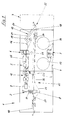
- a device 1 for folding and packaging hygiene products comprises a folding station 2, and an individual packaging device which, according to the exemplary embodiment, comprises a roll-off station 3 for film 4 for wrapping and individual packaging, a glue application and wrapping station 5 and a cross-embossing and cutting station 6 exists and which is finally followed by a packaging station 7.
- an individual packaging device which, according to the exemplary embodiment, comprises a roll-off station 3 for film 4 for wrapping and individual packaging, a glue application and wrapping station 5 and a cross-embossing and cutting station 6 exists and which is finally followed by a packaging station 7.
- another processing station could also be arranged behind the folding station 2.
- the folding station 2 expediently consists of two separate folding devices 8 and 9, so that the parts fed by a transport device 10 to the folding station 2 in the first folding device 8 are simple and then double-folded after further transport with the aid of the folding and transport belts 11 to the second folding device 9 can be.
- the parts reach the glue application and wrapping station 5 from the second folding device 9 with the aid of a transport device 12, in which they are individually packaged. This happens e.g. with the help of the film 4 or with the help of another material which is located on rollers 13 or 14 in the unwinding station 3.
- the arrangement of two rolls 13 and 14 enables a semiautomatic or fully automatic roll change in the unwinding station 3.
- the individually packaged parts then reach the cross-embossing and cutting station by means of a further transport device 15 and then by means of transport devices 16, 17 and 18 to the packaging station 7.
- the transport devices 16, 17 and 18 are expediently in each case around suction belts 20 driven by drive rollers 19, which run over suction boxes 21.
- the transport direction of the transport devices 16, 17 and 18 can therefore be arbitrary and in particular falling, as shown in FIG. 1.
- the transport device 16 initially transports the parts coming from the cross-stamping and cutting station 6 horizontally and then downwards.
- the transport device 17 takes over the parts from the transport device 16 and transports them over the approximately horizontally conveying transport device 18 and then delivers the parts to this transport device 18.
- a transport device 22 is also a bypass section to the folding station 2, to the glue application and wrapping station 5 and to the cross-embossing and cutting station 6 It is provided that the parts to be packaged can be transported directly and unfolded to the packing station 7 bypassing the folding station 2 and bypassing the individual packing station consisting of glue application and wrapping station 5 as well as cross-embossing and cutting station 6.
- This additional transport device 22 has at least one suction belt 23 and a drive roller 24 and at least one suction box 25. According to the embodiment shown in FIG. 1, three suction boxes 25, 26 and 27 are provided, over which a single suction belt 23 runs.
- the suction box 27 is expediently arranged in front of the first folding device 8 of the folding station 2 and directly behind the transport device 10 in the transport direction.
- the second suction box 26 of the transport device 22 in the transport direction extends from the first folding device 8 to the crossing point 28 with the film 4 used for wrapping during individual packaging.
- the third suction box 25 in the transport direction extends from the crossing point 28 to the transport device 18.
- no film 4 may be located in the area of the intersection 28 if the transport device 22 conveys individual parts directly from the transport device 10 to the transport device 18 with the aid of a suction belt 23 placed over the suction boxes 25 to 27. If the parts are to be folded one or more times and / or individually packed, it is necessary to remove the suction belt 23 so that the crossing point 28 is free for the film 4. Furthermore, a suction belt 29 a (Fig. 2) must be installed, which closes the transport gap between the transport device 10 and the folding station 2.
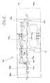
- FIG. 2 shows a modified embodiment, wherein the same parts have the same reference numerals with the letter index a.
- the device 1 according to FIG. 2 consists of the same stations as the device 1, it is only the suction belt 23 assigned to the long and several suction boxes 25, 26 and 27 by three suction belts 29a, 30 a and 31 a corresponding to the three suction boxes 25 a, 26a and 27 a replaced.
- the crossing point 28 a with the film 4 is therefore always free, because the suction belt 30 a has a deflection roller immediately in front of the crossing point 28 a and the same applies to the suction belt 31 a, which also has a deflection roller directly next to the crossing point 28 a.
- the suction belt 29 a can namely be effective both when the parts conveyed by the transport device 10 a are initially to be folded and / or individually packed, and also when the parts are to be packed unfolded.
- the transport device 18 or 18a together with the transport device 17, 17a also has the function of a collecting station or one Collective switch 32, 32a.
- the additional transport route serving as a bypass route is arranged in such a way that the parts transported further by it remain approximately in the same transport plane as in the region of the transport device 10 or 10a which conveys the parts to the folding station 2.
Landscapes
- Engineering & Computer Science (AREA)
- Mechanical Engineering (AREA)
- Auxiliary Devices For And Details Of Packaging Control (AREA)
- Basic Packing Technique (AREA)
- Wrapping Of Specific Fragile Articles (AREA)
Abstract
Description
- Die Erfindung betrifft eine Vorrichtung zum Falten und Verpacken von Hygieneprodukten, insbesondere von länglichen Teilen geringer Dicke, wobei die Vorrichtung mindestens eine Faltstation und gegebenenfalls weitere Stationen und schließlich eine Verpackungsstation umfasst. Bei den weiteren Stationen kann es sich z.B. um die verschiedenen Stationen einer Einzelverpackungseinrichtung handeln oder es ist hinter der Faltstation eine beliebige andere Bearbeitungsstation vorgesehen.
- Vorrichtungen der genannten Art sind bekannt und erfüllen die an sie gestellten Anforderungen grundsätzlich in zufriedenstellender Weise. In der hier vor allem interessierenden Vorrichtung werden die zu verpackenden Teile zunächst einfach oder mehrfach gefaltet und sodann einzelverpackt, woraufhin diese bereits einzelverpackten Teile nochmals in mehr oder weniger großen Gruppen mit frei wählbaren Stückzahlen, z.B. als Sechserpack oder als Zwölverpack verpackt werden.
- Der Erfindung liegt das Problem zugrunde, die Einsatzmöglichkeiten dieser Vorrichtung noch weiter zu erhöhen, so daß der Benutzer in der Lage ist, ein und dieselbe Vorrichtung für mindestens eine weitere Verpackungsart einzusetzen.
- Zur Lösung dieser Aufgabe sieht die Erfindung vor, daß zusätzlich eine Transporteinrichtung als Bypass-Strecke zur Faltstation und zu der/den nachgeschalteten Stationen derart vorgesehen ist, daß die zu verpackenden Teile unter Umgehung der Faltstation und der gegebenenfalls vorgesehenen, weiteren Stationen ungefaltet zur Verpakkungsstation transportierbar sind.
- Ein und dieselbe Produktionsmaschine kann sowohl zur Herstellung von ein- oder mehrfach gefalteten, z.B. einzelverpackten oder in sonstiger Weise bearbeiteten Teilen als auch zur Herstellung von ungefalteten, in Gruppen verpackten Teilen verwendet werden und besitzt daher einen gesteigerten Gebrauchswert. Es ist somit möglich, eine Einfach- bzw. Doppel-Faltstation mit gegebenenfalls integrierter Einzelverpackungseinrichtung und nachgeschalteter Mehrfachverpackungsstation auch unmittelbar als Mehrfach-Verpackungsstation einzusetzen, wenn dies gegebenenfalls erforderlich ist.
- Ferner ist in Weiterbildung der Erfindung vorgesehen, daß die als Bypass-Strecke dienende Transporteinrichtung auf dem Eingangsniveau zur Vorrichtung angeordnet ist. Hierdurch wird ein produktschonender, registergenauer Weitertransport der zu verpackenden Teile errreicht.
- Weitere Merkmale der Erfindung gehen aus Unteransprüchen im Zusammenhang mit der Beschreibung und der Zeichnung hervor.
- Die Erfindung wird nachstehend anhand von zwei Ausführungsbeispielen, die in der Zeichnung dargestellt sind, näher beschrieben. Dabei zeigen:
- Fig. 1 : in Seitenansicht eine Prinzipskizze der Vorrichtung und
- Fig. 2 : ebenfalls in Seitenansicht eine Prinzipskizze einer abgewandelten Ausführungsform.
- Eine Vorrichtung 1 zum Falten und Verpacken von Hygieneprodukten umfasst gemäß Fig. 1 eine Faltstation 2, und eine Einzelverpackungseinrichtung, die gemäß Ausführungsbeispiel aus einer Abrollstation 3 für Folie 4 zum Umhüllen und Einzelverpacken, einer Leimauftrag- und Umhüllstation 5 sowie einer Querpräge-und Schneidstation 6 besteht und an die sich schließlich noch eine Verpakkungsstation 7 anschließt. Anstelle der Einzelverpackungseinrichtung könnte auch eine andere Bearbeitungsstation hinter der Faltstation 2 angeordnet sein.
- Die Faltstation 2 besteht zweckmäßigerweise aus zwei gesonderten Falteinrichtungen 8 und 9, so daß die von einer Transporteinrichtung 10 der Faltstation 2 zugeführten Teile in der ersten Falteinrichtung 8 einfach und nach Weitertransport mit Hilfe der Falt- und Transportbändern 11 zur zweiten Falteinrichtung 9 sodann dort doppelt gefaltet werden können. Von der zweiten Falteinrichtung 9 gelangen die Teile mit Hilfe einer Transporteinrichtung 12 zur Leimauftrags- und Umhüllstation 5, in der sie einzelverpackt werden. Dies geschieht z.B. mit Hilfe der Folie 4 oder mit Hilfe eines anderen Werkstoffes, der sich auf Rollen 13 bzw. 14 in der Abrollstation 3 befindet. Die Anordnung von zwei Rollen 13 bzw. 14 ermöglicht einen halb- bzw. vollautomatischn Rollenwechsel in der Abrollstation 3.
- Von der Leimauftrags- und Umhüllstation 5 gelangen die einzelverpackten Teile sodann mit Hilfe einer weiteren Transporteinrichtung 15 zur Querpräge- und Schneidstation und sodann mit Hilfe von Transporteinrichtungen 16, 17 und 18 zur Verpackungsstation 7. Bei den Transporteinrichtungen 16, 17 und 18 handelt es sich zweckmäßigerweise jeweils um von Antriebsrollen 19 angetriebene Sauggurte 20, die über Saugkästen 21 laufen. Die Transportrichtung der Transporteinrichtungen 16, 17 und 18 kann daher beliebig und insbesondere auch fallend sein, wie dies in Fig. 1 dargestellt ist. So transportiert die Transporteinrichtung 16 die aus der Querpräge-und Schneidstation 6 kommenden Teile zunächst horizontal weiter und sodann abwärts. Bei dem abwärts gerichteten Transport übernimmt die Transporteinrichtung 17 die Teile von der Transporteinrichtung 16 und transportiert sie bis über die annähernd horizontal fördernde ransporteinrichtung 18 und gibt die Teile sodann an diese Transporteinrichtung 18 ab.
- Wie Fig. 1 ferner zeigt, ist zusätzlich noch eine Transporteinrichtung 22 als Bypass-Strecke zur Faltstation 2, zur Leimauftrag-und Umhüllstation 5 sowie zur Querpräge-und Schneistation 6 derart vorgesehen, daß die zu verpackenden Teile unter Umgehung der Faltstation 2 und unter Umgehung der aus Leimauftrag- und Umhüllstation 5 sowie Querpräge- und Schneidstation 6 bestehenden Einzelver- packstation unmittelbar und ungefaltet zur Verpackungsstation 7 transportierbar sind. Diese zusätzliche Transporteinrichtung 22 weist mindestens einen Sauggurt 23 und eine Antriebsrolle 24 sowie mindestens einen Saugkasten 25 auf. Gemäß dem in Fig. 1 dargestellten Ausführungsbeispiel sind drei Saugkästen 25, 26 und 27 vorgesehen, über die ein einziger Sauggurt 23 läuft. Der Saugkasten 27 ist dabei zweckmäßigerweise vor der ersten Falteinrichtung 8 der Faltstation 2 sowie unmittelbar in Transportrichtung hinter der Transporteinrichtung 10 angeordnet. Der in Transportrichtung zweite Saugkasten 26 der Transporteinrichtung 22 erstreckt sich von der ersten Falteinrichtung 8 bis zur Kreuzungsstelle 28 mit der zum Umhüllen beim Einzelverpacken dienenden Folie 4. Der in Transportrichtung dritte Saugkasten 25 reicht von der Kreuzungsstelle 28 bis zur Transporteinrichtung 18.
- Es versteht sich, daß sich keine Folie 4 im Bereich der Kreuzungsstelle 28 befinden darf, wenn die Transporteinrichtung 22 mit Hilfe eines über die Saugkästen 25 bis 27 gelegten Sauggurtes 23 Einzelteile unmittelbar von der Transporteinrichtung 10 zur Transporteinrichtung 18 fördert. Wenn die Teile ein- oder mehrfach gefaltet und / oder einzelverpackt werden sollen, so ist es erforderlich, den Sauggurt 23 abzunehmen, damit die Kreuzungsstelle 28 für die Folie 4 frei ist. Ferner muß ein Sauggurt 29 a (Fig. 2) eingebaut werden, der die Transportlücke zwischen der Transporteinrichtung 10 und der Faltstation 2 schließt.
- Fig. 2 zeigt ein abgewandeltes Ausführungsbeispiel, wobei gleiche Teile dieselben Bezugszahlen mit dem Buchstabenindex a tragen. Die Vorrichtung 1 gemäß Fig. 2 besteht aus denselben Stationen wie die Vorrichtung 1, es ist lediglich der langen und mehreren Saugkästen 25, 26 und 27 zugeordnete Sauggurt 23 durch drei Sauggurte 29a, 30 a und 31 a entsprechend den drei Saugkästen 25 a, 26a und 27 a ersetzt. Die Kreuzungsstelle 28 a mit der Folie 4 ist dadurch immer frei, denn der Sauggurt 30 a weist eine Umlenkrolle unmittelbar vor der Kreuzungsstelle 28a auf und Gleiches gilt für den Sauggurt 31 a, der ebenfalls eine Umlenkrolle unmittelbar neben der Kreuzungsstelle 28 a aufweist. Auch der Saugkasten 27 a ist bei der Ausführungsform gemäß Fig. 2 immer mit ein und demselben Sauggurt 29 a versehen, so daß auch hier Umbaumaßnahmen bei einer Änderung der Betriebsart nicht erforderlich sind. Der Sauggurt 29 a kann nämlich sowohl dann wirksam sein, wenn die von der Transporteinrichtung 10 a geförderten Teile zunächst gefaltet und/ oder einzelverpackt werden sollen als auch dann, wenn die Teile ungefaltet zu verpacken sind.
- Da sowohl die Transporteinrichtung 17 bzw. 17 a als auch die Transporteinrichtung 22 bzw. 31 a die Teile jeweils zur Transporteinrichtung 18, 18a fördern, hat die Transporteinrichtung 18 bzw. 18a zusammen mit der Transporteinrichtung 17, 17a auch die Funktion einer Sammelstation bzw. einer Sammelweiche 32, 32a.
- Grundsätzlich ist es ferner möglich, die Transporteinrichtungen mit Sauggurten durch Transporteinrichtungen mit Ober- und Untergurt bzw. durch Greifertransporteinrichtungen zu ersetzen.
- Schließlich ist es vorteilhaft, wenn die als Bypass-Strecke dienende, zusätzliche Transportstrecke derart angeordnet ist, daß die von ihr weitertransportierten Teile etwa in der gleichen Transportebene verbleiben wie im Bereich der die Teile zur Faltstation 2 fördernden Transporteinrichtung 10 bzw. 10a.
Claims (10)
Applications Claiming Priority (2)
| Application Number | Priority Date | Filing Date | Title |
|---|---|---|---|
| DE4141143A DE4141143A1 (de) | 1991-12-13 | 1991-12-13 | Vorrichtung zum falten und verpacken von hygieneprodukten |
| DE4141143 | 1991-12-13 |
Publications (2)
| Publication Number | Publication Date |
|---|---|
| EP0546433A1 true EP0546433A1 (de) | 1993-06-16 |
| EP0546433B1 EP0546433B1 (de) | 1995-10-25 |
Family
ID=6446981
Family Applications (1)
| Application Number | Title | Priority Date | Filing Date |
|---|---|---|---|
| EP92120528A Expired - Lifetime EP0546433B1 (de) | 1991-12-13 | 1992-12-02 | Vorrichtung zum Falten und Verpacken von Hygieneprodukten |
Country Status (4)
| Country | Link |
|---|---|
| US (1) | US5373680A (de) |
| EP (1) | EP0546433B1 (de) |
| JP (1) | JP3490105B2 (de) |
| DE (2) | DE4141143A1 (de) |
Cited By (2)
| Publication number | Priority date | Publication date | Assignee | Title |
|---|---|---|---|---|
| EP0608906A3 (en) * | 1994-02-07 | 1994-09-14 | Krempel August Soehne | Apparatus and method for treating hosiery articles. |
| CN119190934A (zh) * | 2024-11-27 | 2024-12-27 | 福建培新机械制造实业有限公司 | 一种护垫生产线 |
Families Citing this family (2)
| Publication number | Priority date | Publication date | Assignee | Title |
|---|---|---|---|---|
| EP1048369A1 (de) * | 1999-03-22 | 2000-11-02 | Boegli-Gravures S.A. | Prägevorrichtung für flächenhaft ausgedehntes Material |
| GB201512819D0 (en) * | 2015-07-21 | 2015-09-02 | Scaife Martin | Customised fast moving consumer goods production system |
Citations (5)
| Publication number | Priority date | Publication date | Assignee | Title |
|---|---|---|---|---|
| US2815949A (en) * | 1955-02-01 | 1957-12-10 | Time Inc | Apparatus for receiving printed material |
| US3859898A (en) * | 1971-11-12 | 1975-01-14 | Fmc Corp | Method of and apparatus for stacking flexible articles |
| EP0004379A1 (de) * | 1978-03-25 | 1979-10-03 | August Krempel Söhne GmbH & Co. | Faltmaschine für biegeschlaffe Erzeugnisse, insbesondere Textilien |
| EP0121432A2 (de) * | 1983-03-31 | 1984-10-10 | Chambon Limited | Leitvorrichtung in einer Einrichtung zum Ausgeben von Pappbögen |
| DE3431548A1 (de) * | 1984-08-28 | 1986-03-13 | Winkler & Dünnebier, Maschinenfabrik und Eisengießerei GmbH & Co KG, 5450 Neuwied | Verfahren und vorrichtung zur einzelverpackung von hygieneartikeln |
Family Cites Families (17)
| Publication number | Priority date | Publication date | Assignee | Title |
|---|---|---|---|---|
| US1987211A (en) * | 1931-01-21 | 1935-01-08 | Stokes & Smith Co | Method of towel folding and wrapping |
| US3286435A (en) * | 1963-07-24 | 1966-11-22 | Holland Rantos Company Inc | Moist packaged article and method of making same |
| US3500611A (en) * | 1966-08-26 | 1970-03-17 | Holland Rantos Co Inc | Moist packaged article and equipment for making same |
| DK117478B (da) * | 1968-10-15 | 1970-04-27 | Skandinavisk Emballage | Vigespor til en produktionslinie med efter hinanden følgende transportører. |
| BE789625A (fr) * | 1971-11-12 | 1973-02-01 | Fmc Corp | Procede et appareil pour emballer des articles flexibles |
| US3973373A (en) * | 1975-03-10 | 1976-08-10 | Colgate-Palmolive Company | Automatic packaging method and apparatus |
| DE2702339A1 (de) * | 1977-01-21 | 1978-07-27 | Bikoma Gmbh | Verfahren und vorrichtung zur uebergabe von sanitaeren einlagen von einer fertigungsvorrichtung an eine verpackungsvorrichtung |
| CH621305A5 (de) * | 1978-06-05 | 1981-01-30 | Sapal Plieuses Automatiques | |
| GB2029353B (en) * | 1978-09-06 | 1982-08-11 | Baker Perkins Holdings Ltd | Apparatus for feeding articles to pakaging machines |
| CH655286A5 (de) * | 1982-05-03 | 1986-04-15 | Sig Schweiz Industrieges | Vorrichtung zum wahlweisen umlenken von gegenstaenden auf eines von zwei foerderbaendern, verfahren zu ihrem betrieb und verwendung. |
| DE3227950A1 (de) * | 1982-07-27 | 1984-03-01 | Carlo 6500 Mainz Schaberger | Stetigfoerderer fuer konische hohlglaeser |
| GB2128953B (en) * | 1982-10-28 | 1986-04-09 | Bishopbarn Ltd | Conveyor with suction means for holding articles in contact therewith |
| DE3527712A1 (de) * | 1985-08-02 | 1987-02-12 | Roland Man Druckmasch | Falzapparat mit einer sammelvorrichtung vor dem dritten falz |
| DE3527710A1 (de) * | 1985-08-02 | 1987-02-12 | Roland Man Druckmasch | Falzapparat zum querfalzen zugeschnittener druckexemplare |
| DE3617259A1 (de) * | 1986-05-22 | 1987-11-26 | Haensel Otto Gmbh | Verfahren und vorrichtung zur uebergabe von packstuecken wie beutel, blister oder dgl. von einer verpackungsmaschine in eine kartoniermaschine |
| DE4028889A1 (de) * | 1990-09-12 | 1992-03-19 | Winkler Duennebier Kg Masch | Verfahren und vorrichtung zum falten von hygieneprodukten |
| US5113639A (en) * | 1991-02-19 | 1992-05-19 | Am International Incorporated | Selective article wrapping |
-
1991
- 1991-12-13 DE DE4141143A patent/DE4141143A1/de not_active Withdrawn
-
1992
- 1992-12-02 DE DE59204132T patent/DE59204132D1/de not_active Expired - Lifetime
- 1992-12-02 EP EP92120528A patent/EP0546433B1/de not_active Expired - Lifetime
- 1992-12-11 JP JP35330192A patent/JP3490105B2/ja not_active Expired - Fee Related
- 1992-12-11 US US07/989,070 patent/US5373680A/en not_active Expired - Fee Related
Patent Citations (5)
| Publication number | Priority date | Publication date | Assignee | Title |
|---|---|---|---|---|
| US2815949A (en) * | 1955-02-01 | 1957-12-10 | Time Inc | Apparatus for receiving printed material |
| US3859898A (en) * | 1971-11-12 | 1975-01-14 | Fmc Corp | Method of and apparatus for stacking flexible articles |
| EP0004379A1 (de) * | 1978-03-25 | 1979-10-03 | August Krempel Söhne GmbH & Co. | Faltmaschine für biegeschlaffe Erzeugnisse, insbesondere Textilien |
| EP0121432A2 (de) * | 1983-03-31 | 1984-10-10 | Chambon Limited | Leitvorrichtung in einer Einrichtung zum Ausgeben von Pappbögen |
| DE3431548A1 (de) * | 1984-08-28 | 1986-03-13 | Winkler & Dünnebier, Maschinenfabrik und Eisengießerei GmbH & Co KG, 5450 Neuwied | Verfahren und vorrichtung zur einzelverpackung von hygieneartikeln |
Cited By (2)
| Publication number | Priority date | Publication date | Assignee | Title |
|---|---|---|---|---|
| EP0608906A3 (en) * | 1994-02-07 | 1994-09-14 | Krempel August Soehne | Apparatus and method for treating hosiery articles. |
| CN119190934A (zh) * | 2024-11-27 | 2024-12-27 | 福建培新机械制造实业有限公司 | 一种护垫生产线 |
Also Published As
| Publication number | Publication date |
|---|---|
| US5373680A (en) | 1994-12-20 |
| DE59204132D1 (de) | 1995-11-30 |
| EP0546433B1 (de) | 1995-10-25 |
| DE4141143A1 (de) | 1993-06-17 |
| JP3490105B2 (ja) | 2004-01-26 |
| JPH05270511A (ja) | 1993-10-19 |
Similar Documents
| Publication | Publication Date | Title |
|---|---|---|
| EP0096223B1 (de) | Trenneinrichtung zum Abtrennen perforierter Papierschlauchabschnitte | |
| EP0986478B1 (de) | Verfahren zum Einziehen einer Teilpapierbahn | |
| EP0031515B1 (de) | Vorrichtung zum Herstellen von Packungs-Zuschnitten durch Abtrennen von einer fortlaufenden Bahn | |
| EP0498068B1 (de) | Falzapparat, bei dem der Transport der Falzexemplare über Transportmittel, Bandrollen und Bänder erfolgt | |
| EP0481172B1 (de) | Rollenrotationsdruckmaschine für Bücher- und Kalenderdruck mit zwei Längsfalzvorrichtungen | |
| EP1120238A2 (de) | Verfahren und Vorrichtung zur Zuführung einer Materialbahn bei der herstellung von Packungen | |
| EP0752383B1 (de) | Vorrichtung zum Vereinzeln gestapelter flacher Gegenstände | |
| DE2823247C2 (de) | Einrichtung zur Umlenkung eines aus bogenförmigen Produkten bestehenden Produktstroms | |
| DE3315490A1 (de) | Verfahren und vorrichtung zum stapeln von druckbogen o.dgl. | |
| DE3524246A1 (de) | Verfahren und vorrichtung zum zick-zack-falten endloser materialbahnen | |
| DE2657789A1 (de) | Einrichtung zum einziehen einer papierbahn in den falzapparat einer rotationsdruckmaschine | |
| EP0371219B1 (de) | Einrichtung zum Stapeln von kontinuierlich anfallenden, im wesentlichen viereckigen Druckereiprodukten | |
| WO1999062700A1 (de) | Faltschachtelklebemaschine zur herstellung von faltschachteln aus zuschnitten | |
| EP0623458A2 (de) | Verfahren und Vorrichtung zum Beleimen von Papier- und/oder Kunststoff- bzw. Mischprodukten mit einem Haftklebemittel | |
| DE2723358C2 (de) | Falzapparat für Buchfalzungen an Rollenrotationsdruckmaschinen | |
| DE69504244T2 (de) | Verfahren zum gegenseitigen Repositionieren von Produkten, zum Beispiel zum Einstellen von der gegenseitigen Position von graphischen Produkten in einer Verpackungsvorrichtung, und eine Zufuhrvorrichtung zum Ausführen des Verfahren | |
| EP2409938A2 (de) | Unterdruckfördereinrichtung | |
| DE2612945A1 (de) | Vorrichtung zum falten der vorderen und hinteren waende einer faltschachtel | |
| EP0546433B1 (de) | Vorrichtung zum Falten und Verpacken von Hygieneprodukten | |
| EP0415904B1 (de) | Vorrichtung zum Aufteilen eines Schuppenstromes aus jeweils übereinanderliegenden Nutzen | |
| WO2022012881A1 (de) | Falzmaschine mit einem schwertfalzwerk und verfahren zum falzen von falzprodukten mittels eines schwertfalzwerks | |
| EP0722518B1 (de) | Verfahren und vorrichtung zum säumen von textilen bahnen | |
| EP1025993A2 (de) | Vorrichtung zum Auftragen einer Längsleimung in einer Falzvorrichtung von schnellaufenden Rotationsdruckmaschinen | |
| DE4038457C2 (de) | Arbeitsverfahren und Vorrichtung zum Entmanteln von in einstückigen Faltkartons verpackten tiefgefrorenen Blöcken in flacher Quaderform | |
| EP0705766B1 (de) | Verfahren zur Herstellung eines Verpackungsbeutels aus Papier, Kunststoff od.dgl. |
Legal Events
| Date | Code | Title | Description |
|---|---|---|---|
| PUAI | Public reference made under article 153(3) epc to a published international application that has entered the european phase |
Free format text: ORIGINAL CODE: 0009012 |
|
| AK | Designated contracting states |
Kind code of ref document: A1 Designated state(s): CH DE FR GB IT LI SE |
|
| 17P | Request for examination filed |
Effective date: 19930726 |
|
| 17Q | First examination report despatched |
Effective date: 19940725 |
|
| GRAA | (expected) grant |
Free format text: ORIGINAL CODE: 0009210 |
|
| AK | Designated contracting states |
Kind code of ref document: B1 Designated state(s): CH DE FR GB IT LI SE |
|
| REF | Corresponds to: |
Ref document number: 59204132 Country of ref document: DE Date of ref document: 19951130 |
|
| ET | Fr: translation filed | ||
| GBT | Gb: translation of ep patent filed (gb section 77(6)(a)/1977) |
Effective date: 19951130 |
|
| REG | Reference to a national code |
Ref country code: CH Ref legal event code: NV Representative=s name: ISLER & PEDRAZZINI AG PATENTANWAELTE |
|
| ITF | It: translation for a ep patent filed | ||
| PLBE | No opposition filed within time limit |
Free format text: ORIGINAL CODE: 0009261 |
|
| STAA | Information on the status of an ep patent application or granted ep patent |
Free format text: STATUS: NO OPPOSITION FILED WITHIN TIME LIMIT |
|
| 26N | No opposition filed | ||
| PGFP | Annual fee paid to national office [announced via postgrant information from national office to epo] |
Ref country code: CH Payment date: 19961129 Year of fee payment: 5 |
|
| PG25 | Lapsed in a contracting state [announced via postgrant information from national office to epo] |
Ref country code: LI Free format text: LAPSE BECAUSE OF NON-PAYMENT OF DUE FEES Effective date: 19971231 Ref country code: CH Free format text: LAPSE BECAUSE OF NON-PAYMENT OF DUE FEES Effective date: 19971231 |
|
| REG | Reference to a national code |
Ref country code: CH Ref legal event code: PL |
|
| PGFP | Annual fee paid to national office [announced via postgrant information from national office to epo] |
Ref country code: GB Payment date: 20001204 Year of fee payment: 9 Ref country code: SE Payment date: 20001204 Year of fee payment: 9 |
|
| PGFP | Annual fee paid to national office [announced via postgrant information from national office to epo] |
Ref country code: FR Payment date: 20001227 Year of fee payment: 9 |
|
| PG25 | Lapsed in a contracting state [announced via postgrant information from national office to epo] |
Ref country code: GB Free format text: LAPSE BECAUSE OF NON-PAYMENT OF DUE FEES Effective date: 20011202 |
|
| PG25 | Lapsed in a contracting state [announced via postgrant information from national office to epo] |
Ref country code: SE Free format text: LAPSE BECAUSE OF NON-PAYMENT OF DUE FEES Effective date: 20011203 |
|
| REG | Reference to a national code |
Ref country code: GB Ref legal event code: IF02 |
|
| GBPC | Gb: european patent ceased through non-payment of renewal fee |
Effective date: 20011202 |
|
| EUG | Se: european patent has lapsed |
Ref document number: 92120528.2 |
|
| PG25 | Lapsed in a contracting state [announced via postgrant information from national office to epo] |
Ref country code: FR Free format text: LAPSE BECAUSE OF NON-PAYMENT OF DUE FEES Effective date: 20020830 |
|
| REG | Reference to a national code |
Ref country code: FR Ref legal event code: ST |
|
| PGFP | Annual fee paid to national office [announced via postgrant information from national office to epo] |
Ref country code: IT Payment date: 20091223 Year of fee payment: 18 |
|
| PGFP | Annual fee paid to national office [announced via postgrant information from national office to epo] |
Ref country code: DE Payment date: 20100222 Year of fee payment: 18 |
|
| REG | Reference to a national code |
Ref country code: DE Ref legal event code: R119 Ref document number: 59204132 Country of ref document: DE Effective date: 20110701 |
|
| PG25 | Lapsed in a contracting state [announced via postgrant information from national office to epo] |
Ref country code: DE Free format text: LAPSE BECAUSE OF NON-PAYMENT OF DUE FEES Effective date: 20110701 |
|
| PG25 | Lapsed in a contracting state [announced via postgrant information from national office to epo] |
Ref country code: IT Free format text: LAPSE BECAUSE OF NON-PAYMENT OF DUE FEES Effective date: 20101202 |