EP0121432A2 - Leitvorrichtung in einer Einrichtung zum Ausgeben von Pappbögen - Google Patents
Leitvorrichtung in einer Einrichtung zum Ausgeben von Pappbögen Download PDFInfo
- Publication number
- EP0121432A2 EP0121432A2 EP84302223A EP84302223A EP0121432A2 EP 0121432 A2 EP0121432 A2 EP 0121432A2 EP 84302223 A EP84302223 A EP 84302223A EP 84302223 A EP84302223 A EP 84302223A EP 0121432 A2 EP0121432 A2 EP 0121432A2
- Authority
- EP
- European Patent Office
- Prior art keywords
- blanks
- suction
- guide apparatus
- belts
- conveyor means
- Prior art date
- Legal status (The legal status is an assumption and is not a legal conclusion. Google has not performed a legal analysis and makes no representation as to the accuracy of the status listed.)
- Granted
Links
Images


Classifications
-
- D—TEXTILES; PAPER
- D21—PAPER-MAKING; PRODUCTION OF CELLULOSE
- D21C—PRODUCTION OF CELLULOSE BY REMOVING NON-CELLULOSE SUBSTANCES FROM CELLULOSE-CONTAINING MATERIALS; REGENERATION OF PULPING LIQUORS; APPARATUS THEREFOR
- D21C1/00—Pretreatment of the finely-divided materials before digesting
-
- B—PERFORMING OPERATIONS; TRANSPORTING
- B65—CONVEYING; PACKING; STORING; HANDLING THIN OR FILAMENTARY MATERIAL
- B65H—HANDLING THIN OR FILAMENTARY MATERIAL, e.g. SHEETS, WEBS, CABLES
- B65H29/00—Delivering or advancing articles from machines; Advancing articles to or into piles
- B65H29/24—Delivering or advancing articles from machines; Advancing articles to or into piles by air blast or suction apparatus
- B65H29/241—Suction devices
- B65H29/242—Suction bands or belts
-
- B—PERFORMING OPERATIONS; TRANSPORTING
- B65—CONVEYING; PACKING; STORING; HANDLING THIN OR FILAMENTARY MATERIAL
- B65H—HANDLING THIN OR FILAMENTARY MATERIAL, e.g. SHEETS, WEBS, CABLES
- B65H29/00—Delivering or advancing articles from machines; Advancing articles to or into piles
- B65H29/58—Article switches or diverters
- B65H29/60—Article switches or diverters diverting the stream into alternative paths
-
- B—PERFORMING OPERATIONS; TRANSPORTING
- B65—CONVEYING; PACKING; STORING; HANDLING THIN OR FILAMENTARY MATERIAL
- B65H—HANDLING THIN OR FILAMENTARY MATERIAL, e.g. SHEETS, WEBS, CABLES
- B65H2406/00—Means using fluid
- B65H2406/30—Suction means
- B65H2406/32—Suction belts
- B65H2406/323—Overhead suction belt, i.e. holding material against gravity
-
- B—PERFORMING OPERATIONS; TRANSPORTING
- B65—CONVEYING; PACKING; STORING; HANDLING THIN OR FILAMENTARY MATERIAL
- B65H—HANDLING THIN OR FILAMENTARY MATERIAL, e.g. SHEETS, WEBS, CABLES
- B65H2701/00—Handled material; Storage means
- B65H2701/10—Handled articles or webs
- B65H2701/17—Nature of material
- B65H2701/176—Cardboard
Definitions
- This invention relates to guide apparatus tor a carton blank delivery system, to a carton blank delivery system incorporating such a guide apparatus, and to a method of guiding and separating blanks from a stream or a plurality of rows of blanks.
- the guide apparatus of the invention is intended particularly to guide some of the blanks of a stream of a plurality of rows or blanks in a first direction, and to guide the rest of said blanks in a second direction, thereby separating the stream of blanks into two streams.
- Guide apparatus of this type is necessary in blank delivery systems when either the speed of the input stream of blanks is so high that inteference occurs between successive blanks as they are ejected onto a shingling conveyor (that is to say the tail of one blank has insufficient time to fall clear of the leading edge of the following blank); or the blanks are nested, rotated or printed in such a manner that they must be collected separately.
- the aim of the invention is to provide guide apparatus which can be used tc separate blanks, and which is reliable in opeiation, and is easily modified to accommoaate different sizes and shapes of blank.
- the apparatus comprising first and second conveyor means wnose input ends are positionea on opposite sides of the feed path of a stream of a plurality of rows of blanks to the apparatus, wherein each of the conveyor means is constituted by a plurality of laterally-spaced suction belt means, each suction belt means being aligned with the feed path of a respective row of blanks, the conveyor means being such that some ot the blanks are conveyed by the suction belt means of the first conveyor means and the rest of the blanks are conveyed by the suction belt means of the second conveyor means.
- the conveyor means are such that alternate blanks of each row are conveyed by the suction belt means of the first and second conveyor means.
- first and second conveyor means diverge away from the input ends thereof and in the direction of blank feed.
- each of the suction belt means is constituted by a pair of suction belts which are laterally spaced with respect to the direction of blank feed.
- each of the conveyor means is constituted by three pairs of laterally-spaced suction belts.
- each of the suction belts is provided with a plurality of suction ports.
- the suction belts of the two sets of conveyor means may be driven in synchronism, and the suction ports of said suction belts may be so positioned that some ot the blanks of each row of blanks are picked up by the suction ports of the suction belts of the first conveyor means, and the rest of the blanks of each row of blanks are picked up by the suction ports ot the suction belts of the second conveyor means.
- each suction belt may have an even number of sets of suction ports.
- Each set of suction ports may have at least one, and preferably two, suction ports.
- suction ports may be positioned in a continuous row round each of the suction belts.
- means may be provided for closing at least one suction port of at least one suction belt, and the suction ports of each suction belt are equispaced.
- a respective box-like chamber is associated with each of the suction belts, the portion of each chamber which faces the associated suction belt being closed off by a curved, longitudinally-slotted plate, and the chambers being connectible to a vacuum pump via an inlet manifold, the arrangement being such that each of the suction belts passes over the associated curved, longitudinally-slotted plate so that the suction ports of the belts can be subjected to a sub-atmospheric pressure.
- the present invention also provides a system for delivery blanks, the system comprising feed means for receiving a stream of a plurality of rows of blanks from an upstream processing unit, guide apparatus positioned downstream or the feed means, and first and second pairs of shingling units positioned downstream of the guide apparatus, the guide apparatus being as defined above, wherein respective shingling units of the first pair of shingling units are positioned at the downstream ends of the first and second conveyor means, and respective shingling units of the second pair of shingling units are positioned at the downstream ends of the shingling units of the first pair.
- the invention further provides a method of guiding and separating blanks, the method comprising the steps of guiding some blanks of a continuous stream of a plurality of rows of blanks in a first direction by means of a plurality of laterally-spaced suction belt means, and of guiding the rest of said blanks in a second direction using a plurality of laterally-spaced further suction belt means.
- Fig. 1 shows a delivery system which comprises feed means A, guide means B positioned downstream of the feed means, a first pair of shingling units C l and C 2 positioned downstream of the guide apparatus, and a second pair of shingling units D 1 and D 2 positioned downstream of the first pair of shingling units.
- the feed means A is arranged to deliver a continuous stream of carton blanks 1 to the guide apparatus, and is constituted by a plurality of pairs of rollers 2.
- the feed means A is positioned downstream of cutting and creasing units (not shown) which are effective to cut out and crease carton blanks from a continuous web of board.
- the pre-formed carton blanks 1 are fed to the guide apparatus in three rows. Moreover, alternate blanks of each row are "right-hand" blanks la and "left-hand” blanks lb.
- the right-hand blanks la are identical with the left-hand blanks lb, but are rotated through 180° with respect to the left-hand blanks.
- the blanks 1 are formed in this manner, with right-hand blanks la alternating with left-hand blanks lb, as this results in a smaller amount of scrap material than would be the case if all the blanks were pre-formed as either right-hand blanks or left-hand blanKs.
- the guide apparatus B is constituted by an upper set of conveyors E, and a lower set of conveyors F, (see Fig. 2). There are six conveyors in each of the sets E and F, and the guide apparatus is arranged so that two conveyors of each set are aligned with the lateral edge portions of the blanks 1 in each of the three rows of blanks. As shown best in Fig. 1, the two sets of conveyors E and F diverge in the direction of carton blank feed.
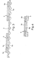
- Each conveyor E or F includes an endless, internally-toothed belt 3 (best seen in Fig. 3), which is driven by a pair of externally-toothed wheels 4 and 5.
- a respective box-like chamber 6 is associated with each of the belts 3.
- the inwardly-facing surfaces of the chambers 6 are closed off by curvec, longitudinally-slotted plates (not shown).
- the conveyors E and F are so constructed that each of the belts 3 passes over the curved, slotted plate of the associated chamber 6.
- Each of the chambers 6 is connected to a vacuum pump (not shown) via an inlet manifold 7 and a pair of inlets 8.
- Each of the belts 3 is provided with four sets ot suction ports 9.
- the sets of suction ports 9 are equispaced around the belts 3, and each of these sets has two suction ports.
- Each of the ports 9 is constituted by an aperture 9a in the associated belt 3, and by a washer-shaped head 9b fixed to the outer surface of the belt.
- the suction ports 9 are subjected to the partial vacuum within these chambers, so that any blank 1 in contact therewith will be held iirmly against tne associated belt.
- Each of the ports 9 can be sealed oft from the partial vacuum inside the associated chamber 6 by means of a respective disc 9c which is a snap fit within the head of that port (see Figs. 3 and 4).
- the belts 3 can easily be adapted to vary the number of ports 9 in use.
- the belts 3 are driven in synchronism by a common drive means (not shown) via gear means (not shown).
- the suction ports 9 are so positioned on their belts that, as the rows of blanks 1 are fed to the input end of the guide apparatus B, alternate blanks of each row are pickea up by the belts 3 of the conveyors E, and alternate blanks are picked up by the belts 3 of the conveyors F.
- the right-hand blanks la can be picked up by the belts 3 of the upper conveyors E and the left-hand blanks lb can be picked up by the belts 3 of the lower conveyors F.
- the right-hand blanks la are separated from the left-hand blanks lb, so that there is no danger of interference between successive blanks as they are fed along the delivery system downstream of the guide apparatus B.
- the shingling units C 1 and C 2 are standard conveyor-belt shingling units whose speed is slightly less than half that of the input speed of the carton blanks la and lb. Thus, the shingling units C 1 and C 2 are effective to overlap the leading and trailing edges of the carton blanks la and lb by a small amount.
- the carton blanks la and lb pass respectively to second shingling units D 1 and D 2 .
- the shingling units D 1 and D 2 are also standard conveyor-belt shingling units.
- the units D 1 and D 2 are slow-speed shingling units, and the carton blanks la and lb are made to over lap by almost their full length in these units.
- the two sets of shingling units C and D are, therefore, effective to slow down the delivery speed of the carton blanks la and lb, and to perform a preliminary stacking operation.
- As the blanks leave the downstream shingling units D 1 and D 2 they are, therefore, ready for immediate stacking by either manual or automatic means.
- the guide apparatus described above has a number of advantages.
- this apparatus is particularly suitable for separating successive blanks which are nested, positioned or printed in such a manner that they must be collected separately.
- Another advantage of this guide apparatus is that the use of suction belts is effective to guide the blanks through the entire length of the guide apparatus, and this was not possible with the known types of apparatus using deflector plates or oscillating rollers. Consequently, this guide apparatus gives an improved guiding function.
- the blanks are held in position by suction belts at their opposite lateral edges as they pass through the apparatus, so that this guiding function is particularly positive and secure.
- each of the suction belts 3 could be provided with a different number of sets of suction ports 9.
- each suction belt 3 could have any number of sets of suction ports 9, but two, four, six or any other even number of sets of suction ports is preferred.
- each set of suction ports 9 could comprise one or more suction ports.
- each suction belt 3 could be provided with a continuous row of equispaced suction ports 9. In use, and depending upon the particular configuration of the blanks to be guided, most of the suction ports 9 would be blocked off by discs 9c, so that only the suction ports positioned at predetermined spacings along the suction belts 3 would be used to convey the blanks.
- this particular arrangement is very versatile, as it enables the same suction belts 3 to be used for conveying many different types of blank, it being necessary only to block off different suction ports 9 for each type of blank.
- the guide apparatus described above could also be used to separate some blanks of a continuous stream of a plurality of rows of blanks from the rest thereof.
- the guide apparatus is used downstream of a printing and processing init which utilises a printing roller which has three circumferentially-spaced dies in each row of several transversely-spaced rows, one die of each row may be arranged to print a different blank from the other two dies of that row.
- the suction belts 3 of the conveyors of one of the sets E or F will be arranged to convey every third blank, and the suction belts 3 of the conveyors of the other set will be arranged to guide the rest of the blanks. In this way, different blanks can be separated from the continuous stream containing both types of blank in a reliable manner.
- the apparatus described above could also be used to separate all the blanks in a given row from all the blanks in an adjacent row.
- the blanks of a plurality of rows of blanks can be separated transversely as well as longitudinally. This is particularly useful for blanks which are excessively interleafed edge-to-edge.
- suction belt means usually a plurality of pairs of suction belts
- each conveyor will diverge transversely (as well as vertically) with respect to the direction of feed.
Landscapes
- Engineering & Computer Science (AREA)
- Mechanical Engineering (AREA)
- Auxiliary Devices For And Details Of Packaging Control (AREA)
- Making Paper Articles (AREA)
- Supplying Of Containers To The Packaging Station (AREA)
- Delivering By Means Of Belts And Rollers (AREA)
- Sheets, Magazines, And Separation Thereof (AREA)
- Paper (AREA)
- Photographic Developing Apparatuses (AREA)
- Branching, Merging, And Special Transfer Between Conveyors (AREA)
Priority Applications (1)
| Application Number | Priority Date | Filing Date | Title |
|---|---|---|---|
| AT84302223T ATE31284T1 (de) | 1983-03-31 | 1984-03-30 | Leitvorrichtung in einer einrichtung zum ausgeben von pappboegen. |
Applications Claiming Priority (2)
| Application Number | Priority Date | Filing Date | Title |
|---|---|---|---|
| GB8309038 | 1983-03-31 | ||
| GB838309038A GB8309038D0 (en) | 1983-03-31 | 1983-03-31 | Guide apparatus for carton blank delivery system |
Publications (3)
| Publication Number | Publication Date |
|---|---|
| EP0121432A2 true EP0121432A2 (de) | 1984-10-10 |
| EP0121432A3 EP0121432A3 (en) | 1986-01-22 |
| EP0121432B1 EP0121432B1 (de) | 1987-12-09 |
Family
ID=10540583
Family Applications (1)
| Application Number | Title | Priority Date | Filing Date |
|---|---|---|---|
| EP84302223A Expired EP0121432B1 (de) | 1983-03-31 | 1984-03-30 | Leitvorrichtung in einer Einrichtung zum Ausgeben von Pappbögen |
Country Status (12)
| Country | Link |
|---|---|
| EP (1) | EP0121432B1 (de) |
| JP (1) | JPS59224331A (de) |
| KR (1) | KR840007921A (de) |
| AT (1) | ATE31284T1 (de) |
| CA (1) | CA1204405A (de) |
| DE (1) | DE3468002D1 (de) |
| DK (1) | DK159648C (de) |
| ES (1) | ES531439A0 (de) |
| GB (1) | GB8309038D0 (de) |
| IE (1) | IE55066B1 (de) |
| SG (1) | SG15488G (de) |
| ZA (1) | ZA842392B (de) |
Cited By (9)
| Publication number | Priority date | Publication date | Assignee | Title |
|---|---|---|---|---|
| EP0546433A1 (de) * | 1991-12-13 | 1993-06-16 | WINKLER & DÜNNEBIER MASCHINENFABRIK UND EISENGIESSEREI KG | Vorrichtung zum Falten und Verpacken von Hygieneprodukten |
| WO1993012027A3 (en) * | 1991-12-16 | 1993-08-19 | Du Pont | Apparatus and method for separating a sheet from an array of sheets |
| EP0882554A3 (de) * | 1997-06-02 | 1999-11-24 | G.D Societa' Per Azioni | Vorrichtung zum Schneiden von Zuschnitten aus einer blattförmigen Materialbahn |
| WO2000014000A1 (de) * | 1998-09-08 | 2000-03-16 | Schober Gmbh Werkzeug- Und Maschinenbau | Rotationsschneideeinrichtung |
| EP1533264A1 (de) * | 2003-11-22 | 2005-05-25 | BHS Corrugated Maschinen-und Anlagenbau GmbH | Weiche für in mehrere Teil-Bahnen aufzuteilende Bahn |
| WO2007038928A1 (en) * | 2005-10-04 | 2007-04-12 | Nissen Richard | A vacuum holding- device |
| DE102004023318B4 (de) * | 2004-05-07 | 2008-04-17 | Man Roland Druckmaschinen Ag | Falzeinrichtung für Druckmaschinen oder Falzapparate |
| WO2011000678A1 (en) * | 2009-06-30 | 2011-01-06 | Eastman Kodak Company | Sheet transport device |
| WO2016132325A3 (en) * | 2015-02-19 | 2016-10-27 | Dandekar Sanjay Madhav | A method and a system for deflecting cartons |
Family Cites Families (4)
| Publication number | Priority date | Publication date | Assignee | Title |
|---|---|---|---|---|
| US3408065A (en) * | 1966-11-14 | 1968-10-29 | Gaf Corp | Sheet handling apparatus for use in a reproduction machine |
| US3659840A (en) * | 1970-06-15 | 1972-05-02 | Connecticut Bank And Trust Co | Vacuum gate |
| US3861259A (en) * | 1973-06-04 | 1975-01-21 | Harris Intertype Corp | Sheet delivery system |
| JPS5517740A (en) * | 1978-07-21 | 1980-02-07 | Toyota Motor Corp | Drum brake |
-
1983
- 1983-03-31 GB GB838309038A patent/GB8309038D0/en active Pending
-
1984
- 1984-03-26 DK DK167684A patent/DK159648C/da active Protection Beyond IP Right Term
- 1984-03-29 IE IE773/84A patent/IE55066B1/en unknown
- 1984-03-30 AT AT84302223T patent/ATE31284T1/de not_active IP Right Cessation
- 1984-03-30 KR KR1019840001691A patent/KR840007921A/ko not_active Ceased
- 1984-03-30 ZA ZA842392A patent/ZA842392B/xx unknown
- 1984-03-30 CA CA000450950A patent/CA1204405A/en not_active Expired
- 1984-03-30 DE DE8484302223T patent/DE3468002D1/de not_active Expired
- 1984-03-30 EP EP84302223A patent/EP0121432B1/de not_active Expired
- 1984-03-30 ES ES531439A patent/ES531439A0/es active Granted
- 1984-03-31 JP JP59062238A patent/JPS59224331A/ja active Pending
-
1988
- 1988-03-04 SG SG154/88A patent/SG15488G/en unknown
Cited By (12)
| Publication number | Priority date | Publication date | Assignee | Title |
|---|---|---|---|---|
| EP0546433A1 (de) * | 1991-12-13 | 1993-06-16 | WINKLER & DÜNNEBIER MASCHINENFABRIK UND EISENGIESSEREI KG | Vorrichtung zum Falten und Verpacken von Hygieneprodukten |
| WO1993012027A3 (en) * | 1991-12-16 | 1993-08-19 | Du Pont | Apparatus and method for separating a sheet from an array of sheets |
| US5354047A (en) * | 1991-12-16 | 1994-10-11 | E. I. Du Pont De Nemours And Company | Method for separating a sheet from an array of sheets conveyed along a vacuum conveyor using diverting nozzles |
| US5441252A (en) * | 1991-12-16 | 1995-08-15 | E. I. Du Pont De Nemours And Company | Method for separating and stacking lanes of sheets |
| EP0882554A3 (de) * | 1997-06-02 | 1999-11-24 | G.D Societa' Per Azioni | Vorrichtung zum Schneiden von Zuschnitten aus einer blattförmigen Materialbahn |
| WO2000014000A1 (de) * | 1998-09-08 | 2000-03-16 | Schober Gmbh Werkzeug- Und Maschinenbau | Rotationsschneideeinrichtung |
| EP1533264A1 (de) * | 2003-11-22 | 2005-05-25 | BHS Corrugated Maschinen-und Anlagenbau GmbH | Weiche für in mehrere Teil-Bahnen aufzuteilende Bahn |
| DE102004023318B4 (de) * | 2004-05-07 | 2008-04-17 | Man Roland Druckmaschinen Ag | Falzeinrichtung für Druckmaschinen oder Falzapparate |
| WO2007038928A1 (en) * | 2005-10-04 | 2007-04-12 | Nissen Richard | A vacuum holding- device |
| WO2011000678A1 (en) * | 2009-06-30 | 2011-01-06 | Eastman Kodak Company | Sheet transport device |
| US8544842B2 (en) | 2009-06-30 | 2013-10-01 | Eastman Kodak Company | Sheet transport device |
| WO2016132325A3 (en) * | 2015-02-19 | 2016-10-27 | Dandekar Sanjay Madhav | A method and a system for deflecting cartons |
Also Published As
| Publication number | Publication date |
|---|---|
| IE840773L (en) | 1984-09-30 |
| DK167684A (da) | 1984-10-01 |
| DE3468002D1 (en) | 1988-01-21 |
| EP0121432B1 (de) | 1987-12-09 |
| DK159648B (da) | 1990-11-12 |
| EP0121432A3 (en) | 1986-01-22 |
| DK159648C (da) | 1991-04-29 |
| ZA842392B (en) | 1985-04-24 |
| DK167684D0 (da) | 1984-03-26 |
| JPS59224331A (ja) | 1984-12-17 |
| ATE31284T1 (de) | 1987-12-15 |
| ES8503619A1 (es) | 1985-03-01 |
| ES531439A0 (es) | 1985-03-01 |
| CA1204405A (en) | 1986-05-13 |
| GB8309038D0 (en) | 1983-05-11 |
| SG15488G (en) | 1988-07-08 |
| KR840007921A (ko) | 1984-12-11 |
| IE55066B1 (en) | 1990-05-09 |
Similar Documents
| Publication | Publication Date | Title |
|---|---|---|
| US4280690A (en) | Collator | |
| US5362039A (en) | Device for turning a sheet with a simultaneous change in conveying direction | |
| CA1167798A (en) | Diverter mechanism | |
| EP0070051B1 (de) | Vorrichtung und Verfahren zum Transportieren und zum Auseinanderziehen von Fördergut | |
| EP0677466B1 (de) | Verfahren und Vorrichtung zum unterschuppten Zuführen von bogenförmigen Bedruckstoffen an eine Druckmaschine | |
| EP0885821B1 (de) | Vorrichtung zum Ausrichten von im Grundriss annähernd rechteckigen Produkten | |
| US4643412A (en) | Device to pick up sheets from a stack and transport the sheets away from the stack | |
| EP0464281A2 (de) | Fördervorrichtung zum Zuführen von Zuschnitten, Bögen oder dergl. | |
| CA1204405A (en) | Guide apparatus for a carton blank delivery system | |
| US6918588B2 (en) | Device for separating printing products transported in an imbricated formation into a succession of spaced printing products | |
| US6460842B1 (en) | Device for superposing sheets of paper or the like | |
| US4145039A (en) | Method and apparatus for conveying sheets of corrugated cardboard or similar material through a processing machine | |
| US10029877B2 (en) | Conveyor section having a fan for dust removal | |
| EP0038918B1 (de) | Vorrichtung zum Wellen von Blattmaterial während des Transports | |
| US5039081A (en) | Squaring and aligning assembly for a corrugated sheet unstacking and feeding apparatus | |
| US11649132B2 (en) | Layboy having at least one diverted belt section | |
| US4047474A (en) | Apparatus for separating and stacking blanks of a die cut sheet | |
| GB2092115A (en) | Apparatus for guiding sheets of a material from a first path to a second path | |
| US4331327A (en) | Apparatus for destacking at least two stacks of flexible flat structures, especially sheets or printed products | |
| EP1409347B1 (de) | Verfahren und vorrichtung zum einwickeln von druckerzeugnissen | |
| JPS63315440A (ja) | シート材コンベア | |
| US3212775A (en) | Vacuum sheet control system | |
| US7322575B2 (en) | Device and method for aligning a stack of sheets arranged one above the other | |
| US5478063A (en) | Device for charging an insetting machine for printed products | |
| US12084300B2 (en) | Conveyor having opposed upper and lower decks and laterally shiftable lower deck |
Legal Events
| Date | Code | Title | Description |
|---|---|---|---|
| PUAI | Public reference made under article 153(3) epc to a published international application that has entered the european phase |
Free format text: ORIGINAL CODE: 0009012 |
|
| AK | Designated contracting states |
Designated state(s): AT BE CH DE FR GB IT LI NL SE |
|
| PUAL | Search report despatched |
Free format text: ORIGINAL CODE: 0009013 |
|
| AK | Designated contracting states |
Designated state(s): AT BE CH DE FR GB IT LI NL SE |
|
| 17P | Request for examination filed |
Effective date: 19860221 |
|
| 17Q | First examination report despatched |
Effective date: 19860912 |
|
| GRAA | (expected) grant |
Free format text: ORIGINAL CODE: 0009210 |
|
| AK | Designated contracting states |
Kind code of ref document: B1 Designated state(s): AT BE CH DE FR GB IT LI NL SE |
|
| REF | Corresponds to: |
Ref document number: 31284 Country of ref document: AT Date of ref document: 19871215 Kind code of ref document: T |
|
| ITF | It: translation for a ep patent filed | ||
| REF | Corresponds to: |
Ref document number: 3468002 Country of ref document: DE Date of ref document: 19880121 |
|
| ET | Fr: translation filed | ||
| PLBE | No opposition filed within time limit |
Free format text: ORIGINAL CODE: 0009261 |
|
| STAA | Information on the status of an ep patent application or granted ep patent |
Free format text: STATUS: NO OPPOSITION FILED WITHIN TIME LIMIT |
|
| 26N | No opposition filed | ||
| PGFP | Annual fee paid to national office [announced via postgrant information from national office to epo] |
Ref country code: DE Payment date: 19900213 Year of fee payment: 7 |
|
| PGFP | Annual fee paid to national office [announced via postgrant information from national office to epo] |
Ref country code: BE Payment date: 19900216 Year of fee payment: 7 |
|
| PGFP | Annual fee paid to national office [announced via postgrant information from national office to epo] |
Ref country code: AT Payment date: 19900308 Year of fee payment: 7 |
|
| ITTA | It: last paid annual fee | ||
| PG25 | Lapsed in a contracting state [announced via postgrant information from national office to epo] |
Ref country code: AT Effective date: 19910330 |
|
| PG25 | Lapsed in a contracting state [announced via postgrant information from national office to epo] |
Ref country code: BE Effective date: 19910331 |
|
| BERE | Be: lapsed |
Owner name: MACHINES CHAMBON S.A. Effective date: 19910331 |
|
| PGFP | Annual fee paid to national office [announced via postgrant information from national office to epo] |
Ref country code: GB Payment date: 19911230 Year of fee payment: 9 |
|
| PG25 | Lapsed in a contracting state [announced via postgrant information from national office to epo] |
Ref country code: DE Effective date: 19920101 |
|
| PGFP | Annual fee paid to national office [announced via postgrant information from national office to epo] |
Ref country code: SE Payment date: 19920212 Year of fee payment: 9 |
|
| PGFP | Annual fee paid to national office [announced via postgrant information from national office to epo] |
Ref country code: NL Payment date: 19920331 Year of fee payment: 9 |
|
| PG25 | Lapsed in a contracting state [announced via postgrant information from national office to epo] |
Ref country code: GB Effective date: 19930330 |
|
| PG25 | Lapsed in a contracting state [announced via postgrant information from national office to epo] |
Ref country code: SE Effective date: 19930331 |
|
| PG25 | Lapsed in a contracting state [announced via postgrant information from national office to epo] |
Ref country code: NL Effective date: 19931001 |
|
| NLV4 | Nl: lapsed or anulled due to non-payment of the annual fee | ||
| GBPC | Gb: european patent ceased through non-payment of renewal fee |
Effective date: 19930330 |
|
| EUG | Se: european patent has lapsed |
Ref document number: 84302223.7 Effective date: 19931008 |
|
| PGFP | Annual fee paid to national office [announced via postgrant information from national office to epo] |
Ref country code: FR Payment date: 19970327 Year of fee payment: 14 |
|
| PGFP | Annual fee paid to national office [announced via postgrant information from national office to epo] |
Ref country code: CH Payment date: 19980325 Year of fee payment: 15 |
|
| PG25 | Lapsed in a contracting state [announced via postgrant information from national office to epo] |
Ref country code: FR Free format text: THE PATENT HAS BEEN ANNULLED BY A DECISION OF A NATIONAL AUTHORITY Effective date: 19980331 |
|
| REG | Reference to a national code |
Ref country code: FR Ref legal event code: ST |
|
| PG25 | Lapsed in a contracting state [announced via postgrant information from national office to epo] |
Ref country code: LI Free format text: LAPSE BECAUSE OF NON-PAYMENT OF DUE FEES Effective date: 19990331 Ref country code: CH Free format text: LAPSE BECAUSE OF NON-PAYMENT OF DUE FEES Effective date: 19990331 |
|
| REG | Reference to a national code |
Ref country code: CH Ref legal event code: PL |