EP0546455A2 - Unité de commande électronique pour commuter plusieurs charges électriques - Google Patents
Unité de commande électronique pour commuter plusieurs charges électriques Download PDFInfo
- Publication number
- EP0546455A2 EP0546455A2 EP92120681A EP92120681A EP0546455A2 EP 0546455 A2 EP0546455 A2 EP 0546455A2 EP 92120681 A EP92120681 A EP 92120681A EP 92120681 A EP92120681 A EP 92120681A EP 0546455 A2 EP0546455 A2 EP 0546455A2
- Authority
- EP
- European Patent Office
- Prior art keywords
- information
- load
- switches
- switch
- electronic
- Prior art date
- Legal status (The legal status is an assumption and is not a legal conclusion. Google has not performed a legal analysis and makes no representation as to the accuracy of the status listed.)
- Granted
Links
Images


Classifications
-
- H—ELECTRICITY
- H02—GENERATION; CONVERSION OR DISTRIBUTION OF ELECTRIC POWER
- H02J—ELECTRIC POWER NETWORKS; CIRCUIT ARRANGEMENTS OR SYSTEMS FOR SUPPLYING OR DISTRIBUTING ELECTRIC POWER; SYSTEMS FOR STORING ELECTRIC ENERGY
- H02J13/00—Circuit arrangements for providing remote monitoring or remote control of equipment in a power distribution network
- H02J13/13—Circuit arrangements for providing remote monitoring or remote control of equipment in a power distribution network characterised by the transmission of data to equipment in the power network
- H02J13/1311—Circuit arrangements for providing remote monitoring or remote control of equipment in a power distribution network characterised by the transmission of data to equipment in the power network using the power network as support for the transmission
- H02J13/1315—Circuit arrangements for providing remote monitoring or remote control of equipment in a power distribution network characterised by the transmission of data to equipment in the power network using the power network as support for the transmission using modification of a parameter of the network power signal
-
- H—ELECTRICITY
- H02—GENERATION; CONVERSION OR DISTRIBUTION OF ELECTRIC POWER
- H02J—ELECTRIC POWER NETWORKS; CIRCUIT ARRANGEMENTS OR SYSTEMS FOR SUPPLYING OR DISTRIBUTING ELECTRIC POWER; SYSTEMS FOR STORING ELECTRIC ENERGY
- H02J13/00—Circuit arrangements for providing remote monitoring or remote control of equipment in a power distribution network
- H02J13/13—Circuit arrangements for providing remote monitoring or remote control of equipment in a power distribution network characterised by the transmission of data to equipment in the power network
- H02J13/1311—Circuit arrangements for providing remote monitoring or remote control of equipment in a power distribution network characterised by the transmission of data to equipment in the power network using the power network as support for the transmission
- H02J13/1313—Circuit arrangements for providing remote monitoring or remote control of equipment in a power distribution network characterised by the transmission of data to equipment in the power network using the power network as support for the transmission using pulsed signals
-
- H—ELECTRICITY
- H02—GENERATION; CONVERSION OR DISTRIBUTION OF ELECTRIC POWER
- H02J—ELECTRIC POWER NETWORKS; CIRCUIT ARRANGEMENTS OR SYSTEMS FOR SUPPLYING OR DISTRIBUTING ELECTRIC POWER; SYSTEMS FOR STORING ELECTRIC ENERGY
- H02J13/00—Circuit arrangements for providing remote monitoring or remote control of equipment in a power distribution network
- H02J13/18—Circuit arrangements for providing remote monitoring or remote control of equipment in a power distribution network characterised by the remotely-controlled equipment, e.g. converters or transformers
- H02J13/34—Circuit arrangements for providing remote monitoring or remote control of equipment in a power distribution network characterised by the remotely-controlled equipment, e.g. converters or transformers the equipment being switches, relays or circuit breakers
Definitions
- the invention relates to an electronic control device for switching a plurality of electrical loads, in particular solenoid valves of a powershift transmission, depending on the position of various information switches with a plurality of load lines each leading to a load and a central unit having a plurality of electronic switches, the load lines in each case via an electronic switch can be connected to a supply voltage and the electronic switches can each be switched by a logic signal and have an output for a logic status signal which, when the switch is open, indicates whether there is an open load and, when the switch is closed, indicates whether a short-circuited Load is present as well as the presence of an open load regardless of the load when the switch is open but short-circuited.
- At least one information line is provided which, like the load line, is connected to a supply voltage via one of the electronic switches and leads out of the central unit, and in that the information line is connected to at least one load line (via one of the information switches in each case).
- the position of the respective information switch can thus be determined on the basis of the status signal of the electronic switch assigned to the load line. To do this, open this electronic switch and close the electronic switch assigned to the information line.
- the status signal of the electronic switch assigned to the load line now indicates an open load when the information switch is closed. If the information switch is open and the load is error-free, there is no error message for the status signal.
- the information switches should have two insulated connectors. Such switches are also referred to as floating.
- the electronic switch 1 shown in FIG. 1 has an input 2 and an output 3 for a supply voltage. Furthermore, an input 4 is provided for applying a logic signal for switching the electronic switch 1. A logic status signal is present at an output 5 of the electronic switch 1. In addition, a ground 6 is provided for the switch 1. A switch symbol 7 indicates whether the electronic switch 1 is closed or open. The switch symbol 7 is not part of an actual embodiment of the electronic switch 1. However, it is intended in the following to explain the functioning of the new electronic control device.
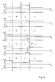
- the electronic control device 13 shown in FIG. 3 has a central unit 15 with a plurality of electronic switches 1.
- the electronic switches 1 correspond to FIG. 1, the grounding 6 being omitted.
- the electronic switches 1 connect loads 16 to a supply voltage 14 via load lines 17. This applies with the exception of an electronic switch 1, which is connected to an information line 18 on the output side.
- the information line 18 is in each case connected to one of the load lines 17 via information switches 19.
- Diodes 20 are connected in series with the information switch 19, the transmission direction of which runs from the information line 18 to the load lines 17.
Landscapes
- Engineering & Computer Science (AREA)
- Power Engineering (AREA)
- Selective Calling Equipment (AREA)
- Remote Monitoring And Control Of Power-Distribution Networks (AREA)
- Electronic Switches (AREA)
- Keying Circuit Devices (AREA)
- Magnetically Actuated Valves (AREA)
- Direct Current Feeding And Distribution (AREA)
- Testing Of Short-Circuits, Discontinuities, Leakage, Or Incorrect Line Connections (AREA)
- Networks Using Active Elements (AREA)
- Oscillators With Electromechanical Resonators (AREA)
- Measurement Of Resistance Or Impedance (AREA)
- Glass Compositions (AREA)
Applications Claiming Priority (2)
| Application Number | Priority Date | Filing Date | Title |
|---|---|---|---|
| DE4140587A DE4140587C2 (de) | 1991-12-10 | 1991-12-10 | Elektronische Steuereinrichtung zum Schalten mehrerer elektrischer Lasten |
| DE4140587 | 1991-12-10 |
Publications (3)
| Publication Number | Publication Date |
|---|---|
| EP0546455A2 true EP0546455A2 (fr) | 1993-06-16 |
| EP0546455A3 EP0546455A3 (en) | 1993-12-22 |
| EP0546455B1 EP0546455B1 (fr) | 1996-03-20 |
Family
ID=6446644
Family Applications (1)
| Application Number | Title | Priority Date | Filing Date |
|---|---|---|---|
| EP92120681A Expired - Lifetime EP0546455B1 (fr) | 1991-12-10 | 1992-12-04 | Unité de commande électronique pour commuter plusieurs charges électriques |
Country Status (10)
| Country | Link |
|---|---|
| US (1) | US5436788A (fr) |
| EP (1) | EP0546455B1 (fr) |
| JP (1) | JP3187990B2 (fr) |
| KR (1) | KR100280577B1 (fr) |
| AT (1) | ATE135854T1 (fr) |
| CA (1) | CA2084978A1 (fr) |
| DE (2) | DE4140587C2 (fr) |
| DK (1) | DK0546455T3 (fr) |
| FI (1) | FI925156A7 (fr) |
| ZA (1) | ZA929579B (fr) |
Families Citing this family (24)
| Publication number | Priority date | Publication date | Assignee | Title |
|---|---|---|---|---|
| JPH08506709A (ja) * | 1993-04-21 | 1996-07-16 | シク パーク、ヒュン | スイッチングシステム |
| US5687052A (en) * | 1996-03-14 | 1997-11-11 | Paragon Electric Company, Inc. | Flexible variable pole-count relay output circuit for controlling multiple relays |
| US6392318B1 (en) | 1998-10-28 | 2002-05-21 | Eigenpoint Company | Programmable emergency-stop circuit |
| US6734581B1 (en) | 1998-10-28 | 2004-05-11 | Eigenpoint Company | Programmable emergency-stop circuit with testing |
| DE10042249A1 (de) * | 2000-08-29 | 2002-03-28 | Bosch Gmbh Robert | Digitaler Drehschalter |
| DE10061025B4 (de) * | 2000-12-08 | 2014-11-27 | Bayerische Motoren Werke Aktiengesellschaft | Mehrstellungs-Schalter-Anordnung in Kraftfahrzeugen |
| DE10061024B4 (de) * | 2000-12-08 | 2014-12-11 | Bayerische Motoren Werke Aktiengesellschaft | Mehrstellungs-Schalter-Anordnung in Kraftfahrzeugen |
| US7348690B2 (en) * | 2002-02-25 | 2008-03-25 | Alfred Wade Muldoon | Preventing unsafe operation by monitoring switching means |
| US7075769B2 (en) * | 2002-04-10 | 2006-07-11 | Pent Technologies, Inc. | Next connect electrical receptacle assembly |
| US8624601B2 (en) | 2010-10-04 | 2014-01-07 | Enerdel, Inc. | System and method for determining physical status of switch elements |
| US8766490B2 (en) | 2011-03-25 | 2014-07-01 | Enerdel, Inc. | System and method for monitoring operation of switch elements |
| CA2774364C (fr) | 2011-04-18 | 2014-01-28 | Norman R. Byrne | Systeme electrique a circuit limiteur |
| US10240870B2 (en) | 2015-01-26 | 2019-03-26 | Spex Sample Prep, Llc | Method for operating a power-compensated fusion furnace |
| US11513042B2 (en) * | 2015-01-26 | 2022-11-29 | SPEX SamplePrep, LLC | Power-compensated fusion furnace |
| CA2981704C (fr) | 2016-10-07 | 2020-10-20 | Norman R. Byrne | Cordon d'alimentation electrique dote d'un interrupteur intelligent |
| US10186900B2 (en) | 2017-02-24 | 2019-01-22 | Ergotron, Inc. | Techniques for controlling A/C power distribution in powered furniture |
| US10348089B2 (en) | 2017-05-31 | 2019-07-09 | Ergotron, Inc. | Techniques for controlling A/C power distribution in powered furniture |
| US10915084B2 (en) * | 2018-03-12 | 2021-02-09 | Rosemount Inc. | Field device switch monitor |
| US11004637B2 (en) * | 2018-03-22 | 2021-05-11 | Rosemount Inc. | Field device latching relay reset |
| US11424561B2 (en) | 2019-07-03 | 2022-08-23 | Norman R. Byrne | Outlet-level electrical energy management system |
| US11821951B2 (en) | 2021-09-29 | 2023-11-21 | Rosemount Inc. | Field device switch monitoring |
| US12218775B2 (en) | 2022-12-19 | 2025-02-04 | Rosemount Inc. | Advanced physical layer (APL) adapter for legacy field devices |
| US12517483B2 (en) | 2023-06-22 | 2026-01-06 | Rosemount Inc. | Field device with latching relay |
| US12493315B2 (en) | 2024-04-30 | 2025-12-09 | Rosemount Inc. | Ethernet-APL field device having reduced energy consumption |
Family Cites Families (6)
| Publication number | Priority date | Publication date | Assignee | Title |
|---|---|---|---|---|
| US4418333A (en) * | 1981-06-08 | 1983-11-29 | Pittway Corporation | Appliance control system |
| JPS5952992A (ja) * | 1982-09-20 | 1984-03-27 | Matsushita Electric Works Ltd | 多重伝送制御システム |
| EP0364466A4 (en) * | 1987-06-12 | 1991-09-25 | Starec Nominees Pty. Ltd. | Electrical control apparatus |
| US5006724A (en) | 1989-03-20 | 1991-04-09 | Liu Ching Chung | Control device for light sets |
| DE4015271A1 (de) * | 1990-05-12 | 1991-11-14 | Vdo Schindling | Schaltungsanordnung zur abfrage von schalterstellungen |
| DE4019059A1 (de) * | 1990-06-15 | 1991-12-19 | Bosch Gmbh Robert | Vorrichtung zum ein- und ausschalten einer last |
-
1991
- 1991-12-10 DE DE4140587A patent/DE4140587C2/de not_active Expired - Fee Related
-
1992
- 1992-11-12 FI FI925156A patent/FI925156A7/fi unknown
- 1992-11-26 KR KR1019920022436A patent/KR100280577B1/ko not_active Expired - Fee Related
- 1992-11-30 JP JP32080192A patent/JP3187990B2/ja not_active Expired - Fee Related
- 1992-12-04 EP EP92120681A patent/EP0546455B1/fr not_active Expired - Lifetime
- 1992-12-04 AT AT92120681T patent/ATE135854T1/de not_active IP Right Cessation
- 1992-12-04 DE DE59205759T patent/DE59205759D1/de not_active Expired - Fee Related
- 1992-12-04 DK DK92120681.9T patent/DK0546455T3/da active
- 1992-12-09 US US07/987,743 patent/US5436788A/en not_active Expired - Lifetime
- 1992-12-09 CA CA002084978A patent/CA2084978A1/fr not_active Abandoned
- 1992-12-10 ZA ZA929579A patent/ZA929579B/xx unknown
Also Published As
| Publication number | Publication date |
|---|---|
| CA2084978A1 (fr) | 1993-06-11 |
| DE4140587C2 (de) | 1994-09-08 |
| ATE135854T1 (de) | 1996-04-15 |
| JP3187990B2 (ja) | 2001-07-16 |
| KR930015433A (ko) | 1993-07-24 |
| FI925156A0 (fi) | 1992-11-12 |
| DE59205759D1 (de) | 1996-04-25 |
| EP0546455B1 (fr) | 1996-03-20 |
| FI925156A7 (fi) | 1993-06-11 |
| JPH05280658A (ja) | 1993-10-26 |
| KR100280577B1 (ko) | 2001-03-02 |
| ZA929579B (en) | 1993-06-11 |
| DE4140587A1 (de) | 1993-06-17 |
| EP0546455A3 (en) | 1993-12-22 |
| US5436788A (en) | 1995-07-25 |
| DK0546455T3 (da) | 1996-06-17 |
Similar Documents
| Publication | Publication Date | Title |
|---|---|---|
| EP0546455B1 (fr) | Unité de commande électronique pour commuter plusieurs charges électriques | |
| DE3110836C2 (de) | Eingangs-Schnittstelleneinheit für eine programmierbare logische Steuereinheit | |
| DE60005365T2 (de) | Elektrische isolierungsvorrichtung mit optokoppler für bidirektionelle anschlussleitungen | |
| DE3713262A1 (de) | Steckverbindungs-codierung fuer elektrische kabel | |
| DE69811950T2 (de) | Elektronische überwachungsschaltung für elektrische spannung | |
| EP3491472A1 (fr) | Module série, module de connexion et système de commande de conception modulaire | |
| DE2316754A1 (de) | Fehlerart-feststellungssystem | |
| DE10152653A1 (de) | Vorrichtung zur eigensicheren redundanten Strom-Spannungsversorgung | |
| DE2944370B2 (de) | Schaltung zur Isolierung von Datenquellen gegen eine gemeinschaftlich zu verschiedenen Zeiten benutzte Datenschiene | |
| EP4336201A1 (fr) | Montage de test simplifié pour le test de faisceaux de câbles | |
| DE3638681C2 (fr) | ||
| DE102018206804A1 (de) | Erkennung von Unterbrechungen eines Stromkreises | |
| DE10059179C1 (de) | Schaltungsanordnung für eine Antennenanordnung und Verfahren zum Schalten einer Antennenanordnung | |
| EP1364380B1 (fr) | Commutateur electrique | |
| EP4248474B1 (fr) | Dispositif adaptateur | |
| EP0670033B1 (fr) | Circuit pour le traitement de signaux analogiques de courant et de tension | |
| EP0940066B1 (fr) | Dispositif de codage d'unites enfichables et dispositif de connexion de lignes exterieures au moyen d'un tel dispositif de codage | |
| DE10111468B4 (de) | Verfahren und Vorrichtung zur Ermittlung von Eigenschaften gesteckter Module | |
| EP0269952A2 (fr) | Système d'alimentation de courant tolérant des défauts, de forme annulaire | |
| DE2460245A1 (de) | Funktionsueberwachungsanordnung fuer schaltkreise mit im betrieb geringem stromverbrauch, insbesondere fuer komplementaere mos-schaltkreise | |
| EP0202684A2 (fr) | Procédé pour la commande sélective de circuits électriques ainsi que montage pour l'exécution du procédé | |
| EP0822471B1 (fr) | Dispositif électronique | |
| DE19934077C2 (de) | Anordnung zur Betätigung elektrischer Funktionselemente | |
| EP0396812A1 (fr) | Commutateur à seuil | |
| DE3641528C2 (fr) |
Legal Events
| Date | Code | Title | Description |
|---|---|---|---|
| PUAI | Public reference made under article 153(3) epc to a published international application that has entered the european phase |
Free format text: ORIGINAL CODE: 0009012 |
|
| AK | Designated contracting states |
Kind code of ref document: A2 Designated state(s): AT BE CH DE DK ES FR GB GR IE IT LI LU MC NL PT SE |
|
| PUAL | Search report despatched |
Free format text: ORIGINAL CODE: 0009013 |
|
| AK | Designated contracting states |
Kind code of ref document: A3 Designated state(s): AT BE CH DE DK ES FR GB GR IE IT LI LU MC NL PT SE |
|
| 17P | Request for examination filed |
Effective date: 19940204 |
|
| 17Q | First examination report despatched |
Effective date: 19950810 |
|
| GRAA | (expected) grant |
Free format text: ORIGINAL CODE: 0009210 |
|
| ITF | It: translation for a ep patent filed | ||
| AK | Designated contracting states |
Kind code of ref document: B1 Designated state(s): AT BE CH DE DK ES FR GB GR IE IT LI LU MC NL PT SE |
|
| PG25 | Lapsed in a contracting state [announced via postgrant information from national office to epo] |
Ref country code: NL Free format text: LAPSE BECAUSE OF FAILURE TO SUBMIT A TRANSLATION OF THE DESCRIPTION OR TO PAY THE FEE WITHIN THE PRESCRIBED TIME-LIMIT Effective date: 19960320 Ref country code: GR Free format text: LAPSE BECAUSE OF FAILURE TO SUBMIT A TRANSLATION OF THE DESCRIPTION OR TO PAY THE FEE WITHIN THE PRESCRIBED TIME-LIMIT Effective date: 19960320 Ref country code: ES Free format text: THE PATENT HAS BEEN ANNULLED BY A DECISION OF A NATIONAL AUTHORITY Effective date: 19960320 |
|
| REF | Corresponds to: |
Ref document number: 135854 Country of ref document: AT Date of ref document: 19960415 Kind code of ref document: T |
|
| GBT | Gb: translation of ep patent filed (gb section 77(6)(a)/1977) |
Effective date: 19960320 |
|
| REG | Reference to a national code |
Ref country code: IE Ref legal event code: FG4D Free format text: 67670 |
|
| REF | Corresponds to: |
Ref document number: 59205759 Country of ref document: DE Date of ref document: 19960425 |
|
| ET | Fr: translation filed | ||
| REG | Reference to a national code |
Ref country code: DK Ref legal event code: T3 |
|
| PG25 | Lapsed in a contracting state [announced via postgrant information from national office to epo] |
Ref country code: PT Effective date: 19960620 |
|
| GRAH | Despatch of communication of intention to grant a patent |
Free format text: ORIGINAL CODE: EPIDOS IGRA |
|
| NLV1 | Nl: lapsed or annulled due to failure to fulfill the requirements of art. 29p and 29m of the patents act | ||
| PG25 | Lapsed in a contracting state [announced via postgrant information from national office to epo] |
Ref country code: IE Free format text: LAPSE BECAUSE OF NON-PAYMENT OF DUE FEES Effective date: 19961107 |
|
| REG | Reference to a national code |
Ref country code: IE Ref legal event code: FD4D Ref document number: 67670 Country of ref document: IE |
|
| PG25 | Lapsed in a contracting state [announced via postgrant information from national office to epo] |
Ref country code: LU Free format text: LAPSE BECAUSE OF NON-PAYMENT OF DUE FEES Effective date: 19961231 Ref country code: LI Effective date: 19961231 Ref country code: CH Effective date: 19961231 |
|
| PLBE | No opposition filed within time limit |
Free format text: ORIGINAL CODE: 0009261 |
|
| STAA | Information on the status of an ep patent application or granted ep patent |
Free format text: STATUS: NO OPPOSITION FILED WITHIN TIME LIMIT |
|
| 26N | No opposition filed | ||
| PG25 | Lapsed in a contracting state [announced via postgrant information from national office to epo] |
Ref country code: MC Effective date: 19970630 |
|
| REG | Reference to a national code |
Ref country code: CH Ref legal event code: PL |
|
| REG | Reference to a national code |
Ref country code: GB Ref legal event code: IF02 |
|
| PGFP | Annual fee paid to national office [announced via postgrant information from national office to epo] |
Ref country code: FR Payment date: 20021119 Year of fee payment: 11 |
|
| PGFP | Annual fee paid to national office [announced via postgrant information from national office to epo] |
Ref country code: SE Payment date: 20021120 Year of fee payment: 11 Ref country code: AT Payment date: 20021120 Year of fee payment: 11 |
|
| PGFP | Annual fee paid to national office [announced via postgrant information from national office to epo] |
Ref country code: DK Payment date: 20021122 Year of fee payment: 11 |
|
| PGFP | Annual fee paid to national office [announced via postgrant information from national office to epo] |
Ref country code: GB Payment date: 20021127 Year of fee payment: 11 |
|
| PGFP | Annual fee paid to national office [announced via postgrant information from national office to epo] |
Ref country code: BE Payment date: 20021218 Year of fee payment: 11 |
|
| PGFP | Annual fee paid to national office [announced via postgrant information from national office to epo] |
Ref country code: DE Payment date: 20021230 Year of fee payment: 11 |
|
| PG25 | Lapsed in a contracting state [announced via postgrant information from national office to epo] |
Ref country code: GB Free format text: LAPSE BECAUSE OF NON-PAYMENT OF DUE FEES Effective date: 20031204 Ref country code: AT Free format text: LAPSE BECAUSE OF NON-PAYMENT OF DUE FEES Effective date: 20031204 |
|
| PG25 | Lapsed in a contracting state [announced via postgrant information from national office to epo] |
Ref country code: SE Free format text: LAPSE BECAUSE OF NON-PAYMENT OF DUE FEES Effective date: 20031205 |
|
| PG25 | Lapsed in a contracting state [announced via postgrant information from national office to epo] |
Ref country code: BE Free format text: LAPSE BECAUSE OF NON-PAYMENT OF DUE FEES Effective date: 20031231 |
|
| PG25 | Lapsed in a contracting state [announced via postgrant information from national office to epo] |
Ref country code: DK Free format text: LAPSE BECAUSE OF NON-PAYMENT OF DUE FEES Effective date: 20040102 |
|
| BERE | Be: lapsed |
Owner name: *CLARK EQUIPMENT CY Effective date: 20031231 |
|
| PG25 | Lapsed in a contracting state [announced via postgrant information from national office to epo] |
Ref country code: DE Free format text: LAPSE BECAUSE OF NON-PAYMENT OF DUE FEES Effective date: 20040701 |
|
| GBPC | Gb: european patent ceased through non-payment of renewal fee |
Effective date: 20031204 |
|
| EUG | Se: european patent has lapsed | ||
| REG | Reference to a national code |
Ref country code: DK Ref legal event code: EBP |
|
| PG25 | Lapsed in a contracting state [announced via postgrant information from national office to epo] |
Ref country code: FR Free format text: LAPSE BECAUSE OF NON-PAYMENT OF DUE FEES Effective date: 20040831 |
|
| REG | Reference to a national code |
Ref country code: FR Ref legal event code: ST |
|
| PG25 | Lapsed in a contracting state [announced via postgrant information from national office to epo] |
Ref country code: IT Free format text: LAPSE BECAUSE OF NON-PAYMENT OF DUE FEES;WARNING: LAPSES OF ITALIAN PATENTS WITH EFFECTIVE DATE BEFORE 2007 MAY HAVE OCCURRED AT ANY TIME BEFORE 2007. THE CORRECT EFFECTIVE DATE MAY BE DIFFERENT FROM THE ONE RECORDED. Effective date: 20051204 |