EP0546557A2 - Disque d'embrayage pour un embrayage à friction de véhicule - Google Patents
Disque d'embrayage pour un embrayage à friction de véhicule Download PDFInfo
- Publication number
- EP0546557A2 EP0546557A2 EP92121099A EP92121099A EP0546557A2 EP 0546557 A2 EP0546557 A2 EP 0546557A2 EP 92121099 A EP92121099 A EP 92121099A EP 92121099 A EP92121099 A EP 92121099A EP 0546557 A2 EP0546557 A2 EP 0546557A2
- Authority
- EP
- European Patent Office
- Prior art keywords
- hub
- spring tongues
- clutch
- clutch disc
- disc according
- Prior art date
- Legal status (The legal status is an assumption and is not a legal conclusion. Google has not performed a legal analysis and makes no representation as to the accuracy of the status listed.)
- Granted
Links
- 210000002105 tongue Anatomy 0.000 claims abstract description 52
- 239000002184 metal Substances 0.000 claims description 10
- 239000004033 plastic Substances 0.000 claims description 8
- 239000002131 composite material Substances 0.000 claims description 5
- 230000008878 coupling Effects 0.000 claims description 5
- 238000010168 coupling process Methods 0.000 claims description 5
- 238000005859 coupling reaction Methods 0.000 claims description 5
- 239000002991 molded plastic Substances 0.000 claims description 5
- 238000000465 moulding Methods 0.000 claims description 2
- 238000004519 manufacturing process Methods 0.000 description 3
- 230000005540 biological transmission Effects 0.000 description 2
- 239000000463 material Substances 0.000 description 2
- 239000000872 buffer Substances 0.000 description 1
- 238000002485 combustion reaction Methods 0.000 description 1
- 230000000694 effects Effects 0.000 description 1
- 238000001125 extrusion Methods 0.000 description 1
- 238000002347 injection Methods 0.000 description 1
- 239000007924 injection Substances 0.000 description 1
- 238000003754 machining Methods 0.000 description 1
- 230000000750 progressive effect Effects 0.000 description 1
- 238000000926 separation method Methods 0.000 description 1
Images


Classifications
-
- F—MECHANICAL ENGINEERING; LIGHTING; HEATING; WEAPONS; BLASTING
- F16—ENGINEERING ELEMENTS AND UNITS; GENERAL MEASURES FOR PRODUCING AND MAINTAINING EFFECTIVE FUNCTIONING OF MACHINES OR INSTALLATIONS; THERMAL INSULATION IN GENERAL
- F16F—SPRINGS; SHOCK-ABSORBERS; MEANS FOR DAMPING VIBRATION
- F16F15/00—Suppression of vibrations in systems; Means or arrangements for avoiding or reducing out-of-balance forces, e.g. due to motion
- F16F15/10—Suppression of vibrations in rotating systems by making use of members moving with the system
- F16F15/12—Suppression of vibrations in rotating systems by making use of members moving with the system using elastic members or friction-damping members, e.g. between a rotating shaft and a gyratory mass mounted thereon
- F16F15/121—Suppression of vibrations in rotating systems by making use of members moving with the system using elastic members or friction-damping members, e.g. between a rotating shaft and a gyratory mass mounted thereon using springs as elastic members, e.g. metallic springs
- F16F15/123—Wound springs
- F16F15/12313—Wound springs characterised by the dimension or shape of spring-containing windows
-
- F—MECHANICAL ENGINEERING; LIGHTING; HEATING; WEAPONS; BLASTING
- F16—ENGINEERING ELEMENTS AND UNITS; GENERAL MEASURES FOR PRODUCING AND MAINTAINING EFFECTIVE FUNCTIONING OF MACHINES OR INSTALLATIONS; THERMAL INSULATION IN GENERAL
- F16F—SPRINGS; SHOCK-ABSORBERS; MEANS FOR DAMPING VIBRATION
- F16F15/00—Suppression of vibrations in systems; Means or arrangements for avoiding or reducing out-of-balance forces, e.g. due to motion
- F16F15/10—Suppression of vibrations in rotating systems by making use of members moving with the system
- F16F15/12—Suppression of vibrations in rotating systems by making use of members moving with the system using elastic members or friction-damping members, e.g. between a rotating shaft and a gyratory mass mounted thereon
-
- F—MECHANICAL ENGINEERING; LIGHTING; HEATING; WEAPONS; BLASTING
- F16—ENGINEERING ELEMENTS AND UNITS; GENERAL MEASURES FOR PRODUCING AND MAINTAINING EFFECTIVE FUNCTIONING OF MACHINES OR INSTALLATIONS; THERMAL INSULATION IN GENERAL
- F16F—SPRINGS; SHOCK-ABSORBERS; MEANS FOR DAMPING VIBRATION
- F16F15/00—Suppression of vibrations in systems; Means or arrangements for avoiding or reducing out-of-balance forces, e.g. due to motion
- F16F15/10—Suppression of vibrations in rotating systems by making use of members moving with the system
- F16F15/12—Suppression of vibrations in rotating systems by making use of members moving with the system using elastic members or friction-damping members, e.g. between a rotating shaft and a gyratory mass mounted thereon
- F16F15/1207—Suppression of vibrations in rotating systems by making use of members moving with the system using elastic members or friction-damping members, e.g. between a rotating shaft and a gyratory mass mounted thereon characterised by the supporting arrangement of the damper unit
-
- F—MECHANICAL ENGINEERING; LIGHTING; HEATING; WEAPONS; BLASTING
- F16—ENGINEERING ELEMENTS AND UNITS; GENERAL MEASURES FOR PRODUCING AND MAINTAINING EFFECTIVE FUNCTIONING OF MACHINES OR INSTALLATIONS; THERMAL INSULATION IN GENERAL
- F16F—SPRINGS; SHOCK-ABSORBERS; MEANS FOR DAMPING VIBRATION
- F16F15/00—Suppression of vibrations in systems; Means or arrangements for avoiding or reducing out-of-balance forces, e.g. due to motion
- F16F15/10—Suppression of vibrations in rotating systems by making use of members moving with the system
- F16F15/12—Suppression of vibrations in rotating systems by making use of members moving with the system using elastic members or friction-damping members, e.g. between a rotating shaft and a gyratory mass mounted thereon
- F16F15/121—Suppression of vibrations in rotating systems by making use of members moving with the system using elastic members or friction-damping members, e.g. between a rotating shaft and a gyratory mass mounted thereon using springs as elastic members, e.g. metallic springs
- F16F15/123—Wound springs
- F16F15/1238—Wound springs with pre-damper, i.e. additional set of springs between flange of main damper and hub
-
- F—MECHANICAL ENGINEERING; LIGHTING; HEATING; WEAPONS; BLASTING
- F16—ENGINEERING ELEMENTS AND UNITS; GENERAL MEASURES FOR PRODUCING AND MAINTAINING EFFECTIVE FUNCTIONING OF MACHINES OR INSTALLATIONS; THERMAL INSULATION IN GENERAL
- F16F—SPRINGS; SHOCK-ABSORBERS; MEANS FOR DAMPING VIBRATION
- F16F2224/00—Materials; Material properties
Definitions
- the invention relates to a clutch disc for a motor vehicle friction clutch.
- a clutch disc for a motor vehicle friction clutch is known, the hub rotatably carries a hub disc and two axially on both sides of the hub disc firmly connected and torsionally elastic with the hub disc coupled side windows are rotatably arranged.
- One of the side windows has clutch friction linings.
- the hub engages in central openings of the two side disks and is guided radially on one of the two side disks by an axially arranged ring between this side disk and the hub disk, which with axially projecting spring tongues engages in an annular gap between the hub and the central opening of the one side disk.
- the improvement according to the invention consists in the fact that the guide area of the hub has a plurality of radially resilient spring tongues which are distributed in the circumferential direction of the hub and are firmly connected to the hub and which extend into the central opening of the one side disk and rest there under radial prestress on the one side disk .
- the side disks can be elastically centered on the hub without additional components.
- Both the z. B. side plates designed as cover plates and the hub can thus be produced with relatively large tolerances. Since the components are guided radially elastically to one another, misalignments between the internal combustion engine and the transmission of the motor vehicle can be compensated for at this point. At the same time, the components involved in the elastic centering serve to generate a basic friction of the torsional vibration damper device integrated in the clutch disc.
- the maximum spring travel between the side window and the hub is limited by rigid stops which are provided on the hub.
- the stops have a smaller average diameter compared to the central opening of one side window.
- a more or less rigid stop is effective, depending on the material used, which on the one hand protects the spring tongues from overloading and on the other hand a very flat area in their initial area, i.e. only slight and only with little deflection little changing spring force generating spring characteristic enables.
- the stops are part of the spring tongues.
- the stops are also possible to arrange the stops independently of the spring tongues, that is to say in the circumferential direction at a distance from and between the spring tongues. In this way, these components can be designed independently of each other.
- the spring tongues run essentially in the axial direction. This allows particularly good centering to be achieved.
- the spring tongues are curved in an arc and run in the circumferential direction. In this embodiment, a relatively large spring travel is made possible.
- spring tongues are connected to the hub at their two ends and are resiliently curved radially outwards in their central region.
- This embodiment has particularly good strength properties and the spring characteristic can be made very progressive.
- the spring tongues are firmly connected to the hub at one end, while the other end is designed to be radially freely resilient. Such an arrangement is particularly space-saving and enables sufficiently large spring travel.
- the hub including the teeth and the hub disc of the idle vibration damper is made entirely as a molded plastic part.
- the spring tongues can also be provided integrally on the molded part.
- the hub can be designed as a composite molded part consisting of a plastic molded part, into which a metal molded part is inserted.
- the metal molded part comprises at least the toothing mentioned above for fitting the hub disk, while the further hub disk is molded onto the plastic molded part.
- This arrangement lends itself to applications in which the toothing is particularly heavily loaded.
- the metal molded part can be produced exactly on its own and is then advantageously extrusion-coated during the production of the plastic molded part.
- the spring tongues are preferably formed in one piece on the metal molding forming the toothing.
- the spring tongues are preferably provided with a threading bevel at their area facing the central opening of the side window. In this way, the assembly of the side window and hub can be made considerably easier since the spring tongues can be inserted axially into the opening of the side window without any problems.
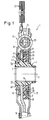
- FIG. 1 shows a clutch disc 1, the individual parts of which are arranged concentrically with an axis of rotation 3.
- a hub 5 designed as a plastic molded part has in its inner opening an internal toothing 7 for non-rotatably mounting on a transmission input shaft, not shown.
- the hub 5 is provided with teeth 9 into which a hub disk 11 of a load-torsional vibration damper of the clutch disk, generally designated 13, has a toothing 15 in a rotationally fixed manner, but with a rotational play determining the effective range of an idle torsional vibration damper 17, which will be explained in more detail below intervenes.
- side disks 21, 23 which are firmly connected to one another and kept at a distance from one another are rotatably arranged relative to the hub 5 by rivets 19.
- the side disks 21, 23 are coupled to the hub disk 11 in a torsionally elastic manner by means of coil springs 25, which are seated in windows of the side disks 21, 23 on the one hand and the hub disk 11 on the other hand.
- the side window 21 also carries clutch friction linings 27.
- a hub disk 29 of the idle torsional vibration damper 17 is non-rotatably placed on the hub 5.
- the hub disk 29 receives helical springs 33 of the idle damper 17 in recesses 31.
- a control part 35 is arranged axially next to the hub disk 29 arranged radially within the area of the coil springs 25, which is coupled via projections 37 to the hub disk 11 and via projections 39 to the coil springs 33 of the idle damper 17.
- a friction ring 41 of a load-rubbing device which bears against the hub disk 11 and which is non-rotatably connected to the side disk 21 and is tensioned against the hub disk 11 by a plate spring 43.
- the force path of the plate spring 43 closes via the other side disk 23 and the control part 35 supported on the hub disk 11 via the projections 37.
- a corrugated spring 45 is arranged radially inside the friction ring 41, which is supported on the one hand on the inside of the side disk 21 and on the other hand on the teeth 9 of the hub 5.
- the wave spring 45 generates a basic friction that is effective both in the idling range and in the load range.
- One of the two side windows 21, 23, here the side window 21 has an opening 47 which is concentric with the axis of rotation and which in the present case is delimited by an axially flared collar 49.
- the collar 49 serves to stiffen the side window 21 and to enlarge the contact surfaces of spring tongues 51 which protrude axially from the hub 5 and engage in the central opening 47 of the side window 21.
- the inherently elastic spring tongues 51 are biased radially outward against the central opening 47 and center the side disk 21 relative to the hub 5. All other components of the clutch disk 1 rotatable relative to the hub 5 are thus centered relative to the axis of rotation 3 via the side disk 21.
- the hub 5 is including the spring tongues 51 and the teeth 9 as a molded plastic part educated. Such a one-piece embodiment is particularly economical to produce. It is understood that the collar 49 can be omitted if necessary.
- a hub 5a is shown, the spring tongues 51 a are arranged extending in the circumferential direction and with one end 53 are fixedly connected to a substantially sleeve-shaped hub body 55 of the hub 5a, while the free other end 57 for centering the Side window 21 is used.
- the resilient end regions 57 of the spring tongues 51 a define a circumference which is concentric with the axis of rotation 3a and which is greater than the circumference defined by the ends 53 firmly connected to the hub body 55 at the ends.
- the circumferential diameter of the ends 53 is smaller than the inner diameter of the central opening 47 of the side window 21.
- the ends 53 which also engage in the central opening 47 (FIG.
- the side window 21 thus form stops which limit the radial spring travel of the spring tongues 51 a and Protect spring tongues 51a against overload.
- the stops or ends 53 limit the maximum radial deflection of the side disks 21, 23 relative to the hub 5a.
- the spring tongues 51 a are provided on their both axially and radially outer edges with threading bevels 59, which considerably facilitate the assembly of the side window 21 and the hub 5 a, since they constrain the non-installed state a larger diameter resilient tongues 51 a in the central opening 47 of the side window 21 facilitate.
- FIG. 5 shows a section of a variant of the hub from FIG. 2, in which spring tongues 51 b extending elongated in the circumferential direction are integrally held on the hub 5 b at both ends 53 b.
- the spring tongues 51b are arched radially outward in their central region located between the ends 53b and here are designed to be radially resilient.
- stops 61 are formed on the hub 5b formed as a plastic molded body. The stops 61 in turn define a smaller circumferential diameter than the inner diameter of the central opening 47 of the side plate 21, so that they limit the spring travel in the manner explained above.
- stops 61 are provided separately from the spring tongues 51, a functional separation can be achieved which allows the stops 61 to be optimized independently of the spring tongues 51 b. It is understood that the stops 61, after they are made of plastic, do not have to form absolutely firm stops, but can also form resilient buffers to a limited extent within the framework of the elasticity of the material used.
- FIG. 6 shows a variant of a hub 5c designed as a composite molded part, which has a toothed molded part 63 made of metal, onto which a molded plastic part 67 comprising the hub flange 29c and a sleeve part 65 carrying the internal toothing 7c is injection molded.
- the toothing part 63 has the teeth to be coupled with the hub disk 11 and spring tongues 51 projecting axially here integrally formed.
- the production of the hub 5c as a composite part has the advantage that there are no strength problems in the toothed area 9c under high loads. In such a case, the teeth can also be made very compact.
- the elastic properties of the metal are used for the spring tongues 51c.
- the side window 21 can be mounted with the central opening 47 of its collar 49 directly on the outer circumference of the spring tongues 51 c.
Landscapes
- Engineering & Computer Science (AREA)
- General Engineering & Computer Science (AREA)
- Physics & Mathematics (AREA)
- Acoustics & Sound (AREA)
- Aviation & Aerospace Engineering (AREA)
- Mechanical Engineering (AREA)
- Mechanical Operated Clutches (AREA)
Applications Claiming Priority (2)
| Application Number | Priority Date | Filing Date | Title |
|---|---|---|---|
| DE4140643A DE4140643C2 (de) | 1991-12-10 | 1991-12-10 | Kupplungsscheibe mit elastischer Zentrierung |
| DE4140643 | 1991-12-10 |
Publications (3)
| Publication Number | Publication Date |
|---|---|
| EP0546557A2 true EP0546557A2 (fr) | 1993-06-16 |
| EP0546557A3 EP0546557A3 (fr) | 1994-01-05 |
| EP0546557B1 EP0546557B1 (fr) | 1996-02-14 |
Family
ID=6446677
Family Applications (1)
| Application Number | Title | Priority Date | Filing Date |
|---|---|---|---|
| EP92121099A Expired - Lifetime EP0546557B1 (fr) | 1991-12-10 | 1992-12-10 | Disque d'embrayage pour un embrayage à friction de véhicule |
Country Status (5)
| Country | Link |
|---|---|
| US (1) | US5251736A (fr) |
| EP (1) | EP0546557B1 (fr) |
| BR (1) | BR9204956A (fr) |
| DE (2) | DE4140643C2 (fr) |
| ES (1) | ES2086054T3 (fr) |
Cited By (4)
| Publication number | Priority date | Publication date | Assignee | Title |
|---|---|---|---|---|
| FR2695443A1 (fr) * | 1992-09-10 | 1994-03-11 | Fichtel & Sachs Ag | Disque d'embrayage avec anneau radial élastique en matière plastique. |
| WO1998036188A1 (fr) * | 1997-02-14 | 1998-08-20 | Valeo | Moyeu pour preamortisseur notamment pour vehicule automobile et dispositif amortisseur de torsion comportant un tel moyeu |
| FR2785957A1 (fr) * | 1998-11-18 | 2000-05-19 | Valeo | Amortisseur de torsion pour disque d'embrayage a friction |
| FR2792698A1 (fr) * | 1999-04-22 | 2000-10-27 | Valeo | Amortisseur de torsion pour embrayage, en particulier de vehicule automobile |
Families Citing this family (10)
| Publication number | Priority date | Publication date | Assignee | Title |
|---|---|---|---|---|
| FR2706005B1 (fr) * | 1993-06-02 | 1995-07-28 | Valeo | Sous-ensemble unitaire de frottement pour amortisseur de torsion. |
| GB2283557B (en) * | 1993-11-05 | 1998-03-25 | Luk Lamellen & Kupplungsbau | Rotary vibration damper |
| GB2283558B (en) * | 1993-11-05 | 1998-03-25 | Luk Lamellen & Kupplungsbau | Rotary vibration damper |
| DE4407766A1 (de) * | 1994-03-09 | 1995-09-14 | Fichtel & Sachs Ag | Kupplungsscheibe mit einer versteiften Nabe |
| DE19514734C2 (de) * | 1994-04-25 | 1999-11-18 | Exedy Corp | Kupplungsscheibenausbildung |
| DE4429870A1 (de) * | 1994-08-23 | 1996-02-29 | Fichtel & Sachs Ag | Kupplungsscheibe mit geteilter Nabenscheibe |
| FR2726618B1 (fr) * | 1994-11-08 | 1996-12-13 | Valeo | Amortisseur de torsion, notamment friction d'embrayage pour vehicule automobile |
| US6135890A (en) * | 1996-12-11 | 2000-10-24 | Luk Lamellen Und Kupplungsbau Gmbh | Torsional vibration damper |
| JP2000002263A (ja) * | 1998-06-16 | 2000-01-07 | Exedy Corp | ブッシュ |
| DE19929940A1 (de) * | 1999-06-29 | 2001-01-18 | Mannesmann Sachs Ag | Kupplungsscheibe |
Family Cites Families (19)
| Publication number | Priority date | Publication date | Assignee | Title |
|---|---|---|---|---|
| GB1401186A (en) * | 1971-11-19 | 1975-07-16 | Gkn Transmissions Ltd | Clutches |
| JPS5852335U (ja) * | 1981-10-06 | 1983-04-09 | トヨタ自動車株式会社 | クラツチデイスク |
| DE3248120A1 (de) * | 1982-12-24 | 1984-06-28 | LuK Lamellen und Kupplungsbau GmbH, 7580 Bühl | Kupplungsscheibe |
| DE3313850A1 (de) * | 1983-04-16 | 1984-10-18 | LuK Lamellen und Kupplungsbau GmbH, 7580 Bühl | Kupplungsscheibe |
| DE3330343A1 (de) * | 1983-08-23 | 1985-03-14 | Fichtel & Sachs Ag, 8720 Schweinfurt | Kupplungsscheibe mit uebereinander angeordneter leerlauf-reibungsdaempfung und last-reibungsdaempfung |
| DE3334657A1 (de) * | 1983-09-24 | 1985-04-11 | Fichtel & Sachs Ag, 8720 Schweinfurt | Reibungskupplung mit kupplungsscheibe und spielunterdrueckung zwischen nabe und getriebewelle |
| DE3340896A1 (de) * | 1983-11-11 | 1985-05-23 | Fichtel & Sachs Ag, 8720 Schweinfurt | Torsionsschwingungsdaempfer mit spielfreier lagerung und definierter reibung |
| DE3409868A1 (de) * | 1984-03-17 | 1985-09-19 | Fichtel & Sachs Ag, 8720 Schweinfurt | Kupplungsscheibe |
| US4537296A (en) * | 1984-07-23 | 1985-08-27 | Alma Piston Company | Clutch driven plate assembly |
| US4890712A (en) * | 1984-11-23 | 1990-01-02 | Luk Lamellen Und Kupplungsbau Gmbh | Torsional vibration damping device for clutch plates |
| FR2583486B1 (fr) * | 1985-06-14 | 1989-03-31 | Valeo | Dispositif amortisseur de torsion, notamment pour embrayage de vehicule automobile, a amortissement au moins partiellement du a un element elastomere |
| US4651859A (en) * | 1985-07-11 | 1987-03-24 | Borg-Warner Automotive, Inc. | Clutch driven plate assembly with a two-part hub |
| JPH0652088B2 (ja) * | 1985-09-30 | 1994-07-06 | アイシン精機株式会社 | クラツチデイスク |
| FR2614080B1 (fr) * | 1987-04-14 | 1992-04-10 | Valeo | Dispositif amortisseur de torsion a palier de centrage |
| FR2642805B1 (fr) * | 1989-02-07 | 1993-01-22 | Valeo | Dispositif amortisseur de torsion, notamment pour disque de friction d'embrayage de vehicules automobiles |
| DE3921283A1 (de) * | 1989-02-08 | 1990-08-09 | Fichtel & Sachs Ag | Kupplungsscheibe mit torsionsschwingungsdaempfer und radial elastischer lagerung |
| FR2646692B1 (fr) * | 1989-05-02 | 1991-07-05 | Valeo | Dispositif amortisseur de torsion, notamment pour vehicules automobiles |
| DE3922730C2 (de) * | 1989-07-11 | 1997-11-20 | Fichtel & Sachs Ag | Kupplungsscheibe mit Torsionsschwingungsdämpfer |
| FR2663707B1 (fr) * | 1990-06-22 | 1993-04-30 | Valeo | Dispositif amortisseur de torsion, notamment pour disque de friction d'embrayage de vehicule automobile. |
-
1991
- 1991-12-10 DE DE4140643A patent/DE4140643C2/de not_active Expired - Fee Related
-
1992
- 1992-12-08 US US07/987,165 patent/US5251736A/en not_active Expired - Fee Related
- 1992-12-09 BR BR9204956A patent/BR9204956A/pt not_active IP Right Cessation
- 1992-12-10 DE DE59205353T patent/DE59205353D1/de not_active Expired - Fee Related
- 1992-12-10 ES ES92121099T patent/ES2086054T3/es not_active Expired - Lifetime
- 1992-12-10 EP EP92121099A patent/EP0546557B1/fr not_active Expired - Lifetime
Cited By (9)
| Publication number | Priority date | Publication date | Assignee | Title |
|---|---|---|---|---|
| FR2695443A1 (fr) * | 1992-09-10 | 1994-03-11 | Fichtel & Sachs Ag | Disque d'embrayage avec anneau radial élastique en matière plastique. |
| ES2072202A2 (es) * | 1992-09-10 | 1995-07-01 | Fichtel & Sachs Ag | Disco de embrague con anillo de plastico radialmente elastico. |
| WO1998036188A1 (fr) * | 1997-02-14 | 1998-08-20 | Valeo | Moyeu pour preamortisseur notamment pour vehicule automobile et dispositif amortisseur de torsion comportant un tel moyeu |
| FR2759750A1 (fr) * | 1997-02-14 | 1998-08-21 | Valeo | Moyeu pour preamortisseur notamment pour vehicule automobile, et dispositif amortisseur de torsion comportant un tel moyeu |
| US6409605B1 (en) | 1997-02-14 | 2002-06-25 | Valeo | Hub for preliminary shock absorber in particular for motor vehicle, and torque damping device comprising same |
| FR2785957A1 (fr) * | 1998-11-18 | 2000-05-19 | Valeo | Amortisseur de torsion pour disque d'embrayage a friction |
| WO2000029761A1 (fr) * | 1998-11-18 | 2000-05-25 | Valeo | Amortisseur de torsion pour disque d'embrayage a friction |
| FR2792698A1 (fr) * | 1999-04-22 | 2000-10-27 | Valeo | Amortisseur de torsion pour embrayage, en particulier de vehicule automobile |
| WO2001004510A1 (fr) * | 1999-04-22 | 2001-01-18 | Valeo | Amortisseur de torsion pour embrayage, en particulier de vehicule automobile |
Also Published As
| Publication number | Publication date |
|---|---|
| DE4140643A1 (de) | 1993-06-17 |
| EP0546557A3 (fr) | 1994-01-05 |
| BR9204956A (pt) | 1993-06-15 |
| EP0546557B1 (fr) | 1996-02-14 |
| US5251736A (en) | 1993-10-12 |
| ES2086054T3 (es) | 1996-06-16 |
| DE59205353D1 (de) | 1996-03-28 |
| DE4140643C2 (de) | 1999-12-16 |
Similar Documents
| Publication | Publication Date | Title |
|---|---|---|
| EP0546557B1 (fr) | Disque d'embrayage pour un embrayage à friction de véhicule | |
| EP0502527B1 (fr) | Disque pour embrayage à friction de véhicule automobile | |
| EP0475283B1 (fr) | Disque d'embrayage | |
| EP0382197A1 (fr) | Disque d'embrayage | |
| DE8525579U1 (de) | Einrichtung zum Kompensieren von Drehstößen | |
| DE3423210A1 (de) | Schwingungsdaempfungseinrichtung | |
| DE69514643T2 (de) | Torsionsschwingungsdämpfer, insbesondere mit reibung der kuppling für kraftfahrzeuge | |
| DE69024673T2 (de) | Drehschwingungsdämpfer, insbesondere für die Kupplungsscheibe eines Kraftfahrzeuges | |
| EP0502529A2 (fr) | Disque pour embrayage à friction de véhicule automobile | |
| DE2756975A1 (de) | Antriebsscheibenanordnung fuer eine reibungskupplung | |
| DE4439897C2 (de) | Torsionsschwingungsdämpfer im Antriebsstrang eines Kfz mit axial verspanntem Reibring | |
| DE2848486A1 (de) | Drehschwingungsdaempfer | |
| DE69302451T2 (de) | Torsionsdämpfer, insbesondere Kupplungsscheibe für Kraftfahrzeug | |
| DE8605603U1 (de) | Torsionsschwingungsdämpfer | |
| DE4332465B4 (de) | Zweimassenschwungrad | |
| DE3545745C2 (de) | Torsionsschwingungsdämpfer mit verschleppter Reibung | |
| DE69613198T2 (de) | Drehschwingungsdämpfer,insbesondere für Kraftfahrzeuge | |
| DE19536866B4 (de) | Torsionsschwingungsdämpfer | |
| DE10136568A1 (de) | Dämpfungsschwungrad, insbesondere für Kraftfahrzeuge | |
| DE10143822B4 (de) | Membranfeder für einen Kupplungsmechanismus | |
| DE69506324T2 (de) | Doppelter torsionsschwingungsdämpfer, insbesondere für kraftfahrzeuge | |
| EP0573698B1 (fr) | Poulie à courroie | |
| DE19526053A1 (de) | Kupplungsscheibe mit Leerlauffedereinrichtung | |
| EP1657472B1 (fr) | Connexion enfichable axiale | |
| EP1460303A1 (fr) | Amortisseur de vibrations de torsion |
Legal Events
| Date | Code | Title | Description |
|---|---|---|---|
| PUAI | Public reference made under article 153(3) epc to a published international application that has entered the european phase |
Free format text: ORIGINAL CODE: 0009012 |
|
| AK | Designated contracting states |
Kind code of ref document: A2 Designated state(s): DE ES FR GB |
|
| PUAL | Search report despatched |
Free format text: ORIGINAL CODE: 0009013 |
|
| AK | Designated contracting states |
Kind code of ref document: A3 Designated state(s): DE ES FR GB |
|
| RAP1 | Party data changed (applicant data changed or rights of an application transferred) |
Owner name: FICHTEL & SACHS AG |
|
| 17P | Request for examination filed |
Effective date: 19940421 |
|
| 17Q | First examination report despatched |
Effective date: 19950323 |
|
| GRAA | (expected) grant |
Free format text: ORIGINAL CODE: 0009210 |
|
| AK | Designated contracting states |
Kind code of ref document: B1 Designated state(s): DE ES FR GB |
|
| GBT | Gb: translation of ep patent filed (gb section 77(6)(a)/1977) |
Effective date: 19960212 |
|
| REF | Corresponds to: |
Ref document number: 59205353 Country of ref document: DE Date of ref document: 19960328 |
|
| ET | Fr: translation filed | ||
| REG | Reference to a national code |
Ref country code: ES Ref legal event code: FG2A Ref document number: 2086054 Country of ref document: ES Kind code of ref document: T3 |
|
| PLBE | No opposition filed within time limit |
Free format text: ORIGINAL CODE: 0009261 |
|
| STAA | Information on the status of an ep patent application or granted ep patent |
Free format text: STATUS: NO OPPOSITION FILED WITHIN TIME LIMIT |
|
| 26N | No opposition filed | ||
| PGFP | Annual fee paid to national office [announced via postgrant information from national office to epo] |
Ref country code: ES Payment date: 20001218 Year of fee payment: 9 |
|
| REG | Reference to a national code |
Ref country code: GB Ref legal event code: IF02 |
|
| PGFP | Annual fee paid to national office [announced via postgrant information from national office to epo] |
Ref country code: GB Payment date: 20021128 Year of fee payment: 11 |
|
| PG25 | Lapsed in a contracting state [announced via postgrant information from national office to epo] |
Ref country code: ES Free format text: LAPSE BECAUSE OF NON-PAYMENT OF DUE FEES Effective date: 20021211 |
|
| PGFP | Annual fee paid to national office [announced via postgrant information from national office to epo] |
Ref country code: DE Payment date: 20030124 Year of fee payment: 11 |
|
| PG25 | Lapsed in a contracting state [announced via postgrant information from national office to epo] |
Ref country code: GB Free format text: LAPSE BECAUSE OF NON-PAYMENT OF DUE FEES Effective date: 20031210 |
|
| REG | Reference to a national code |
Ref country code: ES Ref legal event code: FD2A Effective date: 20030113 |
|
| PG25 | Lapsed in a contracting state [announced via postgrant information from national office to epo] |
Ref country code: DE Free format text: LAPSE BECAUSE OF NON-PAYMENT OF DUE FEES Effective date: 20040701 |
|
| GBPC | Gb: european patent ceased through non-payment of renewal fee |
Effective date: 20031210 |
|
| PGFP | Annual fee paid to national office [announced via postgrant information from national office to epo] |
Ref country code: FR Payment date: 20041213 Year of fee payment: 13 |
|
| PG25 | Lapsed in a contracting state [announced via postgrant information from national office to epo] |
Ref country code: FR Free format text: LAPSE BECAUSE OF NON-PAYMENT OF DUE FEES Effective date: 20060831 |
|
| REG | Reference to a national code |
Ref country code: FR Ref legal event code: ST Effective date: 20060831 |