EP0546900A1 - Geschoss mit elastischen Flügeln - Google Patents
Geschoss mit elastischen Flügeln Download PDFInfo
- Publication number
- EP0546900A1 EP0546900A1 EP92403282A EP92403282A EP0546900A1 EP 0546900 A1 EP0546900 A1 EP 0546900A1 EP 92403282 A EP92403282 A EP 92403282A EP 92403282 A EP92403282 A EP 92403282A EP 0546900 A1 EP0546900 A1 EP 0546900A1
- Authority
- EP
- European Patent Office
- Prior art keywords
- projectile
- blades
- shape
- blade
- elastic
- Prior art date
- Legal status (The legal status is an assumption and is not a legal conclusion. Google has not performed a legal analysis and makes no representation as to the accuracy of the status listed.)
- Withdrawn
Links
- 230000005489 elastic deformation Effects 0.000 claims abstract description 6
- 239000000463 material Substances 0.000 claims description 5
- 229910000831 Steel Inorganic materials 0.000 claims description 2
- 239000002131 composite material Substances 0.000 claims description 2
- 239000010959 steel Substances 0.000 claims description 2
- 238000005452 bending Methods 0.000 abstract description 3
- 241000940835 Pales Species 0.000 description 6
- 206010033546 Pallor Diseases 0.000 description 6
- 238000004804 winding Methods 0.000 description 2
- 235000015842 Hesperis Nutrition 0.000 description 1
- 235000012633 Iberis amara Nutrition 0.000 description 1
- 230000008878 coupling Effects 0.000 description 1
- 238000010168 coupling process Methods 0.000 description 1
- 238000005859 coupling reaction Methods 0.000 description 1
- 230000000694 effects Effects 0.000 description 1
- 239000002184 metal Substances 0.000 description 1
Images



Classifications
-
- F—MECHANICAL ENGINEERING; LIGHTING; HEATING; WEAPONS; BLASTING
- F42—AMMUNITION; BLASTING
- F42B—EXPLOSIVE CHARGES, e.g. FOR BLASTING, FIREWORKS, AMMUNITION
- F42B10/00—Means for influencing, e.g. improving, the aerodynamic properties of projectiles or missiles; Arrangements on projectiles or missiles for stabilising, steering, range-reducing, range-increasing or fall-retarding
- F42B10/02—Stabilising arrangements
- F42B10/14—Stabilising arrangements using fins spread or deployed after launch, e.g. after leaving the barrel
- F42B10/16—Wrap-around fins
Definitions
- the present invention relates to a projectile equipped with elastic blades. It applies in particular to anti-tank spiral-sweep submunitions dropped from a shell, the blades equipping these submunitions ensure their rotation, when they fall towards the ground. More generally, the invention applies to certain projectiles using blades, the size of which must be greatly reduced when they are inactive or not deployed, for example.
- Blades articulated at their point of attachment to the ammunition body, are a known and usual solution for reducing the bulk in the non-active position before use. Such blades are of general use on rockets and certain missiles for example.
- They can have the shape of a shell wound on the cylindrical body of the ammunition and deploy by rotation along an axis substantially parallel to that of the ammunition, or even have an axis folded flat along a generatrix of the ammunition body, their deployment around a bias axis bringing their mean plane in a substantially diametrical plane to the munition body after rotation of 90 degrees.
- the first solution leads to blades of limited scope whose curvilinear shape can generate troublesome aerodynamic couplings.
- the second solution makes it possible to obtain forms with great elongation but requires a sufficient length on the body of ammunition for the folding.
- Spiral sweep submunitions are characterized by a low speed obtained for example by braking a parachute.
- the spiral scanning regime is obtained by virtue of an autorotation around the descent axis which is advantageous to achieve using anti-asymmetric wedging blades directly fixed to the body of the submunitions.
- the effectiveness of cargo projectiles carrying such submunitions implies the carrying of a maximum of submunitions, each having an annoying charge of maximum dimension. In practice, this results in a diameter of the body of the munitions as close as possible to the useful diameter of the cargo vector and a reduced length of the body of the submunitions.
- the object of the invention is to alleviate the aforementioned drawbacks by equipping in particular the projectiles with blades capable of being pressed against their body but of large scale once deployed.
- the invention relates to a projectile as drifted by the claims.
- the main advantages of the invention are that the overall size of the projectile due to the non-deployed blades is almost zero whatever their lengths, that no additional mechanism is necessary for the deployment of the blades, and finally that it is easy to put on. in action.
- FIG. 1a represents a perspective view of a projectile 1 having substantially the shape of a cylinder of revolution for example, provided with two blades 2, 3 of conventional type, according to the prior art.
- FIG. 1b represents a cross-sectional view along the axis AA ′ of FIG. 1a of the projectile 1.
- This projectile can for example be an anti-tank submunition dropped from a shell. Its blades are generally articulated around pivot points 4, 5 in a manner known to those skilled in the art.
- Figure 1c shows the previous projectile 1 seen in section along the axis AA'with its blades 2, 3 folded down in order to reduce their size. To find themselves in this position, they have first undergone for example a rotational movement as indicated by arrow 10 in Figures 1a and 1b and then have been folded down so as to reduce their overall dimensions as much as possible.
- the length of the blades cannot be greater than the length of the projectile.
- blades with curved profiles 6, 7 shown in dotted lines in FIG. 1c can be used such that the folded blades are pressed against the cylinder.
- the overall length is however not reduced and the kinematics necessary for deployment tends to limit the width of the profiles.
- FIG. 2a shows a possible blade shape according to the invention.
- This blade 20, in the deployed position has an elastic stiffness and has the shape of a piece of tape, one surface 22 of which is concave and the other 21 of which is convex, this blade being able to undergo elastic deformations.
- a force exerted along the arrow 23 directed towards the convex surface 21 the blade can deform elastically so that the surfaces 22, 23 become for example substantially planar and that as soon as this constraint disappears, the blade regains its former shape, that is to say that the surface 22 becomes concave again and the surface 21 becomes convex again.
- FIG. 2b shows another possible elastic deformation of the blade 20 according to the invention.
- the blade is wound on itself along one of its edges 24 which is rectilinear for example when it is in the deployed position.
- the blade recovers its shape presented by FIG. 2a thanks to an elastic return force of the material constituting the blade.
- the blade is made of a material whose elasticity is sufficient for it to be able to wind around the projectile 1 by elastic deformation. This material also being such that a moderate force evenly distributed over the entire concave surface 22 such that an aerodynamic thrust, for example exerted along arrow 25, practically does not deform the blade.
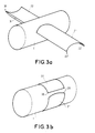
- Form 3a shows an example of application of blades according to the invention.
- a projectile 1, a submunition for example is provided with two blades 20, 30 according to the invention, a first blade 20 having a convex surface 21 and a concave surface 22, a second blade 30 having a convex surface 31 and a concave surface 32.
- the convex 21 and concave 32 surfaces have the same orientation, in order to obtain an asymmetric setting creating a torque, but the convex surfaces 21 and 31 could very well have the same orientation in another application.
- FIG. 3b illustrates an important advantage provided by the blades according to the invention.
- these blades are inactive and are wound and pressed against the projectile 1 thanks in particular to their flexibility. They are pressed so that the concave surfaces 22, 32 are in contact with the projectile 1, the convex surfaces 21, 31 being outward. Obviously, in this position, these surfaces are no longer convex or concave, these qualities being used relative to the deployed shape of the blades.
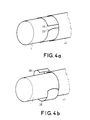
- the blades 20, 30 can be kept wound and pressed against the projectile 1 by holding means, for example by a ring or more simply by a cylindrical cover 41 surrounding the projectile 1 as illustrated in FIG.
- FIG. 4b illustrates the moment when the blades 20, 30 no longer undergo the action of the holding means, that is to say for example of the cover 41. Under the action of the elastic restoring force, they resume their straight shape with a concave profile defined by FIGS. 2a and 3a, a joint of the conventional type making it possible to complete deployment.
- the projectile 1 and the cover 41 are shown by way of example with a cylindrical shape with a circular base, however it is possible to press the blades 20, 30 on a projectile not having this shape and to hold them by a covering cover at least partially the projectile 1. It is preferable, however, that the projectile 1 does not have sharp asperities liable to damage the blades.
- the blades can be kept integral with the projectile 1 by conventional articulation means known to those skilled in the art.
- the blades 20, 30 integral with the projectile 1 of FIG. 3a can be oriented in a different way from that shown in this figure when they are deployed.
- FIG. 5 presents a plan view of a blade 51 according to the invention which can equip the projectile 1.
- This initially rectangular underwent two recesses at one of its widths so as to present a point 52.
- the attachment and the articulation of the blade 51 relative to the projectile 1 are effected at the point 52
- the clearances around the tip 52 allow the blade 51 to articulate around the projectile 1 of cylindrical shape for example.
- the blades have a notched shape when they are embedded on the projectile to allow their articulation.
- the shape of the previously described blades fitted to a projectile was that of a piece of concave ribbon, therefore this shape was substantially rectangular, with the recesses near to FIG. 5. This shape was adopted, because it is simple to produce. However, it is possible to give the blades according to the invention shapes other than rectangular.
- the blades according to the invention can for example have surfaces seen in plan in the shape of an oval, or petal of the aircraft propeller type. Likewise, elastic bending in a cross section of the projectile is not required. A folding around a propeller around the projectile can be interesting for example. Many shapes are acceptable, provided that the blades have the elastic, flexibility and stiffness properties described above and in particular that they have, for example, a concave shape when they are deployed. These blades can for example be made of a flexible metal, such as steel or other materials, for example composites, having an equivalent elastic modulus.
Landscapes
- Physics & Mathematics (AREA)
- Fluid Mechanics (AREA)
- Engineering & Computer Science (AREA)
- General Engineering & Computer Science (AREA)
- Toys (AREA)
Applications Claiming Priority (2)
| Application Number | Priority Date | Filing Date | Title |
|---|---|---|---|
| FR9115516 | 1991-12-13 | ||
| FR9115516A FR2685075B1 (fr) | 1991-12-13 | 1991-12-13 | Projectile equipe de pales elastiques. |
Publications (1)
| Publication Number | Publication Date |
|---|---|
| EP0546900A1 true EP0546900A1 (de) | 1993-06-16 |
Family
ID=9420039
Family Applications (1)
| Application Number | Title | Priority Date | Filing Date |
|---|---|---|---|
| EP92403282A Withdrawn EP0546900A1 (de) | 1991-12-13 | 1992-12-04 | Geschoss mit elastischen Flügeln |
Country Status (2)
| Country | Link |
|---|---|
| EP (1) | EP0546900A1 (de) |
| FR (1) | FR2685075B1 (de) |
Cited By (1)
| Publication number | Priority date | Publication date | Assignee | Title |
|---|---|---|---|---|
| CN111114261A (zh) * | 2020-03-19 | 2020-05-08 | 梁布和朝鲁 | 一种旋绕式伞骨 |
Citations (5)
| Publication number | Priority date | Publication date | Assignee | Title |
|---|---|---|---|---|
| FR1147642A (fr) * | 1956-04-11 | 1957-11-27 | Projectiles pour matériel d'infanterie ou d'artillerie | |
| DE8615207U1 (de) * | 1986-06-05 | 1988-03-03 | Rheinmetall GmbH, 4000 Düsseldorf | Leitwerk mit entfaltbaren Flügeln |
| DE8814130U1 (de) * | 1988-11-11 | 1990-04-05 | Diehl GmbH & Co, 8500 Nürnberg | Prüfgeschoß für Zünder bzw. für Baugruppen derartiger Zünder |
| EP0451123A1 (de) * | 1990-04-04 | 1991-10-09 | Ab Bofors | Submunition |
| US5067410A (en) * | 1990-12-21 | 1991-11-26 | The United States Of America As Represented By The Secretary Of The Army | Flexible wing |
-
1991
- 1991-12-13 FR FR9115516A patent/FR2685075B1/fr not_active Expired - Lifetime
-
1992
- 1992-12-04 EP EP92403282A patent/EP0546900A1/de not_active Withdrawn
Patent Citations (5)
| Publication number | Priority date | Publication date | Assignee | Title |
|---|---|---|---|---|
| FR1147642A (fr) * | 1956-04-11 | 1957-11-27 | Projectiles pour matériel d'infanterie ou d'artillerie | |
| DE8615207U1 (de) * | 1986-06-05 | 1988-03-03 | Rheinmetall GmbH, 4000 Düsseldorf | Leitwerk mit entfaltbaren Flügeln |
| DE8814130U1 (de) * | 1988-11-11 | 1990-04-05 | Diehl GmbH & Co, 8500 Nürnberg | Prüfgeschoß für Zünder bzw. für Baugruppen derartiger Zünder |
| EP0451123A1 (de) * | 1990-04-04 | 1991-10-09 | Ab Bofors | Submunition |
| US5067410A (en) * | 1990-12-21 | 1991-11-26 | The United States Of America As Represented By The Secretary Of The Army | Flexible wing |
Cited By (1)
| Publication number | Priority date | Publication date | Assignee | Title |
|---|---|---|---|---|
| CN111114261A (zh) * | 2020-03-19 | 2020-05-08 | 梁布和朝鲁 | 一种旋绕式伞骨 |
Also Published As
| Publication number | Publication date |
|---|---|
| FR2685075B1 (fr) | 1995-04-07 |
| FR2685075A1 (fr) | 1993-06-18 |
Similar Documents
| Publication | Publication Date | Title |
|---|---|---|
| EP2448814B1 (de) | Rumpfelement mit einem rumpfsegment und übergangsvorrichtung | |
| EP3433169B1 (de) | Luftfahrzeugrotor mit faltbaren und verstellbaren blättern | |
| EP2167381B1 (de) | Kabelträgerkette für die mobile nasenklappe einer flugzeugtragfläche | |
| FR2666786A1 (fr) | Fuselages perfectionnes d'aeronefs et de missiles. | |
| EP2259006B1 (de) | Öffnungs- und Verriegelungsvorrichtung für Munitionsleitwerk | |
| FR2902763A1 (fr) | Articulation auto-motorisee pour ensemble articule tel qu'un panneau solaire de satellite | |
| EP0870105B1 (de) | Ausfahrbare raketentriebwerkdüse | |
| EP0011582B1 (de) | Verbesserung an Systemen zum Aufrollen eines Segels | |
| EP3029412B1 (de) | Projektil und waffe zur aufnahme eines solchen projektils | |
| FR3095022A1 (fr) | Système de freinage ainsi que procédé et dispositif pour déployer un corps creux de forme allongée enroulé | |
| FR2600618A1 (fr) | Aile a deploiement multiple, et son application a un engin volant | |
| EP0546900A1 (de) | Geschoss mit elastischen Flügeln | |
| EP0626512A1 (de) | Raketendüse mit ausgezacktem Austrittkonus | |
| CH684549A5 (fr) | Aile galbée déployable pour engin volant. | |
| FR2892382A1 (fr) | Pale de giravion munie d'un volet orientable a l'aide d'au moins une rotule principale dont le premier arbre est solidaire de ladite pale. | |
| EP0275766B1 (de) | Bremsmechanismus für entfaltbare Flügel und Fernlenkgeschoss mit diesem Mechanismus | |
| FR2780819A1 (fr) | Reflecteur d'antenne elastiquement deformable pour engin spatial | |
| EP0775887B1 (de) | Haltevorrichtung für die Beutel einer explosiven Ladung | |
| EP4136357B1 (de) | Stossarme und wiederverwendbare halte- und freigabevorrichtung | |
| EP0802389B1 (de) | Flugkörper mit entfaltbarem Flügel | |
| EP0685059B1 (de) | Schlagbolzensicherung und verfahren zu seiner herstellung | |
| FR2716965A1 (fr) | Engin largable à stabilisation et freinage aérodynamique. | |
| EP2331429B1 (de) | Schutzelement für ein zu schützendes glied, insbesondere einen abgasschlauch | |
| EP3692324B1 (de) | Flügelsperrvorrichtung und geschoss mit einer solchen vorrichtung | |
| EP0653604A1 (de) | Entfaltungseinrichtung für Stabilisatorflügel eines Raketengeschosses |
Legal Events
| Date | Code | Title | Description |
|---|---|---|---|
| PUAI | Public reference made under article 153(3) epc to a published international application that has entered the european phase |
Free format text: ORIGINAL CODE: 0009012 |
|
| AK | Designated contracting states |
Kind code of ref document: A1 Designated state(s): DE SE |
|
| STAA | Information on the status of an ep patent application or granted ep patent |
Free format text: STATUS: THE APPLICATION IS DEEMED TO BE WITHDRAWN |
|
| 18D | Application deemed to be withdrawn |
Effective date: 19931217 |