EP0548011B2 - Schweissnahtabdeckung auf der Innenseite von Blechrohren - Google Patents
Schweissnahtabdeckung auf der Innenseite von Blechrohren Download PDFInfo
- Publication number
- EP0548011B2 EP0548011B2 EP92810961A EP92810961A EP0548011B2 EP 0548011 B2 EP0548011 B2 EP 0548011B2 EP 92810961 A EP92810961 A EP 92810961A EP 92810961 A EP92810961 A EP 92810961A EP 0548011 B2 EP0548011 B2 EP 0548011B2
- Authority
- EP
- European Patent Office
- Prior art keywords
- application
- hot
- arm
- metal tubes
- welding
- Prior art date
- Legal status (The legal status is an assumption and is not a legal conclusion. Google has not performed a legal analysis and makes no representation as to the accuracy of the status listed.)
- Expired - Lifetime
Links
Images


Classifications
-
- B—PERFORMING OPERATIONS; TRANSPORTING
- B23—MACHINE TOOLS; METAL-WORKING NOT OTHERWISE PROVIDED FOR
- B23K—SOLDERING OR UNSOLDERING; WELDING; CLADDING OR PLATING BY SOLDERING OR WELDING; CUTTING BY APPLYING HEAT LOCALLY, e.g. FLAME CUTTING; WORKING BY LASER BEAM
- B23K11/00—Resistance welding; Severing by resistance heating
- B23K11/06—Resistance welding; Severing by resistance heating using roller electrodes
- B23K11/061—Resistance welding; Severing by resistance heating using roller electrodes for welding rectilinear seams
- B23K11/062—Resistance welding; Severing by resistance heating using roller electrodes for welding rectilinear seams for welding longitudinal seams of tubes
- B23K11/063—Lap welding
-
- Y—GENERAL TAGGING OF NEW TECHNOLOGICAL DEVELOPMENTS; GENERAL TAGGING OF CROSS-SECTIONAL TECHNOLOGIES SPANNING OVER SEVERAL SECTIONS OF THE IPC; TECHNICAL SUBJECTS COVERED BY FORMER USPC CROSS-REFERENCE ART COLLECTIONS [XRACs] AND DIGESTS
- Y10—TECHNICAL SUBJECTS COVERED BY FORMER USPC
- Y10T—TECHNICAL SUBJECTS COVERED BY FORMER US CLASSIFICATION
- Y10T156/00—Adhesive bonding and miscellaneous chemical manufacture
- Y10T156/10—Methods of surface bonding and/or assembly therefor
- Y10T156/1002—Methods of surface bonding and/or assembly therefor with permanent bending or reshaping or surface deformation of self sustaining lamina
- Y10T156/1007—Running or continuous length work
- Y10T156/1008—Longitudinal bending
- Y10T156/1013—Longitudinal bending and edge-joining of one piece blank to form tube
Definitions
- the invention relates to a device according to the generic term of claim 1.
- the invention further relates to a method for operating the device and on an application of the method.
- Welding machines which have an "in line” order system, that a protective strip on the inner longitudinal weld of sheet metal pipes, especially of longitudinally welded sleeve and can jackets, applies. Basically, it is between the Spraying a paint and applying one Powder distinguished that on the spot an adhesive layer is fused.
- a varnish is applied depending on the Machine type, top or bottom, being the one to be treated Sheet metal tube usually on an application arm hanging, when applied in the lower Area, on the other hand, standing on a conveyor belt, transported in the longitudinal direction of the application arm becomes.
- the Paint without air with high pressure through pipes small diameter brought to the spray nozzle.
- the paint is also atomized in an air stream.
- the inner one Weld seam covered with a wet paint the dry layer is about 10 ⁇ m thick, but in Compared to a white interior paint porous.
- the tips of spot and grid welds not be covered by paint, because it drains away.
- US.A.3733670 describes a device for the production of a longitudinal weld seam large food container by the edges a sheet is placed on top of one another and welded with tin become.
- This welding device includes a cleaning brush and a spraying device for liquid tin by flame spraying.
- the containers are individually on a Roller conveyor moved forward. Applying one layer other than tin is neither mentioned nor indicated, in particular, is not from the supply and applying a hot melt mass.
- US, A 3077171 relates to a continuous device Apply a protective layer to cover the inside a longitudinal weld seam of sheet metal tubes on one Welding machine. It becomes a resinous material than plastic Protective layer applied.
- the material is fed as with all known devices in the feed direction the tubular body transported at the end face distance, by a belt or a conveyor pipe through which, tubular trained welding arm is performed.
- One with the Welding arm coaxial application arm carrying the tubular body is semi-cylindrical and shields the application device for the protective layer.
- the inventor has therefore set himself the task a device of the type mentioned and to create a process for their operation, which the use of hotmelts on simple. enable economical and effective manner. All unwanted diffusion processes with one filled goods, especially food be prevented.
- the tubular applicator arm is in in a manner known per se at one end connected to the welding arm of the welding machine and elsewhere freely movable in the axial direction preferably supported.
- This kind of order arm is referred to below as application tube.
- the hot melt mass introduced into the application tube is block-shaped, the blocks at most about the inner cross section of the application tube correspond. According to that in the The hotmelt blocks are generally round in cross-section mostly cylindrical. There are a large number of hot melts for the inventive Suitable for use, particularly interesting food-safe hotmelts, such as based on a polyester or an epoxy resin.
- the force for advancing is expedient and pressing the block-shaped hot melt mass generated via a plate-shaped insert, which in its outer dimensions the inner dimensions of the application tube.
- the hot melt blocks also called candles because of their shape, can so according to consumption are pushed forward by melting, if necessary, known rolling or rolling Aids can be applied. Blocks can be pushed with far less effort such as a corresponding granulate, which moreover has the disadvantage of being too small Has compactness.
- An insert with external thread which in one corresponding thread on the inside of the Application tube engages, must necessarily be round his.
- pneumatic or hydraulic means against it in addition to the preferred round inner cross-section other cross sections of the application tube can also be used, especially a rectangular or square.
- the device is the object of the invention solved that the block-shaped hot melt mass, counter to the direction of advance of the sheet metal tubes, passed through the application tube, in Area of the narrowing heater melted, through the inflow pipe into the application nozzle led and as a strip on the inside of the Longitudinal weld seam applied or sprayed on becomes.
- Special and further training embodiments are the subject of dependent claims.
- the block-shaped hotmelt mass in relation to the feed direction feed the sheet metal pipes from the front is the application of a hot melt protective strip on a longitudinal weld in a sheet metal tube helped to break through.
- This Process also leaves more complicated technical solutions open, which is a continuous or quasi-continuous operation regarding the introduction of hot melt blocks in the application tube.
- the application of the inner protective strip can in the same way up, down or in a side Position, this depends on the Location of the application nozzle, the arrangement of the can transport device and for those working "in line” Welding machines from the orientation of the inner welding roll on the application nozzle.
- the hot melt strip is applied mostly at the top, the sheet metal tubes hang on one smaller diameter welding arm, on the application tube, or on at least one overhead conveyor and are in the axial direction pushed on.
- the hotmelts used according to the invention preferably have a melting point in the range from 100-300 ° C, especially food-safe from 200 to 280 ° C.
- the heating jackets are controlled by sensors, program-controlled brought to an appropriate temperature.
- the width of the applied or sprayed Hot melt strip depends on the Weld seam, in practice it lies in the area from 3 to 12 mm.
- the applied hot melt strip becomes hard immediately, with preferred layer thicknesses from 20 to 150 ⁇ m, in particular 20 to 50 ⁇ m, cannot produce tips generated during welding press through, as is the case with the paint coating process the case is.
- One in the inflow pipe onto the melted hot melt mass acting pump supports and increases the through the drive element with the Use generated pressure. In particular, this can with a more viscous hot melt, when spraying and / or in the formation of overly long application pipes be the case.
- the pump Pressures of, for example, 5 to 50 Pa, in particular 10 to 35 Pa.
- the device according to the invention and the Processes for their operation have the industrial Advantage previously not achievable for hot melt masses, that the application nozzle is adjacent to the Welding roll can be attached. Therefore can the one hand from the welding roll to the Transferred heat can be used and on the other hand are the weld seams of the tubing still precisely aimed.
- a particularly advantageous application of the invention lies in the application a sterilization-proof hotmelt mass on the inside Longitudinal weld seam of a tin can jacket.
- One layer is said to be sterilization-proof, if they e.g. when heating during remains unchanged at about 130 ° C for about 1 h.
- the invention not only allows a hot melt coating with new systems, with little effort existing systems can be converted.
- the sheet metal tube 10 partially shown in FIG. 1 has a longitudinal weld 12, which on the Inside with a longitudinal hot-melt strip 14 is covered from a polyester.
- the face to face Sheet metal pipes not shown for clarity.
- On the welding arm 16 of a commercially available not shown welding machine is in Area of the end face 20 an inner welding roll 18 stored.
- the welding arm 16 has, for example a diameter of 60 mm, the slightly outstanding inner welding roller 18 such of 62 mm.
- This welding arm is special for welding sheet metal pipes of one diameter suitable from about 65 to 200 mm.
- the diameter of the sheet metal tubes can only be slightly, but also be a lot bigger than the one of the welding arm 16.
- Sheet metal pipes is a correspondingly adapted one Welding arm 16 can be used.
- the application tube 22 with the same longitudinal axis L is with fasteners 24 attached to the welding arm 16.
- the fastening means 24 are, for example Screws, rivets, an inner flange or one Welding.
- the shown in Figs. 4 and 5 Fasteners 24 have a bore 26 for Cable entries.
- the stand 30 with the expandable ball bearing rollers 28 is depending on the diameter of the sheet metal tubes with respect to Height adjustable, what with a double arrow 31 is indicated. Stand 30 and ball bearing rollers 28 can the respective sheet metal tube diameter be adjusted.
- the joined by the inner welding roll 18, Sheet metal tubes 10, not shown run in-line on the application tube 22, where they are from pushed on an endless conveyor belt 32 which of two pulleys 34, 36, one of which is the drive roller.
- the Conveyor belt 32 has a magnetic holder for the sheet metal tubes and a variable drive.
- the Transport device 32, 34, 36 can move upwards be folded away. With respect to the vertical can be symmetrical on both sides of the weld two transport devices 32, 34, 36 are also arranged his.
- the application tube 22 has a cover 38, which is flush on the outside and inside and about the top half of the application tube 22 extends. To remove the over a Part of the length of the application tube 22 extending Cover 38 will initially be the withdrawable funds with the conveyor belt 32 and the deflection rollers 34, 36 folded up, then screwing the Lid 38 released. Indicates the inner surface of the application tube also has an internal thread Cover 38 has a corresponding thread.
- the cover 38 When the cover 38 is raised, it can be block-shaped Hot melt mass 40, in the present case four about 20 cm long hot melt rolls of one diameter of about 50 mm, in the about 1.5 m long Application tube can be filled.
- a DC motor 44 is mounted in the area of the open end face 42 of the application tube 22 in the area of the open end face 42 of the application tube 22.
- a twist bracket 46 is also a cable guide for the connection cable 48 of the DC motor 44.
- One exerted by the DC motor 44 Torque is caused by the rotating insert 50 a thrust force in the forward direction V on the inserted hot melt blocks 40 and leads during melting to a feed with adjustable Hiring force.
- the DC motor 44 with the insert 50 be returned at high speed.
- the hot melt blocks 40 in one Melting zone 56 become pasty.
- Indoor 58 of the heater 54 the hot melt mass is complete liquefied and is by the DC motor 44 feeds exerted with the insert 50 and pressing force through an inflow pipe 60 to an exchangeable application nozzle 62 flow.
- the application nozzle protrudes through an opening 62 the outer jacket of the application tube 22 to the same extent as the inner welding roll 18 the outer jacket of the welding arm 16.
- the application nozzle 62 is replaceable attached to a nozzle holder 64. It is for application or for spraying the hot melt mass 40 in trained in a known manner.
- the width of the longitudinal weld seam 12 covering hotmelt strip 14 (FIG. 1) determines the length of the cross slot.
- the discharge opening the application nozzle 62 is corresponding the radius of the guided in the longitudinal direction L.
- Sheet metal tubes designed and therefore interchangeable.
- the inflow pipe 60 is exchangeable Filter cartridge 66 through a second heater 68 out, to which the nozzle holder 64 is attached is.
- the mini pump is powered by a DC motor 70 operated with a gear 72; which one via a drive wheel 74 and a toothed belt 76 acts on a pump wheel 78.
- the DC motor 70 of the mini pump via an opening 80 in the lower region of the application tube 22 ventilated and cooled. This opening 80 is also used to replace the application nozzle 62.
- the narrowing heater 54 in the inflow pipe 60 and in the nozzle attachment 64 is at least one sensor 82, 84, 86, 88 each.
- Hot melt mass 40 can be the application tube 22 coated with Teflon on the inside and / or at least be warmed up part of the length.
Landscapes
- Engineering & Computer Science (AREA)
- Mechanical Engineering (AREA)
- Coating Apparatus (AREA)
- Lining Or Joining Of Plastics Or The Like (AREA)
- Application Of Or Painting With Fluid Materials (AREA)
Description
- das Antriebsorgan mit dem Einsatz zurückgefahren und aus dem Auftragsrohr entfernt, ein langer oder mehrere kürzere Hotmelt-Blöcke eingesetzt und der Einsatz und das Eintriebsorgan wieder positioniert, oder
- ein innen und aussen flächenbündiger, sich über etwa den oberen Bereich des Umfangs erstreckender Deckel wird abgehoben, Hotmelt-Blöcke werden eingelegt und in Richtung des Schweissarms verschoben, und der Deckel wird wieder verschlossen. Selbstverständlich muss vorher der Einsatz zurückgefahren, die Dosentransporteinrichtung weggeklappt und die den Deckel blockierenden Blechrohre abgestreift werden.
- das meist etwa 1,1 - 2,0 m lange Auftragsrohr verlängert, und/oder
- eine dünnere Schicht aufgetragen wird.
- Fig. 1 einen teilweisen Querschnitt durch ein Blechrohr im Bereich der Längsschweissnaht.
- Fig. 2 eine teilweise aufgeschnittene Ansicht einer Vorrichtung zum kontinuierlichen Auftragen eines Hotmelt-Schutzstreifens,
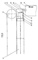
- Fig. 3 die Vorrichtung gemäss Fig. 2 im Bereich des Antriebsorgans für den Vorschub der blockförmigen Hotmelt-Masse,
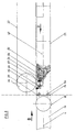
- Fig. 4 die Vorrichtung gemäss Fig. 2 im Bereich der Applikationsdüse, und
- Fig. 5 eine Variante von Fig. 4.
- keine Filterpatrone 66 und
- im Zuflussrohr 60 keine Minipumpe auf.
Claims (10)
- Schweissmaschine zum Herstellen von in Axialrichtung verschweissten Blechrohren (10) mit einer Vorrichtung zum kontinuierlichen Auftragen einer Schutzschicht (14) zum Abdecken der Innenseite der Längsschweissnaht (12) der in Axialrichtung (L) transportierten Blechrohre (10), welche Schweissmaschinea) eine auf einem Schweissarm (16) angeordnete innere Schweissrolle (18),b) einen coaxial und oberflächenbündig zum Schweissarm (18) verlaufenden, die Blechrohre (10) tragenden Auftragsarm (22), welcher rohrförmig ausgebildet ist,c) Mittel (32, 34, 36) zum Transport der Blechrohre (10), undd) eine Auftragseinrichtung für die Schutzschicht (14) umfasst,
dadurch gekennzeichnet, dasse) die Mittel (32,34,36) zum Transport der Blechrohre (10) im Bereich des Auftragsarms (22) wegklappbar und zum Transport stirnseitig aneinanderliegender Blechrohre (10) in Axialrichtung (L) vorgesehen sind,f) der Auftragsarm (22) als Arbeitsreservoir für blockförmige Hotmelt-Masse (40) ausgestaltet ist,g) im Auftragsarm (22) Mittel (44) zum Vorschieben und Andrücken der Hotmelt-Masse (40) in Richtung (V) des Schweissarms (16) mit einem vor- und rückwärts verschiebbaren Einsatz (50) angeordnet sind,h) eine die Hotmelt-Masse (40) führende Heizung (54) im Auftragsarm (22) sich in Vorschubrichtung (V) der Hotmelt-Masse (40) verengt, undi) im Auftragsarm (22) ein Zuflussrohr (60) für die Speisung einer benachbart des Schweissarms (16) als Auftragseinrichtung dienende, auswechselbare Applikationsdüse (62) angeordnet ist. - Schweissmaschine nach Anspruch 1, dadurch gekennzeichnet. dass zum Vorschieben und Anpressen der blockförmigen Hotmelt-Masse (40)der Einsatz (50) als elektromotorisch angetriebener Gewindenng mit aussenliegendem Gewinde (52) ausgebildet ist. und die Innenseite des Auftragsrohrs (22) ein entsprechendes Gewinde hat. oderder Einsatz (50) auf einer in der Längsachse (L) des Auftragsrohrs (22) liegenden, elektromotorisch angetriebenen Spindel läuft, wobei der/die Hotmelt-Block/Blöcke (40) eine entsprechende Bohrung hat/haben, oderder Einsatz (50) als von einem Aggregat betriebener Kolben pneumatisch ausgebildet ist.
- Schweissmaschine nach Anspruch 2, dadurch gekennzeichnet. dass der Einsatz (50) und das Antriebsorgan (44) auswechselbar oder entfernbar in das Auftragsrohr (22) eingesetzt sind.
- Schweissmaschine nach Anspruch 1 oder 2, dadurch gekennzeichnet, dass ein abhebbar befestigter, sich über etwa die obere Hälfte des Umfangs eines Teils des Auftragsrohrs (22) erstreckender Deckel (38) angeordnet ist, welcher innen vollständig, aussen wenigstens im oberen Bereich flächenbündig schliesst.
- Schweissmaschine nach einem der Ansprüche 1 bis 4, dadurch gekennzeichnet, dass um das Zuflussrohr (60) wenigstens eine weitere Heizung (68) angeordnet ist, vorzugsweise auch in Form einer Heizmanschette, eines Heizdrahtes oder Heizbandes.
- Schweissmaschine nach einem der Ansprüche 1 bis 5, dadurch gekennzeichnet, dass im Zuflussrohr (60) zur Applikationsdüse (62) eine Pumpe für die flüssige Hotmeit-Masse (40) und vorzugsweise eine auswechselbare Filterpatrone (66) eingebaut ist.
- Verfahren zum Betrieb der Schweissmaschine nach einem der Ansprüche 1 bis 6,
dadurch gekennzeichnet, dass
die blockförmige Hotmelt-Masse (40), der Vorschubrichtung (B) der Blechrohre (10) entgegenlaufend, in Richtung (V) durch das Auftragsrohr (22) geführt, im Bereich der sich verengenden Heizung (54) geschmolzen, durch das Zuflussrohr (60) in die Applikationsdüse (62) geführt und als Hotmelt-Streifen (14) auf die Innenseite der Längsschweissnaht (12) von Blechrohren (10) aufgetragen oder aufgespritzt wird. - Verfahren nach Anspruch 7, dadurch gekennzeichnet. dass die Hotmelt-Masse (40) im Bereich der sich verengenden Heizung (54) bei einer Temperatur von 100-300°C. vorzugsweise 200 bis 280°C, geschmolzen, im Zuflussrohr (60) auf dieser Temperatur gehalten, und mit einem Durchsatz von 0.2 bis 1.5 kg/h als 20 bis 150 µm, vorzugsweise 20 bis 50 µm dicker, 3 bis 12 mm breiter Hotmelt-Streifen (14) aufgetragen wird.
- Verfahren nach Anspruch 7 oder 8. dadurch gekennzeichnet. dass die verflüssigte Hotmelt-Masse (40) mit einer in das Zuflussrohr (60) eingebauten Pumpe mit einem Druck von 5 bis 50 Pa, vorzugsweise 10 bis 35 Pa, zur Applikationsdüse (62) geleitet wird.
- Anwendung des Verfahrens nach einem der Ansprüche 7 bis 9 zum Auftragen eines sterilisationsfesten Hotmelt-Streifens (14) auf die innere Längsschweissnaht (12) eines Weissblechdosenmantels (10).
Applications Claiming Priority (3)
| Application Number | Priority Date | Filing Date | Title |
|---|---|---|---|
| CH3735/91 | 1991-12-17 | ||
| CH3735/91A CH684524A5 (de) | 1991-12-17 | 1991-12-17 | Schweissnahtabdeckung auf der Innenseite von Blechrohren. |
| CH373591 | 1991-12-17 |
Publications (3)
| Publication Number | Publication Date |
|---|---|
| EP0548011A1 EP0548011A1 (de) | 1993-06-23 |
| EP0548011B1 EP0548011B1 (de) | 1995-05-17 |
| EP0548011B2 true EP0548011B2 (de) | 2001-12-05 |
Family
ID=4262380
Family Applications (1)
| Application Number | Title | Priority Date | Filing Date |
|---|---|---|---|
| EP92810961A Expired - Lifetime EP0548011B2 (de) | 1991-12-17 | 1992-12-07 | Schweissnahtabdeckung auf der Innenseite von Blechrohren |
Country Status (5)
| Country | Link |
|---|---|
| US (1) | US5296078A (de) |
| EP (1) | EP0548011B2 (de) |
| CH (1) | CH684524A5 (de) |
| DE (1) | DE59202243D1 (de) |
| ES (1) | ES2075673T5 (de) |
Families Citing this family (6)
| Publication number | Priority date | Publication date | Assignee | Title |
|---|---|---|---|---|
| EP0591107A1 (de) * | 1992-09-28 | 1994-04-06 | Balti Ag | Schweissnahtabdeckung von Blechrohren |
| DE4325749C1 (de) * | 1993-07-31 | 1995-02-16 | Zueblin Ag | Schweißvorrichtung zum Verschweißen eines Schweißprofils in einer Schweißnut |
| US6146695A (en) * | 1996-03-06 | 2000-11-14 | Frey; Ernst M. | Internal weld protection of sheet metal pipes |
| US5925264A (en) * | 1997-04-15 | 1999-07-20 | Ball Corporation | Method and apparatus for detecting surface contamination in a weld area |
| CN106584721B (zh) * | 2016-12-22 | 2019-08-13 | 苏州振瑞昌材料科技有限公司 | 一种加热固化装置 |
| CN115956137A (zh) * | 2020-09-03 | 2023-04-11 | 住友重机械工业株式会社 | 处理装置、处理方法、金属管材料及其制造方法 |
Family Cites Families (13)
| Publication number | Priority date | Publication date | Assignee | Title |
|---|---|---|---|---|
| US3077171A (en) * | 1959-04-09 | 1963-02-12 | American Can Co | Method of forming the side seam of a can body |
| US3118406A (en) * | 1959-09-09 | 1964-01-21 | American Mach & Foundry | Apparatus for welding edges of tubes |
| US3526027A (en) * | 1967-05-29 | 1970-09-01 | Continental Can Co | Apparatus for coating side seam areas of containers |
| US3733670A (en) * | 1972-06-29 | 1973-05-22 | Rheem Mfg Co | Apparatus for making food containers |
| JPS5144751Y2 (de) * | 1973-01-25 | 1976-10-29 | ||
| US4032046A (en) * | 1976-11-01 | 1977-06-28 | Usm Corporation | Apparatus for feeding glue to a hot melt glue dispensing appliance |
| US4180011A (en) * | 1977-09-12 | 1979-12-25 | The Sherwin-Williams Company | Apparatus for spraying a coating on the inside surfaces of longitudinal seams on can bodies |
| US4353326A (en) * | 1981-03-20 | 1982-10-12 | Nordson Corporation | Apparatus for the stripping of the inside seam of a can body moving at a high speed |
| JPS5978786A (ja) * | 1982-10-29 | 1984-05-07 | Toyota Motor Corp | シ−ム溶接機 |
| DE3574941D1 (de) * | 1984-07-06 | 1990-02-01 | Ribnitz Peter | Verfahren zur innenbeschichtung von hohlkoerpern und anlage zur ausfuehrung des verfahrens. |
| US4615296A (en) * | 1984-08-15 | 1986-10-07 | Nordson Corporation | Continuous coating system for discrete articles |
| DE8613376U1 (de) * | 1986-05-16 | 1986-06-26 | Ursprung, Reinhard, 8088 Eching | Heißkleberpistole mit mechanischem Vorschub |
| JPH0624659B2 (ja) * | 1986-06-04 | 1994-04-06 | 北海製罐株式会社 | 缶胴体の塗装方法および塗装装置 |
-
1991
- 1991-12-17 CH CH3735/91A patent/CH684524A5/de not_active IP Right Cessation
-
1992
- 1992-12-07 EP EP92810961A patent/EP0548011B2/de not_active Expired - Lifetime
- 1992-12-07 DE DE59202243T patent/DE59202243D1/de not_active Expired - Fee Related
- 1992-12-07 ES ES92810961T patent/ES2075673T5/es not_active Expired - Lifetime
- 1992-12-14 US US07/992,265 patent/US5296078A/en not_active Expired - Lifetime
Also Published As
| Publication number | Publication date |
|---|---|
| ES2075673T3 (es) | 1995-10-01 |
| EP0548011A1 (de) | 1993-06-23 |
| EP0548011B1 (de) | 1995-05-17 |
| ES2075673T5 (es) | 2002-06-16 |
| DE59202243D1 (de) | 1995-06-22 |
| CH684524A5 (de) | 1994-10-14 |
| US5296078A (en) | 1994-03-22 |
Similar Documents
| Publication | Publication Date | Title |
|---|---|---|
| DE1750580C3 (de) | Vorrichtung zum Aufbringen einer Thermoplast-Sperrschicht auf Teile der Gewinde von Kopfschrauben | |
| EP2809474B1 (de) | Vorrichtung zum reibauftragsbeschichten einer oberfläche eines werkstücks | |
| CH656079A5 (de) | Verfahren zum verformen der ruempfe von blechgebinden und vorrichtung zur durchfuehrung des verfahrens. | |
| DE2728741C2 (de) | ||
| DE602004008448T2 (de) | Die materialanwendung von stäbchenverpackungen betreffende verbesserungen | |
| DE3932312C2 (de) | ||
| EP0603456B1 (de) | Verfahren, Vorrichtung und Beschichtungsmaterial zum Dosennahtbeschichten | |
| EP1420903A2 (de) | Verfahren und vorrichtung zum haspeln von dünnem metallband, insbesondere von warm- oder kaltgewalztem dünnen stahlband | |
| EP0548011B1 (de) | Schweissnahtabdeckung auf der Innenseite von Blechrohren | |
| DE4117555C1 (de) | ||
| DE1632139B2 (de) | Verfahren zum kraeuseln synthetischer wursthuellen | |
| EP0115012B1 (de) | Verfahren zum Herstellen von Gewinden und Einrichtung zur Durchführung des Verfahrens | |
| DE2426072A1 (de) | Automatische bohr- und boerdelvorrichtung | |
| EP0885085B1 (de) | Innenseitiger schweissnahtschutz von blechrohren | |
| EP0591107A1 (de) | Schweissnahtabdeckung von Blechrohren | |
| WO2000043569A1 (de) | Verfahren zum abdecken von verletzten schutzschichtstellen, vorrichtung zur durchführung des verfahrens und ein transportsystem | |
| CH698495B1 (de) | Vorrichtung zur Bereitstellung eines fliessfähigen Mediums. | |
| EP2527289A1 (de) | Vorrichtung und Verfahren zum Anbringen eines Schraubverschlusses | |
| DE2820750A1 (de) | Verfahren und vorrichtung zum herstellen eines mit einer verstaerkungswendel versehenen kunststoffschlauchs | |
| EP0603702B1 (de) | Vorrichtung zur Herstellung von Granulat | |
| DE2543117C2 (de) | Vorrichtung zur Beschichtung eines bestimmten Bereiches von zylindrisch geformten Werkstücken mit einem viskosen Medium | |
| EP0603701B1 (de) | Vorrichtung zum streifen- oder tropfenförmigen Ausbringen fliessfähiger Massen | |
| DE2523520A1 (de) | Kontinuierlich arbeitende versiegelungsmaschine fuer rundfoermige schachteln | |
| EP1253980A1 (de) | Bodenlackierung von getränkedosen | |
| DE2939156C2 (de) | Verfahren und Vorrichtung zum Anlegen einer Stahlblech-Manschette an ein Stahlrohr |
Legal Events
| Date | Code | Title | Description |
|---|---|---|---|
| PUAI | Public reference made under article 153(3) epc to a published international application that has entered the european phase |
Free format text: ORIGINAL CODE: 0009012 |
|
| AK | Designated contracting states |
Kind code of ref document: A1 Designated state(s): CH DE ES FR GB IT LI NL |
|
| 17P | Request for examination filed |
Effective date: 19931113 |
|
| 17Q | First examination report despatched |
Effective date: 19940316 |
|
| GRAA | (expected) grant |
Free format text: ORIGINAL CODE: 0009210 |
|
| AK | Designated contracting states |
Kind code of ref document: B1 Designated state(s): CH DE ES FR GB IT LI NL |
|
| PG25 | Lapsed in a contracting state [announced via postgrant information from national office to epo] |
Ref country code: NL Free format text: LAPSE BECAUSE OF FAILURE TO SUBMIT A TRANSLATION OF THE DESCRIPTION OR TO PAY THE FEE WITHIN THE PRESCRIBED TIME-LIMIT Effective date: 19950517 Ref country code: GB Free format text: LAPSE BECAUSE OF FAILURE TO SUBMIT A TRANSLATION OF THE DESCRIPTION OR TO PAY THE FEE WITHIN THE PRESCRIBED TIME-LIMIT Effective date: 19950517 |
|
| ITF | It: translation for a ep patent filed | ||
| REF | Corresponds to: |
Ref document number: 59202243 Country of ref document: DE Date of ref document: 19950622 |
|
| GBT | Gb: translation of ep patent filed (gb section 77(6)(a)/1977) |
Effective date: 19950612 |
|
| ET | Fr: translation filed | ||
| REG | Reference to a national code |
Ref country code: ES Ref legal event code: FG2A Ref document number: 2075673 Country of ref document: ES Kind code of ref document: T3 |
|
| PLBQ | Unpublished change to opponent data |
Free format text: ORIGINAL CODE: EPIDOS OPPO |
|
| PLBI | Opposition filed |
Free format text: ORIGINAL CODE: 0009260 |
|
| PLBF | Reply of patent proprietor to notice(s) of opposition |
Free format text: ORIGINAL CODE: EPIDOS OBSO |
|
| 26 | Opposition filed |
Opponent name: SOUDRONIC AG Effective date: 19960219 |
|
| NLR1 | Nl: opposition has been filed with the epo |
Opponent name: SOUDRONIC AG |
|
| PLBF | Reply of patent proprietor to notice(s) of opposition |
Free format text: ORIGINAL CODE: EPIDOS OBSO |
|
| PLAW | Interlocutory decision in opposition |
Free format text: ORIGINAL CODE: EPIDOS IDOP |
|
| APAC | Appeal dossier modified |
Free format text: ORIGINAL CODE: EPIDOS NOAPO |
|
| APAE | Appeal reference modified |
Free format text: ORIGINAL CODE: EPIDOS REFNO |
|
| APAE | Appeal reference modified |
Free format text: ORIGINAL CODE: EPIDOS REFNO |
|
| PGFP | Annual fee paid to national office [announced via postgrant information from national office to epo] |
Ref country code: GB Payment date: 20001115 Year of fee payment: 9 |
|
| PGFP | Annual fee paid to national office [announced via postgrant information from national office to epo] |
Ref country code: NL Payment date: 20001121 Year of fee payment: 9 |
|
| APAC | Appeal dossier modified |
Free format text: ORIGINAL CODE: EPIDOS NOAPO |
|
| PLAW | Interlocutory decision in opposition |
Free format text: ORIGINAL CODE: EPIDOS IDOP |
|
| PUAH | Patent maintained in amended form |
Free format text: ORIGINAL CODE: 0009272 |
|
| 27A | Patent maintained in amended form |
Effective date: 20011205 |
|
| AK | Designated contracting states |
Kind code of ref document: B2 Designated state(s): CH DE ES FR GB IT LI NL |
|
| REG | Reference to a national code |
Ref country code: CH Ref legal event code: AEN Free format text: AUFRECHTERHALTUNG DES PATENTES IN GEAENDERTER FORM |
|
| REG | Reference to a national code |
Ref country code: GB Ref legal event code: IF02 |
|
| NLR2 | Nl: decision of opposition | ||
| NLV1 | Nl: lapsed or annulled due to failure to fulfill the requirements of art. 29p and 29m of the patents act | ||
| ET3 | Fr: translation filed ** decision concerning opposition | ||
| GBV | Gb: ep patent (uk) treated as always having been void in accordance with gb section 77(7)/1977 [no translation filed] |
Effective date: 19950517 |
|
| REG | Reference to a national code |
Ref country code: ES Ref legal event code: DC2A Kind code of ref document: T5 Effective date: 20020222 |
|
| APAH | Appeal reference modified |
Free format text: ORIGINAL CODE: EPIDOSCREFNO |
|
| PGFP | Annual fee paid to national office [announced via postgrant information from national office to epo] |
Ref country code: CH Payment date: 20051122 Year of fee payment: 14 |
|
| PGFP | Annual fee paid to national office [announced via postgrant information from national office to epo] |
Ref country code: DE Payment date: 20051212 Year of fee payment: 14 |
|
| PGFP | Annual fee paid to national office [announced via postgrant information from national office to epo] |
Ref country code: ES Payment date: 20051215 Year of fee payment: 14 |
|
| PGFP | Annual fee paid to national office [announced via postgrant information from national office to epo] |
Ref country code: FR Payment date: 20051219 Year of fee payment: 14 |
|
| PG25 | Lapsed in a contracting state [announced via postgrant information from national office to epo] |
Ref country code: LI Free format text: LAPSE BECAUSE OF NON-PAYMENT OF DUE FEES Effective date: 20061231 Ref country code: CH Free format text: LAPSE BECAUSE OF NON-PAYMENT OF DUE FEES Effective date: 20061231 |
|
| PGFP | Annual fee paid to national office [announced via postgrant information from national office to epo] |
Ref country code: IT Payment date: 20061231 Year of fee payment: 15 |
|
| REG | Reference to a national code |
Ref country code: CH Ref legal event code: PFA Owner name: ERNST M. FREY Free format text: ERNST M. FREY#LAUENEN 680A#3655 SIGRISWIL (CH) -TRANSFER TO- ERNST M. FREY#LAUENEN 680A#3655 SIGRISWIL (CH) |
|
| PG25 | Lapsed in a contracting state [announced via postgrant information from national office to epo] |
Ref country code: DE Free format text: LAPSE BECAUSE OF NON-PAYMENT OF DUE FEES Effective date: 20070703 |
|
| REG | Reference to a national code |
Ref country code: CH Ref legal event code: PL |
|
| REG | Reference to a national code |
Ref country code: FR Ref legal event code: ST Effective date: 20070831 |
|
| REG | Reference to a national code |
Ref country code: ES Ref legal event code: FD2A Effective date: 20061209 |
|
| PG25 | Lapsed in a contracting state [announced via postgrant information from national office to epo] |
Ref country code: FR Free format text: LAPSE BECAUSE OF NON-PAYMENT OF DUE FEES Effective date: 20070102 Ref country code: ES Free format text: LAPSE BECAUSE OF NON-PAYMENT OF DUE FEES Effective date: 20061209 |
|
| PG25 | Lapsed in a contracting state [announced via postgrant information from national office to epo] |
Ref country code: IT Free format text: LAPSE BECAUSE OF NON-PAYMENT OF DUE FEES Effective date: 20071207 |