EP0885085B1 - Innenseitiger schweissnahtschutz von blechrohren - Google Patents
Innenseitiger schweissnahtschutz von blechrohren Download PDFInfo
- Publication number
- EP0885085B1 EP0885085B1 EP97903200A EP97903200A EP0885085B1 EP 0885085 B1 EP0885085 B1 EP 0885085B1 EP 97903200 A EP97903200 A EP 97903200A EP 97903200 A EP97903200 A EP 97903200A EP 0885085 B1 EP0885085 B1 EP 0885085B1
- Authority
- EP
- European Patent Office
- Prior art keywords
- weld seam
- application
- arm
- application nozzle
- protective film
- Prior art date
- Legal status (The legal status is an assumption and is not a legal conclusion. Google has not performed a legal analysis and makes no representation as to the accuracy of the status listed.)
- Expired - Lifetime
Links
- 239000002184 metal Substances 0.000 title claims description 26
- 238000002844 melting Methods 0.000 claims description 29
- 230000008018 melting Effects 0.000 claims description 29
- 230000001681 protective effect Effects 0.000 claims description 27
- 238000003466 welding Methods 0.000 claims description 21
- 238000000034 method Methods 0.000 claims description 16
- 239000012943 hotmelt Substances 0.000 claims description 11
- 239000004033 plastic Substances 0.000 claims description 10
- 229920003023 plastic Polymers 0.000 claims description 10
- 238000010438 heat treatment Methods 0.000 claims description 7
- 239000007788 liquid Substances 0.000 claims description 3
- 239000011324 bead Substances 0.000 claims description 2
- 239000000155 melt Substances 0.000 claims description 2
- 229920000728 polyester Polymers 0.000 claims description 2
- 239000004814 polyurethane Substances 0.000 claims description 2
- 229920002635 polyurethane Polymers 0.000 claims description 2
- 239000012815 thermoplastic material Substances 0.000 claims 5
- 239000008187 granular material Substances 0.000 claims 1
- 239000000463 material Substances 0.000 description 15
- 229920001169 thermoplastic Polymers 0.000 description 12
- 239000004416 thermosoftening plastic Substances 0.000 description 7
- 239000000725 suspension Substances 0.000 description 5
- ATJFFYVFTNAWJD-UHFFFAOYSA-N Tin Chemical compound [Sn] ATJFFYVFTNAWJD-UHFFFAOYSA-N 0.000 description 3
- 230000001419 dependent effect Effects 0.000 description 3
- 235000013305 food Nutrition 0.000 description 3
- 239000011241 protective layer Substances 0.000 description 3
- 239000000523 sample Substances 0.000 description 3
- 239000011248 coating agent Substances 0.000 description 2
- 238000000576 coating method Methods 0.000 description 2
- 239000003822 epoxy resin Substances 0.000 description 2
- 229920000647 polyepoxide Polymers 0.000 description 2
- 125000006850 spacer group Chemical group 0.000 description 2
- 230000008719 thickening Effects 0.000 description 2
- 229910000831 Steel Inorganic materials 0.000 description 1
- 238000005299 abrasion Methods 0.000 description 1
- 239000000853 adhesive Substances 0.000 description 1
- 230000001070 adhesive effect Effects 0.000 description 1
- 239000000919 ceramic Substances 0.000 description 1
- 230000001143 conditioned effect Effects 0.000 description 1
- 238000005520 cutting process Methods 0.000 description 1
- 238000010586 diagram Methods 0.000 description 1
- 238000006073 displacement reaction Methods 0.000 description 1
- 238000001035 drying Methods 0.000 description 1
- 230000008030 elimination Effects 0.000 description 1
- 238000003379 elimination reaction Methods 0.000 description 1
- LNEPOXFFQSENCJ-UHFFFAOYSA-N haloperidol Chemical compound C1CC(O)(C=2C=CC(Cl)=CC=2)CCN1CCCC(=O)C1=CC=C(F)C=C1 LNEPOXFFQSENCJ-UHFFFAOYSA-N 0.000 description 1
- 238000000265 homogenisation Methods 0.000 description 1
- 230000001939 inductive effect Effects 0.000 description 1
- 239000010410 layer Substances 0.000 description 1
- 238000004519 manufacturing process Methods 0.000 description 1
- 235000011837 pasties Nutrition 0.000 description 1
- 239000000843 powder Substances 0.000 description 1
- 230000002787 reinforcement Effects 0.000 description 1
- 239000007787 solid Substances 0.000 description 1
- 239000010959 steel Substances 0.000 description 1
- 239000005028 tinplate Substances 0.000 description 1
- 238000002604 ultrasonography Methods 0.000 description 1
- 238000011144 upstream manufacturing Methods 0.000 description 1
- 239000002966 varnish Substances 0.000 description 1
Images


Classifications
-
- B—PERFORMING OPERATIONS; TRANSPORTING
- B23—MACHINE TOOLS; METAL-WORKING NOT OTHERWISE PROVIDED FOR
- B23K—SOLDERING OR UNSOLDERING; WELDING; CLADDING OR PLATING BY SOLDERING OR WELDING; CUTTING BY APPLYING HEAT LOCALLY, e.g. FLAME CUTTING; WORKING BY LASER BEAM
- B23K11/00—Resistance welding; Severing by resistance heating
- B23K11/06—Resistance welding; Severing by resistance heating using roller electrodes
- B23K11/061—Resistance welding; Severing by resistance heating using roller electrodes for welding rectilinear seams
- B23K11/062—Resistance welding; Severing by resistance heating using roller electrodes for welding rectilinear seams for welding longitudinal seams of tubes
- B23K11/063—Lap welding
Definitions
- the invention relates to a method for application a continuous protective film made of a thermoplastic Plastic on the inside of the longitudinal weld of sheet metal pipes, which lie face to face over each other the welding arm of a welding machine and a subsequent one Order arm are performed, the thermoplastic Plastic melted continuously and by means of an application nozzle at least over the entire width of the inner weld seam is applied.
- the invention further relates to a device for performing the method.
- Welding machines which have an "in-line" built-on Application system for a thermoplastic have a protective film on the longitudinal weld of sheet metal pipes, especially of longitudinally welded rifle and can coats. Basically, it will differentiate between applying a varnish and a powder, which cover in place to form a seam Layer to be processed.
- a protective film is applied above or below, the sheet metal pipe to be treated at Apply the protective film in the upper area to an application arm hanging, however, when applying in the lower area standing on a conveyor belt, in the longitudinal direction of the application arm is transported.
- Tin cans Especially for used in the food industry Tin cans is a clean, sterilization-proof inner cover the weld seam with an uninterrupted Protective film of paramount importance. Food safety further conditioned that the protective layer also hard mechanical Processing, such as attaching beads or the Flare, withstand.
- the application of sterilization-proof "Hotmelts", like thermoplastic adhesives made of plastic for short has so far failed because it technical means not adapted to the circumstances could be applied and the mechanical could not withstand stress.
- EP, A1 0591107 describes a process for continuous Apply protective layers to cover a longitudinal weld of sheet metal pipes.
- a hot melt mass is called flexible hotmelt thread continuously through the welding arm guided by a welding machine and towards the inside the longitudinal weld seam of the sheet metal tubes is deflected.
- the hotmelt thread is turned on by an application device Sheet metal tube pressed, melted and homogeneous across the width the longitudinal weld seam distributed.
- Simultaneously with the inner one can also have an outer protective layer on the longitudinal weld be applied, which is an elimination of Kilns or drying ovens allowed.
- the inventor has set himself the task of a method and a device of the type described in the introduction create which in industrial operation a problem-free, economical application of the continuous protective film ensure on the inner longitudinal weld.
- the continuous protective film should also be in Area of weld seam fluctuating curvature from successive Tubular bodies constant in terms of thickness and shape stay.
- the protective film should be adjustable across the width can be made thick.
- the object is achieved according to the invention solved in that the continuously fed thermoplastic Plastic preheated in the area of the application arm, melted and with homogeneous liquefaction to Order nozzle directed, the nozzle opening with adjustable, constant distance between the inside of the longitudinal weld the sheet metal pipes tracked, and the liquid plastic is applied in doses.
- the procedure are subject to dependent Claims.
- thermoplastic also called “hot melt” are primarily polyester, which are proportionate expensive, but resistant and above all food-safe are.
- hot melt are primarily polyester, which are proportionate expensive, but resistant and above all food-safe are.
- non-food-safe industrial cans can also use polyurethanes or in special cases even curable epoxy resins can be used.
- the thermoplastic Plastic in the form of a thread through the welding arm in the Order arm managed initially in a preheating zone on one Temperature of preferably about half the melting temperature preheated and then into a liquefaction zone a channel running in the same direction and melted there.
- the thread pushed into this channel is solid for the time being and melts continuously when it is pushed in again.
- the molten plastic preferably flows along of the inserted thread and can be inserted into another are diverted to the duct leading to the application nozzle.
- the channel and nozzle outlet opening are preferably dimensioned in this way and matched to the feed of the plastic thread, that the molten plastic flows out in a metered manner, but no pressure builds up in the melting apparatus can.
- plastic thread or "hot melt thread” includes also wires, cords and the like in comparison to the cross section long crowds.
- the preheating zone includes the advantage that when parking no heat flow back and the plastic drawer outside the apparatus can melt.
- a preheating zone for example, the plastic thread heated to 140 to 160 ° C and through a sealed opening into the channel of the liquefaction zone, where the Temperature depending on the material to a range of, for example about 220 to 280 ° C is increased.
- the preheating zone remains when the melting apparatus is switched on Expediently cold for the time being, this will only take about 10 minutes switched on after the heating cartridge to liquefy.
- thermoplastic not only in thread form, but also in other suitable ones Form added, for example in granular form or Candle shape according to EP, A1 0548 011 (and which is considered the closest prior art), melted and homogeneous liquefied to the application nozzle.
- a Melting device Means for tracking the outlet opening the application nozzle in an adjustable, regular Distance from the inside of the weld seam.
- the preheating with the preheating zone and the melting device with the liquefaction zone are preferably immediate arranged one after the other.
- the present Invention with simple means allowed a continuous Protective film made of a thermoplastic on the inside of the longitudinal weld seam of sheet metal pipes to apply, which is inevitable regardless of when welding resulting deformations always exactly the same is thick. Tear off the film or thickened transversely Positions are no longer possible, which is particularly the case with food safe tinplate tubes essential is. Melting and homogeneous liquefaction continue of the thermoplastic on simple and safe way solved before entering the application nozzle.
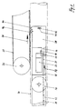
- Hotmelt thread 28 runs through a pair of rollers 30, which as Guidance and material feed for the thread 28 is used. At least one of the two rollers 30 is driven, according to FIG. 1 the upper roller 30 with an electric motor 32.
- the thread with a diameter in the range of about 2 to 4 mm indicated by the arrow 34 conveying direction over a Preheater 36 pushed into a melting apparatus 38.
- the melting apparatus 38 as a whole is around the suspension 40 pivotable.
- An elongated hole limiting this pivoting movement 42 is of a suspension 43 for the melting apparatus 38 penetrated.
- An application nozzle is on the device frame of the melting apparatus 38 44 for applying the protective film 20 (Fig. 8) and a trailing roller 46 attached as a spacer.
- the trailing roller 46 projects over the application nozzle 44 of the protective film 20 (FIG. 8th).
- Fig. 2 is the pivotable suspension of the melting apparatus 38 shown as a whole.
- One on the suspension 43 supported spring 48 presses the melting apparatus 38 with the Trailing roller 46 on the longitudinal weld 16 one Tin tube 10.
- the application nozzle 44 or its outflow opening has a constant distance from the Weld seam 16.
- the geometric shape of the sheet metal tubes is never exactly cylindrical, always arise during the welding process Deformations, curvatures and the like.
- the pressed-on trailing roller 46 can follow these deformations by the whole Melting apparatus 38 pivots about the suspension 40.
- the Spring 48 is therefore able to lift the melting apparatus 38 and to press.
- the distance between the application nozzle 44 and the longitudinal one As mentioned, the weld seam always remains constant.
- the material flow 48 is in the area of the melting apparatus 38 shown and the heating cartridges used 50, 52 in the area of the preheating zone 36 and a liquefaction zone 54 shown.
- the thread 28 made of a thermoplastic Plastic or hot melt is in the direction of the arrow pushed through the preheating zone 36, where it heated to about 150 ° C. becomes.
- the preheated thread passes through a sealed Opening into a melting channel 58 and is through flowing back, molten application material encountered. The further the thread 28 is pushed into the melting channel becomes, the more it softens, becomes pasty and finally liquid. This is indicated by the thread 28 for the time being with longer, then with shorter strokes and finally is drawn with dots.
- the melted thread 28 is further melted Material along the thread inserted into one here encountered overhead homogenization channel 60 where a homogeneous liquefaction of the order material takes place.
- the homogeneously liquefied application material arrives via an application channel 62 to the application nozzle 44, one Wide slot nozzle with reference to the supply of order material, i.e. the feed of the hot melt thread 28, large Outflow opening, which builds up pressure in the melting apparatus 38 prevented.
- This outflow opening of the application nozzle 44 is arranged less high than the distance a the follower roller 46.
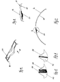
- the outflow opening 64 of an application nozzle 44 is a slot die, shown.
- This spout 64 is essentially rectangular.
- the two opposite Longitudinal walls of the application nozzle 44 are in the middle area deepened, in other words, the material which points away from the outlet opening 64 Removed in the direction of the thickening side walls.
- the protective film 20 In the middle area is the protective film 20 thicker than in the two marginal areas.
- the recess in the longitudinal walls of the nozzle can in principle be of any shape.
- the reinforcement of the Protective film in the middle area is the bigger, the more Material of the side walls is removed.
- the area of the outflow opening 64 is an application nozzle 44 indicated in section.
- the cutting plane lies in the longitudinal direction of the outflow opening 64.
- the wide material flow of liquefied thermoplastic in Direction of the outflow opening 64 prevents, as already mentioned, a pressure build-up in the melting apparatus (38 in Fig. 3) and allows covering the weld seam all over Width.
- Fig. 6 shows this application nozzle in side section, the material flow 66 has only a small thickness here, for example of 1 mm.
Landscapes
- Engineering & Computer Science (AREA)
- Mechanical Engineering (AREA)
- Lining Or Joining Of Plastics Or The Like (AREA)
Description
- Eine Nachlaufrolle und eine Auftragsdüse sind auf einem schwenkbaren Arm montiert. Die Nachlaufrolle rollt auf der durchlaufenden Innenseite der Schweissnaht der Blechrohre. Der vorhergehende Schweissvorgang hat zur Folge, dass die Blechrohre im Bereich der Längsschweissnaht verschieden stark gekrümmt sind. Erfindungsgemäss läuft nun die Nachlaufrolle stets auf der Schweissnaht, auch bei verschiedener Krümmung der Blechrohre ist der aufgetragene Schutzfilm immer exakt gleich dick. Der gemeinsame Schwenkarm von Nachlaufrolle und Auftragsdüse kann die gesamte Schmelzapparatur, aber auch nur einen Teil davon, umfassen.
- Die Nachlaufrolle und die Auftragsdüse können auf einem vertikal zur Verschiebungsrichtung der Blechrohre in der Schmelzapparatur verschiebbaren Schlitten montiert sein, welcher seinerseits die Nachlaufrolle auf die Innenseite der Schweissnaht der Blechrohre drückt. Auch hier überragt die Nachlaufrolle die Auftragsdüse um einen einstellbaren Abstand.
- In beiden vorstehenden Varianten kann die Nachlaufrolle durch einen Gleitschuh ersetzt werden, welcher eine analoge Funktion erfüllt. Wesentlich ist hier wiederum, dass der Gleitschuh die Austrittsöffnung der Auftragsdüse um den einstellbaren Abstand überragt. Der Gleitschuh besteht beispielsweise aus einer Keramik mit einem niedrigen Reibungskoeffizienten und hoher Abriebfestigkeit.
- Ein als Nachlaufrolle oder Gleitschuh ausgebildeter Abstandhalter wird vorzugsweise mit Federkraft auf die Innenseite der Schweissnaht gedrückt oder gezogen. Es sind jedoch auch andere, an sich bekannte Mittel anwendbar, z.B. pneumatische oder magnetische.
- Die Distanz zur Innenseite der Schweissnaht kann statt mechanisch mit einer an sich bekannten Sonde laufend gemessen, elektronisch ausgewertet und durch elektrische Impulse an ein Stellorgan verändert werden, welches die Distanz der Austrittsöffnung der Auftragsdüse zur Innenseite der Schweissnaht einstellt. An sich bekannte, geeignete Sonden sind beispielsweise Wirbelstrom-, Ultraschall-, Laser-, kapazitiv oder induktiv arbeitende Sonden.
- Fig. 1 ein Uebersichtsschema des Bereichs des Schweissarms und des Auftragsarms mit Schmelzapparatur einer Schweissmaschine,
- Fig. 2 das Prinzip einer im Auftragsarm schwenkbaren Schmelzapparatur,
- Fig. 3 eine Schmelzapparatur mit einer Vorheiz- und Verflüssigungszone,
- Fig. 4 die Ausflussöffnung einer Auftragsdüse,
- Fig. 5 eine Auftragsdüse in Ansicht,
- Fig. 6 die Auftragsdüse gemäss Fig. 5 im Seitenschnitt,
- Fig. 7 einen teilweisen Querschnitt durch ein Blechrohr im Bereich der Längsschweissnaht, und
- Fig. 8 eine Vergrösserung des Bereichs A gemäss Fig. 7.
Claims (11)
- Verfahren zum Auftragen eines kontinuierlichen Schutzfilms (20) aus einem thermoplastischen Kunststoff auf die Innenseite (68) der Längsschweissnaht (16) von Blechrohren (10), welche stirnseitig aneinanderliegend über den Schweissarm (12) einer Schweissmaschine und einen anschliessenden Auftragsarm (18) zugeführt werden, wobei der thermoplastische Kunststoff kontinuierlich geschmolzen und mittels einer Auftragsdüse (44) wenigstens über die ganze Breite der Schweissnaht (16) aufgetragen wird,
dadurch gekennzeichnet, dass
der kontinuierlich zugeführte thermoplastische Kunststoff im Bereich des Auftragsarms (18) vorgewärmt, geschmolzen und unter homogener Verflüssigung zur Auftragsdüse (44) geleitet, deren Ausflussöffnung (64) mit einstellbarem, konstantem Abstand (a) der Innenseite der Längsschweissnaht (16) der Blechrohre (10) nachgeführt, und der flüssige Kunststoff dosiert aufgetragen wird. - Verfahren nach Anspruch 1, dadurch gekennzeichnet, dass ein 10 bis 150 µm, insbesondere 20 bis 50 µm, dicker Schutzfilm (20) aufgetragen wird, vorzugsweise in der Mitte, direkt auf der Schweissnaht 16, dicker als in den beiden Seitenbereichen.
- Verfahren nach Anspruch 1 oder 2, dadurch gekennzeichnet, dass ein Schutzfilm (20) aus einem lebensmittelechten Hotmelt, insbesondere einem Polyester, für industrielle Zwecke auch aus einem Polyurethan, aufgetragen wird.
- Verfahren nach einem der Ansprüche 1 bis 3, dadurch gekennzeichnet, dass der Kunststoff in Form eines Fadens (28), in Kerzen- oder Granulatform in den Auftragsarm (18) geführt, in der Vorheizzone auf etwa die halbe Schmelztemperatur, insbesondere 140 bis 160°C, erwärmt und durch eine abgedichtete Oeffnung (56) in den Schmelzkanal (58) der Verflüssigungszone (54) gestossen wird.
- Verfahren nach Anspruch 4, dadurch gekennzeichnet, dass die Heizpatrone/n (50) der Vorheizzone (36) zeitverzögert, vorzugsweise etwa 10 min nach dem Einschalten der Heizpatronen (52) der Verflüssigungszone (54), eingeschaltet wird/werden.
- Verfahren nach einem der Ansprüche 1 bis 5, dadurch gekennzeichnet, dass die Blechrohre (10) mit dem auf die Längsschweissnaht (16) aufgetragenen Schutzfilm (20) in-line durch eine Wärmezone geführt werden.
- Vorrichtung zum Auftragen eines kontinuierlichen Schutzfilms (20) aus einem thermoplastischen Kunststoff auf die Innenseite (68) der Längsschweissnaht (16) von in Axialrichtung transportierten Blechrohren (10) gemäss dem Verfahren nach einem der Ansprüche 1 bis 6, an einer Schweissmaschine mit einem Schweissarm (12) und einem anschliessenden Auftragsarm (18), wobei die Vorrichtung Mittel zum Zuführen und Schmelzen des thermoplastischen Kunststoffs und eine sich wenigstens über die ganze Breite der Schweissnaht (16) erstreckende Auftragsdüse (44) umfasst,
dadurch gekennzeichnet, dass
eine Schmelzapparatur (38) Mittel zum Nachführen der Ausflussöffnung (64) der Auftragsdüse (44) in einem einstellbaren, regelmässigen Abstand (a) von der Innenseite der längslaufenden Schweissnaht (16) aufweist. - Vorrichtung nach Anspruch 7, dadurch gekennzeichnet, dass die Auftragsdüse (44) und die Mittel zum Nachführen, vorzugsweise auch die Heizung, auf einem einstellbar schwenkbaren Arm oder verschiebbaren Schlitten angeordnet sind, wobei eine Nachlaufrolle (46) auf der Längsschweissnaht (16) rollt oder ein Gleitschuh darauf gleitet, und dadurch die Auftragsdüse (44) im einstellbaren Abstand (a) geführt ist.
- Vorrichtung nach Anspruch 8, dadurch gekennzeichnet, dass der schwenkbare Arm oder Schlitten mit Federkraft (48) auf die Innenseite der Schweissnaht (16) gedrückt oder gezogen ist.
- Vorrichtung nach Anspruch 7, dadurch gekennzeichnet, dass eine Sonde zur Einstellung des Abstandes zwischen der Auftragsdüse (44) und der Längsschweissnaht (16) angeordnet ist, welche ein Stellorgan auslöst.
- Vorrichtung nach einem der Ansprüche 7 bis 10, dadurch gekennzeichnet, dass die Auftragsdüse (44) als Breitschlitzdüse ausgebildet ist, auch mit einer vergrösserten Ausflussöffnung (64) im längsmittigen Bereich.
Applications Claiming Priority (4)
| Application Number | Priority Date | Filing Date | Title |
|---|---|---|---|
| CH58796 | 1996-03-06 | ||
| CH587/96 | 1996-03-06 | ||
| CH58796 | 1996-03-06 | ||
| PCT/CH1997/000082 WO1997032685A1 (de) | 1996-03-06 | 1997-03-03 | Innenseitiger schweissnahtschutz von blechrohren |
Publications (2)
| Publication Number | Publication Date |
|---|---|
| EP0885085A1 EP0885085A1 (de) | 1998-12-23 |
| EP0885085B1 true EP0885085B1 (de) | 2003-01-15 |
Family
ID=4190459
Family Applications (1)
| Application Number | Title | Priority Date | Filing Date |
|---|---|---|---|
| EP97903200A Expired - Lifetime EP0885085B1 (de) | 1996-03-06 | 1997-03-03 | Innenseitiger schweissnahtschutz von blechrohren |
Country Status (6)
| Country | Link |
|---|---|
| US (1) | US6146695A (de) |
| EP (1) | EP0885085B1 (de) |
| AU (1) | AU1764197A (de) |
| DE (1) | DE59709150D1 (de) |
| ES (1) | ES2191166T3 (de) |
| WO (1) | WO1997032685A1 (de) |
Families Citing this family (4)
| Publication number | Priority date | Publication date | Assignee | Title |
|---|---|---|---|---|
| AU2003289661A1 (en) * | 2003-12-15 | 2005-07-14 | Polimeros Ecologicos De Mexico, S.A. De C.V. | Thermoplastic composition for lining the inner weld seams of metal containers, and method therefor |
| WO2008083510A2 (de) * | 2007-01-11 | 2008-07-17 | Frey Ernst M | Innenseitiger schweissnahtschutz von blechdosen |
| GB201305213D0 (en) | 2013-03-21 | 2013-05-01 | Crown Packaging Technology Inc | Spray machine |
| CN203316321U (zh) * | 2013-06-24 | 2013-12-04 | 苏州华源包装股份有限公司 | 自动补涂装置 |
Family Cites Families (6)
| Publication number | Priority date | Publication date | Assignee | Title |
|---|---|---|---|---|
| US3077171A (en) * | 1959-04-09 | 1963-02-12 | American Can Co | Method of forming the side seam of a can body |
| US3733670A (en) * | 1972-06-29 | 1973-05-22 | Rheem Mfg Co | Apparatus for making food containers |
| DE3127881C1 (de) * | 1981-07-15 | 1982-11-04 | Wilhelm Wessel Nachfl. GmbH & Co KG Blechemballagenfabrik, 2210 Itzehoe | Verfahren und Vorrichtung zum Aufbringen einer Kunststoffabdeckungsschicht auf die innere Schweißnaht eines Konservendosenrumpfes |
| JPS5978786A (ja) * | 1982-10-29 | 1984-05-07 | Toyota Motor Corp | シ−ム溶接機 |
| CH684524A5 (de) * | 1991-12-17 | 1994-10-14 | Ernst M Frey | Schweissnahtabdeckung auf der Innenseite von Blechrohren. |
| EP0591107A1 (de) * | 1992-09-28 | 1994-04-06 | Balti Ag | Schweissnahtabdeckung von Blechrohren |
-
1997
- 1997-03-03 US US09/125,817 patent/US6146695A/en not_active Expired - Fee Related
- 1997-03-03 AU AU17641/97A patent/AU1764197A/en not_active Abandoned
- 1997-03-03 DE DE59709150T patent/DE59709150D1/de not_active Expired - Lifetime
- 1997-03-03 EP EP97903200A patent/EP0885085B1/de not_active Expired - Lifetime
- 1997-03-03 WO PCT/CH1997/000082 patent/WO1997032685A1/de not_active Ceased
- 1997-03-03 ES ES97903200T patent/ES2191166T3/es not_active Expired - Lifetime
Also Published As
| Publication number | Publication date |
|---|---|
| ES2191166T3 (es) | 2003-09-01 |
| WO1997032685A1 (de) | 1997-09-12 |
| AU1764197A (en) | 1997-09-22 |
| EP0885085A1 (de) | 1998-12-23 |
| DE59709150D1 (de) | 2003-02-20 |
| US6146695A (en) | 2000-11-14 |
Similar Documents
| Publication | Publication Date | Title |
|---|---|---|
| DE1779266C3 (de) | Vorrichtung zum Herstellen eines rohrförmigen Körpers | |
| EP0409021B1 (de) | Vorrichtung und Verfahren zur Herstellung von Rohrkörpern | |
| DE2532976A1 (de) | Verfahren zum halb- oder vollautomatischen nahtschweissen von blechen und widerstandsschweissmaschine zur ausfuehrung des verfahrens | |
| DE69413451T2 (de) | Verfahren und Vorrichtung zum Extrudieren eines kalibrierten Profilstranges aus thermoplastischem Polymer | |
| DE102016105927A1 (de) | Rührreibschweißtechnologie zum Verbinden von Bauteilen aus unterschiedlichen Materialien | |
| DE2112019A1 (de) | Vorrichtung zum Biegen von laenglichen Gegenstaenden | |
| EP0603456B1 (de) | Verfahren, Vorrichtung und Beschichtungsmaterial zum Dosennahtbeschichten | |
| EP2111307A2 (de) | Innenseitiger schweissnahtschutz von blechdosen | |
| WO1994004343A1 (de) | Verfharen zur herstellung von rohrkörpern für verpackungstuben | |
| DE3105146A1 (de) | "verfahren und vorrichtung zur kontinuierlichen herstellung von endlosen verformbaren rohren aus einem laminatfolienband" | |
| EP0885085A1 (de) | Innenseitiger schweissnahtschutz von blechrohren | |
| DE10140450B4 (de) | Verfahren und Vorrichtung zum Beschichten einer Profilschiene | |
| EP0548011B2 (de) | Schweissnahtabdeckung auf der Innenseite von Blechrohren | |
| DE4036245C2 (de) | ||
| DE202016105555U1 (de) | Rührreibschweißtechnologie zum Verbinden von Bauteilen aus unterschiedlichen Materialien | |
| DE4224512C2 (de) | Verfahren und Vorrichtung zum Widerstands-Rollenahtschweißen mit bereits verwendeter Drahtelektrode, insbesondere aus Kupferdraht | |
| WO2023208822A1 (de) | Vorrichtung zum beschichten eines werkstücks | |
| DE3922653B4 (de) | Verfahren und Vorrichtung zum Herstellen dünnwandiger Metallrohre | |
| EP0591107A1 (de) | Schweissnahtabdeckung von Blechrohren | |
| WO2020234160A1 (de) | Verfahren und appliziereinrichtung zum applizieren eines bandförmigen haftmittels sowie beschichtungseinrichtung zum beschichten plattenförmiger werkstücke | |
| DE2919365C2 (de) | Vorrichtung zum Widerstands-RoUennahtschweißen | |
| DE4442047C2 (de) | Verfahren zum kontinuierlichen Verschweißen von Kunststoffolien, insbesondere auch von mehrschichtigen Laminatfolien mit einer Sperrschicht aus Kunststoff, und Vorrichtung zur Durchführung des Verfahrens | |
| DE1130998B (de) | Vorrichtung zum Aufbringen eines UEberzugstreifens aus thermoplastischem Material auf die Kante eines Flachmaterials | |
| WO2010097189A1 (de) | Handschweissextruder mit einstückigem schweissschuh aus kunststoff | |
| CH679758A5 (en) | Forming machine for packaging tubing |
Legal Events
| Date | Code | Title | Description |
|---|---|---|---|
| PUAI | Public reference made under article 153(3) epc to a published international application that has entered the european phase |
Free format text: ORIGINAL CODE: 0009012 |
|
| 17P | Request for examination filed |
Effective date: 19980817 |
|
| AK | Designated contracting states |
Kind code of ref document: A1 Designated state(s): CH DE ES FR GB IT LI NL |
|
| GRAG | Despatch of communication of intention to grant |
Free format text: ORIGINAL CODE: EPIDOS AGRA |
|
| GRAH | Despatch of communication of intention to grant a patent |
Free format text: ORIGINAL CODE: EPIDOS IGRA |
|
| 17Q | First examination report despatched |
Effective date: 20020416 |
|
| GRAH | Despatch of communication of intention to grant a patent |
Free format text: ORIGINAL CODE: EPIDOS IGRA |
|
| GRAA | (expected) grant |
Free format text: ORIGINAL CODE: 0009210 |
|
| AK | Designated contracting states |
Kind code of ref document: B1 Designated state(s): CH DE ES FR GB IT LI NL |
|
| REG | Reference to a national code |
Ref country code: GB Ref legal event code: FG4D Free format text: NOT ENGLISH Ref country code: CH Ref legal event code: EP |
|
| REF | Corresponds to: |
Ref document number: 59709150 Country of ref document: DE Date of ref document: 20030220 Kind code of ref document: P |
|
| REG | Reference to a national code |
Ref country code: CH Ref legal event code: NV Representative=s name: PATENTANWAELTE BREITER + WIEDMER AG |
|
| GBT | Gb: translation of ep patent filed (gb section 77(6)(a)/1977) |
Effective date: 20030501 |
|
| REG | Reference to a national code |
Ref country code: ES Ref legal event code: FG2A Ref document number: 2191166 Country of ref document: ES Kind code of ref document: T3 |
|
| ET | Fr: translation filed | ||
| PLBE | No opposition filed within time limit |
Free format text: ORIGINAL CODE: 0009261 |
|
| STAA | Information on the status of an ep patent application or granted ep patent |
Free format text: STATUS: NO OPPOSITION FILED WITHIN TIME LIMIT |
|
| 26N | No opposition filed |
Effective date: 20031016 |
|
| REG | Reference to a national code |
Ref country code: CH Ref legal event code: PFA Owner name: FREY, ERNST M. Free format text: FREY, ERNST M.#LAUENEN 680A#CH-3655 SIGRISWIL (CH) -TRANSFER TO- FREY, ERNST M.#LAUENEN 680A#CH-3655 SIGRISWIL (CH) |
|
| PGFP | Annual fee paid to national office [announced via postgrant information from national office to epo] |
Ref country code: NL Payment date: 20090317 Year of fee payment: 13 |
|
| REG | Reference to a national code |
Ref country code: NL Ref legal event code: V1 Effective date: 20101001 |
|
| PG25 | Lapsed in a contracting state [announced via postgrant information from national office to epo] |
Ref country code: NL Free format text: LAPSE BECAUSE OF NON-PAYMENT OF DUE FEES Effective date: 20101001 |
|
| PGFP | Annual fee paid to national office [announced via postgrant information from national office to epo] |
Ref country code: CH Payment date: 20110217 Year of fee payment: 15 Ref country code: IT Payment date: 20110324 Year of fee payment: 15 Ref country code: FR Payment date: 20110404 Year of fee payment: 15 |
|
| PGFP | Annual fee paid to national office [announced via postgrant information from national office to epo] |
Ref country code: ES Payment date: 20110325 Year of fee payment: 15 Ref country code: GB Payment date: 20110321 Year of fee payment: 15 Ref country code: DE Payment date: 20110325 Year of fee payment: 15 |
|
| REG | Reference to a national code |
Ref country code: CH Ref legal event code: PL |
|
| GBPC | Gb: european patent ceased through non-payment of renewal fee |
Effective date: 20120303 |
|
| REG | Reference to a national code |
Ref country code: FR Ref legal event code: ST Effective date: 20121130 |
|
| REG | Reference to a national code |
Ref country code: DE Ref legal event code: R119 Ref document number: 59709150 Country of ref document: DE Effective date: 20121002 |
|
| PG25 | Lapsed in a contracting state [announced via postgrant information from national office to epo] |
Ref country code: LI Free format text: LAPSE BECAUSE OF NON-PAYMENT OF DUE FEES Effective date: 20120331 Ref country code: CH Free format text: LAPSE BECAUSE OF NON-PAYMENT OF DUE FEES Effective date: 20120331 Ref country code: FR Free format text: LAPSE BECAUSE OF NON-PAYMENT OF DUE FEES Effective date: 20120402 Ref country code: GB Free format text: LAPSE BECAUSE OF NON-PAYMENT OF DUE FEES Effective date: 20120303 |
|
| PG25 | Lapsed in a contracting state [announced via postgrant information from national office to epo] |
Ref country code: IT Free format text: LAPSE BECAUSE OF NON-PAYMENT OF DUE FEES Effective date: 20120303 |
|
| REG | Reference to a national code |
Ref country code: ES Ref legal event code: FD2A Effective date: 20130710 |
|
| PG25 | Lapsed in a contracting state [announced via postgrant information from national office to epo] |
Ref country code: ES Free format text: LAPSE BECAUSE OF NON-PAYMENT OF DUE FEES Effective date: 20120304 |
|
| PG25 | Lapsed in a contracting state [announced via postgrant information from national office to epo] |
Ref country code: DE Free format text: LAPSE BECAUSE OF NON-PAYMENT OF DUE FEES Effective date: 20121002 |