EP0548043A2 - Capteur de pression - Google Patents
Capteur de pression Download PDFInfo
- Publication number
- EP0548043A2 EP0548043A2 EP92890260A EP92890260A EP0548043A2 EP 0548043 A2 EP0548043 A2 EP 0548043A2 EP 92890260 A EP92890260 A EP 92890260A EP 92890260 A EP92890260 A EP 92890260A EP 0548043 A2 EP0548043 A2 EP 0548043A2
- Authority
- EP
- European Patent Office
- Prior art keywords
- membrane part
- pressure sensor
- pressure
- sensor according
- cylindrical
- Prior art date
- Legal status (The legal status is an assumption and is not a legal conclusion. Google has not performed a legal analysis and makes no representation as to the accuracy of the status listed.)
- Granted
Links
Images


Classifications
-
- G—PHYSICS
- G01—MEASURING; TESTING
- G01L—MEASURING FORCE, STRESS, TORQUE, WORK, MECHANICAL POWER, MECHANICAL EFFICIENCY, OR FLUID PRESSURE
- G01L9/00—Measuring steady of quasi-steady pressure of fluid or fluent solid material by electric or magnetic pressure-sensitive elements; Transmitting or indicating the displacement of mechanical pressure-sensitive elements, used to measure the steady or quasi-steady pressure of a fluid or fluent solid material, by electric or magnetic means
- G01L9/0001—Transmitting or indicating the displacement of elastically deformable gauges by electric, electro-mechanical, magnetic or electro-magnetic means
-
- G—PHYSICS
- G01—MEASURING; TESTING
- G01L—MEASURING FORCE, STRESS, TORQUE, WORK, MECHANICAL POWER, MECHANICAL EFFICIENCY, OR FLUID PRESSURE
- G01L9/00—Measuring steady of quasi-steady pressure of fluid or fluent solid material by electric or magnetic pressure-sensitive elements; Transmitting or indicating the displacement of mechanical pressure-sensitive elements, used to measure the steady or quasi-steady pressure of a fluid or fluent solid material, by electric or magnetic means
- G01L9/12—Measuring steady of quasi-steady pressure of fluid or fluent solid material by electric or magnetic pressure-sensitive elements; Transmitting or indicating the displacement of mechanical pressure-sensitive elements, used to measure the steady or quasi-steady pressure of a fluid or fluent solid material, by electric or magnetic means by making use of variations in capacitance, i.e. electric circuits therefor
-
- G—PHYSICS
- G01—MEASURING; TESTING
- G01L—MEASURING FORCE, STRESS, TORQUE, WORK, MECHANICAL POWER, MECHANICAL EFFICIENCY, OR FLUID PRESSURE
- G01L19/00—Details of, or accessories for, apparatus for measuring steady or quasi-steady pressure of a fluent medium insofar as such details or accessories are not special to particular types of pressure gauges
- G01L19/04—Means for compensating for effects of changes of temperature, i.e. other than electric compensation
-
- G—PHYSICS
- G01—MEASURING; TESTING
- G01L—MEASURING FORCE, STRESS, TORQUE, WORK, MECHANICAL POWER, MECHANICAL EFFICIENCY, OR FLUID PRESSURE
- G01L23/00—Devices or apparatus for measuring or indicating or recording rapid changes, such as oscillations, in the pressure of steam, gas, or liquid; Indicators for determining work or energy of steam, internal-combustion, or other fluid-pressure engines from the condition of the working fluid
- G01L23/22—Devices or apparatus for measuring or indicating or recording rapid changes, such as oscillations, in the pressure of steam, gas, or liquid; Indicators for determining work or energy of steam, internal-combustion, or other fluid-pressure engines from the condition of the working fluid for detecting or indicating knocks in internal-combustion engines; Units comprising pressure-sensitive members combined with ignitors for firing internal-combustion engines
-
- G—PHYSICS
- G01—MEASURING; TESTING
- G01L—MEASURING FORCE, STRESS, TORQUE, WORK, MECHANICAL POWER, MECHANICAL EFFICIENCY, OR FLUID PRESSURE
- G01L9/00—Measuring steady of quasi-steady pressure of fluid or fluent solid material by electric or magnetic pressure-sensitive elements; Transmitting or indicating the displacement of mechanical pressure-sensitive elements, used to measure the steady or quasi-steady pressure of a fluid or fluent solid material, by electric or magnetic means
- G01L9/0001—Transmitting or indicating the displacement of elastically deformable gauges by electric, electro-mechanical, magnetic or electro-magnetic means
- G01L9/0002—Transmitting or indicating the displacement of elastically deformable gauges by electric, electro-mechanical, magnetic or electro-magnetic means using variations in ohmic resistance
-
- G—PHYSICS
- G01—MEASURING; TESTING
- G01L—MEASURING FORCE, STRESS, TORQUE, WORK, MECHANICAL POWER, MECHANICAL EFFICIENCY, OR FLUID PRESSURE
- G01L9/00—Measuring steady of quasi-steady pressure of fluid or fluent solid material by electric or magnetic pressure-sensitive elements; Transmitting or indicating the displacement of mechanical pressure-sensitive elements, used to measure the steady or quasi-steady pressure of a fluid or fluent solid material, by electric or magnetic means
- G01L9/0001—Transmitting or indicating the displacement of elastically deformable gauges by electric, electro-mechanical, magnetic or electro-magnetic means
- G01L9/0005—Transmitting or indicating the displacement of elastically deformable gauges by electric, electro-mechanical, magnetic or electro-magnetic means using variations in capacitance
Definitions
- the invention relates to a pressure sensor with a membrane part attached to a holder and deformable by the pressure to be measured, which at least indirectly generates signals and which optionally interacts with a pressure measuring element.
- a pressure sensor of this type has become known, for example, from AT-PS 374 922.
- This sensor has a flat membrane part in its deformable areas, which is connected in a gas-tight manner to a reinforced edge area with the holder or a housing and acts with a likewise reinforced central part with the interposition of a rod-shaped stamp on a measuring element arranged in the housing.
- the deformable area is formed in a circular shape and has a narrow gap with the housing.
- a problem that occurs with almost all pressure sensors is the signal influence or signal drift caused by temperature changes, which results from temperature-dependent deformations of the membrane part.
- the membrane part of the sensor known from AT-PS 374 922 has a heat shield arranged on the reinforced middle part, which covers the deformable regions of the membrane part.
- a pressure transducer is known from DE-OS 27 35 172, which has a cylindrical membrane part, namely the outer casing shell carrying a conductive layer.
- the opposite conductive layer lies on an element which is practically not elastically deformed by the compressive forces in question. A provision for temperature compensation is not apparent from this document.
- DE-OS 30 21 088 describes a sensor arrangement in the form of a tube capacitor, the cylindrical dielectric of which emits an active electrical signal by the action of pressure.
- the two electrodes here only have the function of discharging the charge and not of supporting the pressure and converting it into a primary measurement signal, as is the case when a cylinder membrane is deformed. While a membrane reacts elastically to pressure deformations and is able to absorb pressure forces, in the tube condenser according to DE-OS 30 21 088 these pressure forces are absorbed by the dielectric.
- the object of the invention is to design a pressure sensor of the type mentioned at the outset such that short-term temperature jumps, but if possible also long-term temperature changes, can be effectively compensated for.
- the membrane part has at least one pair of cylindrical regions concentrically arranged with a small radial distance from one another, each closed in the circumferential direction, one of the cylindrical regions in the sense of an increase in its diameter and the other in the sense of a reduction in its diameter Pressure can be applied and when the temperature changes there is a change in the same diameter of both diameters.
- the pressure sensor according to the invention has the advantage that deformations by heating the sensor - e.g. by a hot medium, radiation or even only by compression heat - which give large false signals on simple conventional pressure sensors, are not reduced by shielding but largely compensated for.
- the two cylindrical areas combined into a pair are deformed to approximately the same extent (since the diameter is approximately the same) and also deformed in the same direction, while the measuring pressure causes deformations of approximately the same size but with opposite effects. Wiring the measuring elements for the pressure measurement, which adds the deformations proportional to the pressure, therefore simultaneously subtracts the deformations proportional to the heating, thus effectively compensating for temperature errors.
- the membrane part is designed as a one-piece rotating body and forms at least one annular space with a U-shaped cross section, the cylindrical regions delimiting the annular space in the radial direction and the free edges of the cylindrical regions being fastened to the holder are.
- a second group is characterized in that the membrane part is constructed in several parts and two of the concentrically arranged cylindrical regions each form an annular space with a U-shaped cross section and are fastened to the holder with at least one edge each.
- a U-shaped cross section is understood to mean both rounded and angular shapes.
- the edges of the cylindrical regions protruding from the holder can be connected in pairs with a support element. If the two cylindrical regions are electrodes of a capacitive measuring system with different potential, the support element can be designed as an insulator.
- a particularly simple design variant provides that in each case two of the cylindrical regions arranged concentrically to one another consist of electrically conductive material, are insulated from one another and are designed as electrodes and counterelectrodes of a capacitive measuring system.
- the individual design variants of the pressure sensor can be divided into three main groups, the first being characterized in that the membrane part on the side facing away from the U-shaped annular space can be acted upon by the pressure to be measured and that at least one in the U-shaped annular space Pressure measuring element is provided.
- the second main group the design variants of which consistently bring an extremely low damage volume into the measuring chamber, are characterized in that the membrane part is arranged in an annular groove in the holder, and that the membrane part on the side facing the U-shaped annular chamber can be acted upon by the pressure to be measured is, and that a pressure measuring element is arranged between each cylindrical region of the membrane part and the cylindrical wall of the annular groove.
- the third group is distinguished by the fact that the membrane part is designed to be closed in a toroidal manner, the cylindrical regions forming concentric boundary surfaces of a closed annular space which receives a pressure measuring element.
- the holder or support which acts on the toroidal membrane in a region outside the cylindrical measuring regions can also be designed as an insulating cable with which the electrical signals of the pressure measuring element are detected.
- pressure measuring element or pressure measuring system is to be understood as measuring devices which directly or indirectly measure the deformations of the cylindrical regions caused by the pressure to be measured or the difference between these deformations and thus provide a measuring signal which is dependent on the pressure to be measured.
- Such measuring elements can work on the cylindrical areas without any significant reaction to force, e.g. be path-measuring (capacitive systems, Hall sensors, optical sensors, or the like); measuring elements that measure the stresses in the cylindrical areas (e.g. strain gauges) usually work without any significant reaction to force.
- path-measuring capactive systems, Hall sensors, optical sensors, or the like
- measuring elements that measure the stresses in the cylindrical areas usually work without any significant reaction to force.
- the measuring element can have one or two electrodes of a capacitive measuring system which are at the same electrical potential, the counterelectrode being formed by the or the adjacent cylindrical regions.
- the measuring element is a strain gauge applied to each cylindrical region of the membrane part, possibly with the interposition of an electrical insulating layer.
- the measuring element according to the invention can also be an element that changes its electrical properties when pressurized, for example a piezoelectric element, which is arranged between mutually associated cylindrical regions of the membrane part or between in each case one of the cylindrical regions and an adjacent cylindrical wall of the annular groove.
- the pressure measuring element can be divided into segments or e.g. exist as a piezoelectric film.
- the U-shaped annular space of the membrane part is filled with a pressure transmission medium which is connected to a pressure measuring element arranged in the holder, or that the membrane part is arranged in an annular groove of the holder, and that the annular space between the annular groove and the membrane part is filled with a pressure transmission medium which is connected to a pressure measuring element arranged in the holder.
- This embodiment variant can be used above all for rapid, cyclical changes in temperature which do not cause any significant changes in temperature in the pressure transmission medium.
- Compensation of the signal components caused by the different diameters can also be achieved in a capacitive measuring system in that the cylindrical gaps between the electrode or electrodes of the capacitive measuring system and the respectively adjacent cylindrical regions are of different widths.
- the gap adjoining the cylindrical area with the smaller diameter should be smaller than the other gap if the wall thicknesses of the two cylindrical areas are the same.
- the counterelectrode can be formed by a cylindrical region of the membrane part which is coupled to the electrode by an electrical insulating layer.
- the measuring element has two electrodes of a capacitive measuring system which are arranged in the U-shaped annular space and which are coupled to the respectively adjacent cylindrical regions by electrical insulating layers.
- the membrane part is integrated in a component projecting into the pressure space to be monitored, for example a spark plug, a glow plug, an injection nozzle or the like.
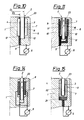
- FIG. 1 shows a pressure sensor according to the invention in an axial section
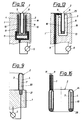
- FIG. 16 shows a pressure sensor according to the invention with a toroidal membrane
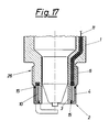
- FIG. 17 shows a pressure sensor integrated in a spark plug .
- the embodiment variants of a pressure sensor shown in FIGS. 1 to 17 have a membrane part 2 arranged on or in a holder 1, which is deformed by the pressure to be measured and which directly or indirectly generates a signal dependent on the pressure.
- the membrane part 2 has one or more pairs of concentrically arranged cylindrical regions 3 and 4, which have a small radial distance from one another in comparison to the cylinder diameter (shown exaggerated in the drawings).
- the diameter D 1 of the cylindrical region 3 is enlarged and the diameter D 2 of the region 4 is reduced by the pressure to be measured.
- the pressure sensor can be inserted, for example, into a measuring bore via a thread 6 provided on the holder 1.
- the membrane part 2 which delimits an essentially U-shaped annular space 7, is fastened on the outside to the holder 1 and is acted upon by the pressure to be measured from the outside or on the side facing away from the annular space 7.
- the membrane part 2 is arranged in an annular groove 8 in the holder 1.
- the membrane part 2 is open to the medium to be measured and is acted upon from the inside or the side facing the annular space by the pressure to be measured.
- the membrane part 2 can be both as a one-piece rotating body, such as in Fig. 1, 5, 12 or 16, and in several parts, such as 2, 6 or 10.
- the diaphragm part 2 is fastened to the holder 1 with its free edges 9 and has in its U-shaped annular space a cylindrical electrode 10 of a capacitive measuring system which is connected via a line 11 to the evaluation or Display device 5 is connected.
- the second electrode of the capacitive measuring system is formed by the cylindrical regions 3 and 4 of the membrane part 2 which are at zero potential and are closed in the circumferential direction. When the pressure rises, both cylindrical regions 3 and 4 are pressed closer to the electrode 10, the signal components of which add up.
- both diameters D 1 and D 2 enlarge in the same direction, so that in the first approximation - if the slightly different diameters D 1 and D 2 are neglected - no signal contribution from the temperature increase is to be expected.
- FIG. 5 An embodiment similar to that in FIG. 1 is shown in FIG. 5. Here several pairs of concentric areas 3 and 4 are combined to form a membrane part 2. The signal parts of the cylindrical electrodes 10 immersed in the individual annular spaces 7 become summed up to an output signal.
- the membrane part 2 can be connected to the holder 1 with its edge 9, but also with the curved regions 9 '.
- the membrane part 2 can, as shown in FIGS. 2 and 6, be made in several parts, wherein an edge 9 of the cylindrical regions 3 and 4 is fastened to the holder 1 and the edges 12 protruding from the holder (or into the Groove 8 of the bracket protruding edges) are connected in pairs to a support element 13. 2 and 6, the cylindrical regions 3 and 4 each form a cylindrical electrode or counter electrode of a capacitive measuring system.
- the support element 13 also serves as electrical insulation.
- FIG 3 shows a mechanically particularly stable embodiment variant, in which the cylindrical electrode 4 ′ present in the annular space 7 is coupled to one of the cylindrical regions 4 with the interposition of an insulating layer 14.
- the metallic membrane part 2 has on the inner surface of its cylindrical regions 3 and 4 each an insulating layer 16, 17 which carry the electrodes 3 ', 4' of a capacitive system. With this structure, external electric fields are shielded from the electrodes 3 ', 4'.
- the electrodes 3 ', 4' are connected to the evaluation or display device 5 via lines 11, 11 '.
- the insulating layers can also carry strain gauges 18 as a pressure measuring element.
- the membrane part 2 can also consist of an electrical insulator, the cylindrical regions 3 and 4 of which carry electrodes of a capacitive measuring system.
- the gaps a 1 and a 2 between the cylindrical regions 3 and 4 and the cylindrical electrode 10 can be of different widths such that signal contributions due to temperature deformation cancel each other out in certain regions.
- the two different areas 3 and 4 can e.g. B. welded together (see weld 15) or be connected pressure-tight according to FIG. 2 by an insulating support element 13 already mentioned.
- a pressure-sensitive element for example a piezoelectric element 19, is conceivable as a further pressure measuring element according to FIG. 8, which is in segments or as a piezoelectric film or foil between the cylindrical regions 3 and 4 of the membrane part 2 or between a respective cylindrical region 3 and 4 and an adjacent one cylindrical wall of the annular groove 8 (see Fig. 14) is arranged.
- other elements which change an electrical property when pressurized can also be used, for example semiconductors, the resistance of which varies with the mechanical load.
- FIG. 9 there is a pressure transmission medium 20 in the annular space 7 between the two cylindrical regions 3 and 4 of the membrane part 2, which pressure medium is connected to a pressure measuring element 21 arranged in the holder 1.
- FIG. 15 A similar embodiment variant with a membrane part 2 arranged in an annular groove 8 of the holder 1 is shown in FIG. 15.
- the pressure transmission medium 20 is located in an annular space 22 delimited by the annular groove 8 and the membrane part 2 arranged therein.
- the membrane part 2 is arranged in an annular groove 8 of the holder 1, which forms a sensor housing. Subsequent to a narrow edge area 23, where the membrane part 2 is held, the groove 8 has an extension or recess which serves to expose the cylindrical areas 3 and 4 and / or to accommodate a pressure measuring element.
- the cylindrical regions 3 and 4 can additionally be firmly anchored at the edges 12 in the lower region of the groove 8, which results in a robust, vibration-insensitive pressure sensor. While the two cylindrical regions 3 and 4 form the electrode plus counter electrode of a capacitive measuring system in FIG. 10, one of which is at zero potential and the other is electrically insulated from the holder 1, the membrane part 2 in FIG. 11 is entirely at zero -Potential and two electrodes 10 and 10 'on insulating layers 16 and 17 form the second electrode of the capacitive measuring system.
- the insulating layers can also be omitted if the housing or the holder 1 consists of an electrically insulating material.
- the design variants according to FIGS. 12 and 13 correspond in principle to those according to FIGS. 11 and 10, the cylindrical regions 3, 4 being connected to the holder 1 at only one edge 9 and the other edges freely in the groove 8 protruding.
- the membrane part 2 is designed as a one-piece rotating body in FIG. 12 and consists of two separate cylindrical parts in FIG. 13, which are connected by an insulating support element 13.
- strain gauges 18 instead of the capacitive measuring system, which are applied to the cylindrical regions 3 and 4 either directly or with the interposition of an insulating layer.
- FIG. 16 shows a pressure sensor with a closed, toroidal membrane part 2.
- the cylindrical regions 3 and 4 radially delimit a closed annular space 24 which receives the pressure measuring element, in the example shown an electrode 10 of a capacitive measuring system.
- the cylindrical electrode 10 is supported on the membrane part 2 via an electrically insulating support element 25. If the holder 1 is designed as an insulated cable, the cables 11, 11 ′ which are in contact with the membrane portion 2 and with the electrode 10 are received by this cable.
- the measuring principle on which the invention is based to a membrane part which has two concentric spherical surfaces, one spherical surface being pressurized from the outside and the other through at least one opening in the spherical surfaces from the inside. Between the two spherical surfaces is one of the pressure measuring elements mentioned in the preceding examples.
- the described variants of the pressure sensor can - as shown in Fig. 17 - also, for example, in a pressure chamber, for. B. an internal combustion engine protruding front part 26 of a spark plug (also glow plug, injection nozzle or the like.), An embodiment variant of the membrane part, comparable to FIG. 1 or FIG. 7, being chosen here.
Landscapes
- Physics & Mathematics (AREA)
- General Physics & Mathematics (AREA)
- Chemical & Material Sciences (AREA)
- Engineering & Computer Science (AREA)
- Combustion & Propulsion (AREA)
- Measuring Fluid Pressure (AREA)
Applications Claiming Priority (2)
| Application Number | Priority Date | Filing Date | Title |
|---|---|---|---|
| AT2492/91 | 1991-12-16 | ||
| AT0249291A AT399588B (de) | 1991-12-16 | 1991-12-16 | Drucksensor |
Publications (3)
| Publication Number | Publication Date |
|---|---|
| EP0548043A2 true EP0548043A2 (fr) | 1993-06-23 |
| EP0548043A3 EP0548043A3 (fr) | 1993-08-11 |
| EP0548043B1 EP0548043B1 (fr) | 1996-02-14 |
Family
ID=3535271
Family Applications (1)
| Application Number | Title | Priority Date | Filing Date |
|---|---|---|---|
| EP92890260A Expired - Lifetime EP0548043B1 (fr) | 1991-12-16 | 1992-12-14 | Capteur de pression |
Country Status (6)
| Country | Link |
|---|---|
| US (1) | US5353643A (fr) |
| EP (1) | EP0548043B1 (fr) |
| JP (1) | JPH0769241B2 (fr) |
| KR (1) | KR960005643B1 (fr) |
| AT (2) | AT399588B (fr) |
| DE (1) | DE59205355D1 (fr) |
Cited By (2)
| Publication number | Priority date | Publication date | Assignee | Title |
|---|---|---|---|---|
| EP1847777A2 (fr) | 2006-04-20 | 2007-10-24 | Piezocryst Advanced Sensorics GmbH | Bougie de préchauffage dotée d'un capteur de pression intégré |
| CN114323363A (zh) * | 2022-03-15 | 2022-04-12 | 季华实验室 | 一种电容式真空压力传感器 |
Families Citing this family (11)
| Publication number | Priority date | Publication date | Assignee | Title |
|---|---|---|---|---|
| FR2679652B1 (fr) * | 1991-07-26 | 1993-11-12 | Schlumberger Services Petroliers | Procede pour corriger de l'influence de la temperature les mesures d'une jauge de pression. |
| US5808205A (en) * | 1997-04-01 | 1998-09-15 | Rosemount Inc. | Eccentric capacitive pressure sensor |
| US20020111662A1 (en) * | 2001-02-09 | 2002-08-15 | Iaizzo Paul A. | System and method for placing an implantable medical device within a body |
| EP1381811A1 (fr) * | 2001-04-27 | 2004-01-21 | Siemens Aktiengesellschaft | Chambre de combustion, en particulier d'une turbine a gaz |
| DE10312491B3 (de) * | 2003-03-20 | 2005-02-03 | Robert Bosch Gmbh | Drucksensor mit Hitzeschild zum Einsatz in Verbrennungskraftmaschinen |
| DE10343521A1 (de) * | 2003-09-19 | 2005-04-21 | Beru Ag | Druckmessglühkerze für einen Dieselmotor |
| EP2087333B1 (fr) * | 2006-11-10 | 2011-08-17 | Kistler Holding AG | Capteur de pression pour effectuer des mesures dans le cadre de processus dynamiques à haute température |
| WO2012115036A1 (fr) * | 2011-02-25 | 2012-08-30 | 本田技研工業株式会社 | Dispositif de détection de la pression intérieure d'un cylindre d'un moteur à combustion interne du type à injection directe |
| US8899105B2 (en) * | 2012-08-29 | 2014-12-02 | Goutham R. Kirikera | Slim capacitance sensor for downhole applications |
| EP3399294A1 (fr) * | 2017-05-02 | 2018-11-07 | HIDRIA AET Druzba za proizvodnjo vzignih sistemov in elektronike d.o.o. | Capteur de pression |
| US10996120B1 (en) * | 2019-11-06 | 2021-05-04 | Vibration Measurement Solutions, Inc. | Pressure sensor |
Family Cites Families (9)
| Publication number | Priority date | Publication date | Assignee | Title |
|---|---|---|---|---|
| US3645137A (en) * | 1970-04-16 | 1972-02-29 | Bendix Corp | Quartz pressure sensor |
| CH587478A5 (fr) * | 1974-11-08 | 1977-04-29 | Kistler Instrumente Ag | |
| US4064549A (en) * | 1976-08-31 | 1977-12-20 | Metrolology General Corporation | Cylindrical capacitive quartz transducer |
| AT374922B (de) * | 1979-08-09 | 1984-06-12 | List Hans | Messanordner mit einem druckgeber zum messen des druckes heisser medien |
| DE3021088A1 (de) * | 1980-06-04 | 1981-12-10 | Robert Bosch Gmbh, 7000 Stuttgart | Sensor |
| EP0160713A1 (fr) * | 1984-05-04 | 1985-11-13 | Kristal Instrumente AG | Capteur de pression, en particulier pour la surveillance de systèmes d'injection de fluide combustible |
| US4646406A (en) * | 1984-11-15 | 1987-03-03 | Weiss Instruments Inc. | Welded edge bourdon strip thermometer-manometer |
| US4772983A (en) * | 1987-04-20 | 1988-09-20 | Linear Measurements, Inc. | Method and article for a nearly zero temperature coefficient pressure transducer |
| US4777827A (en) * | 1988-01-14 | 1988-10-18 | Sealed Unit Parts Co., Inc. | Digital pressure gauge |
-
1991
- 1991-12-16 AT AT0249291A patent/AT399588B/de not_active IP Right Cessation
-
1992
- 1992-12-14 AT AT92890260T patent/ATE134268T1/de not_active IP Right Cessation
- 1992-12-14 EP EP92890260A patent/EP0548043B1/fr not_active Expired - Lifetime
- 1992-12-14 JP JP4333265A patent/JPH0769241B2/ja not_active Expired - Lifetime
- 1992-12-14 DE DE59205355T patent/DE59205355D1/de not_active Expired - Fee Related
- 1992-12-15 US US07/990,799 patent/US5353643A/en not_active Expired - Fee Related
- 1992-12-16 KR KR1019920024416A patent/KR960005643B1/ko not_active Expired - Fee Related
Cited By (3)
| Publication number | Priority date | Publication date | Assignee | Title |
|---|---|---|---|---|
| EP1847777A2 (fr) | 2006-04-20 | 2007-10-24 | Piezocryst Advanced Sensorics GmbH | Bougie de préchauffage dotée d'un capteur de pression intégré |
| EP1847777A3 (fr) * | 2006-04-20 | 2008-05-28 | Piezocryst Advanced Sensorics GmbH | Bougie de préchauffage dotée d'un capteur de pression intégré |
| CN114323363A (zh) * | 2022-03-15 | 2022-04-12 | 季华实验室 | 一种电容式真空压力传感器 |
Also Published As
| Publication number | Publication date |
|---|---|
| US5353643A (en) | 1994-10-11 |
| EP0548043A3 (fr) | 1993-08-11 |
| DE59205355D1 (de) | 1996-03-28 |
| ATA249291A (de) | 1994-10-15 |
| KR930013702A (ko) | 1993-07-22 |
| ATE134268T1 (de) | 1996-02-15 |
| JPH0769241B2 (ja) | 1995-07-26 |
| JPH05248977A (ja) | 1993-09-28 |
| KR960005643B1 (ko) | 1996-04-30 |
| EP0548043B1 (fr) | 1996-02-14 |
| AT399588B (de) | 1995-06-26 |
Similar Documents
| Publication | Publication Date | Title |
|---|---|---|
| DE4111869C2 (fr) | ||
| DE3883067T2 (de) | Kapazitives Manometer zur Absolutdruckmessung. | |
| EP0548043B1 (fr) | Capteur de pression | |
| DE3838333C2 (fr) | ||
| DE60031869T2 (de) | Kapazitiver druckwandler | |
| EP1856497B1 (fr) | Composant pour capteurs de force ou de pression, dont les elements sont maintenus les uns avec les autres par un film electro-isolant | |
| DE3310643C2 (de) | Drucksensor | |
| DE2514511C2 (de) | Kapazitiver Meßfühler | |
| DE2820478A1 (de) | Kapazitiver druckfuehlerwandler und verfahren zu seiner herstellung | |
| EP0718612B1 (fr) | Bougie avec élément de mesure de force et isolateur divisé | |
| EP0065511A1 (fr) | Instrument de mesure avec un élément de détection piézoélectrique | |
| DE4031791A1 (de) | Sensor fuer ein kapazitaetsmanometer | |
| DE3827138C2 (fr) | ||
| EP1336086A1 (fr) | Cellule de mesure de pression | |
| EP2013597B1 (fr) | Élément de mesure piézoélectrique à effet transversal, et capteur équipé de cet élément de mesure | |
| DE4011734A1 (de) | Kapazitiver differenzdruckdetektor | |
| DE29619778U1 (de) | Druck- und Temperatursensor | |
| EP2223066A2 (fr) | Composant pour mesurer une force ou une pression et capteur comprenant un tel composant | |
| EP0373536A2 (fr) | Capteur de pression capacitif résistant aux surcharges | |
| EP2317294B1 (fr) | Cellule de mesure | |
| WO2001023855A2 (fr) | Systeme de capteur de pression | |
| EP1608941B1 (fr) | Capteur de pression a dispositif antiretour de flamme | |
| DE4418656A1 (de) | Gekühlter Drucksensor | |
| EP3001167B1 (fr) | Systeme de capteur et procede de fabrication d'un systeme de capteur | |
| DE4224524A1 (de) | Elektrostatischer kapazitaetstyp-differenzdruckdetektor |
Legal Events
| Date | Code | Title | Description |
|---|---|---|---|
| PUAI | Public reference made under article 153(3) epc to a published international application that has entered the european phase |
Free format text: ORIGINAL CODE: 0009012 |
|
| AK | Designated contracting states |
Kind code of ref document: A2 Designated state(s): AT BE CH DE DK ES FR GB IT LI LU NL SE |
|
| PUAL | Search report despatched |
Free format text: ORIGINAL CODE: 0009013 |
|
| AK | Designated contracting states |
Kind code of ref document: A3 Designated state(s): AT BE CH DE DK ES FR GB IT LI LU NL SE |
|
| 17P | Request for examination filed |
Effective date: 19930824 |
|
| 17Q | First examination report despatched |
Effective date: 19941215 |
|
| GRAA | (expected) grant |
Free format text: ORIGINAL CODE: 0009210 |
|
| AK | Designated contracting states |
Kind code of ref document: B1 Designated state(s): AT BE CH DE DK ES FR GB IT LI LU NL SE |
|
| PG25 | Lapsed in a contracting state [announced via postgrant information from national office to epo] |
Ref country code: NL Free format text: LAPSE BECAUSE OF FAILURE TO SUBMIT A TRANSLATION OF THE DESCRIPTION OR TO PAY THE FEE WITHIN THE PRESCRIBED TIME-LIMIT Effective date: 19960214 Ref country code: GB Effective date: 19960214 Ref country code: ES Free format text: THE PATENT HAS BEEN ANNULLED BY A DECISION OF A NATIONAL AUTHORITY Effective date: 19960214 Ref country code: DK Effective date: 19960214 Ref country code: BE Effective date: 19960214 |
|
| REF | Corresponds to: |
Ref document number: 134268 Country of ref document: AT Date of ref document: 19960215 Kind code of ref document: T |
|
| REF | Corresponds to: |
Ref document number: 59205355 Country of ref document: DE Date of ref document: 19960328 |
|
| ET | Fr: translation filed | ||
| ITF | It: translation for a ep patent filed | ||
| PG25 | Lapsed in a contracting state [announced via postgrant information from national office to epo] |
Ref country code: SE Effective date: 19960514 |
|
| NLV1 | Nl: lapsed or annulled due to failure to fulfill the requirements of art. 29p and 29m of the patents act | ||
| GBV | Gb: ep patent (uk) treated as always having been void in accordance with gb section 77(7)/1977 [no translation filed] |
Effective date: 19960214 |
|
| PG25 | Lapsed in a contracting state [announced via postgrant information from national office to epo] |
Ref country code: AT Effective date: 19961214 |
|
| PLBE | No opposition filed within time limit |
Free format text: ORIGINAL CODE: 0009261 |
|
| PG25 | Lapsed in a contracting state [announced via postgrant information from national office to epo] |
Ref country code: LU Free format text: LAPSE BECAUSE OF NON-PAYMENT OF DUE FEES Effective date: 19961231 Ref country code: LI Effective date: 19961231 Ref country code: CH Effective date: 19961231 |
|
| 26N | No opposition filed | ||
| REG | Reference to a national code |
Ref country code: CH Ref legal event code: PL |
|
| PGFP | Annual fee paid to national office [announced via postgrant information from national office to epo] |
Ref country code: FR Payment date: 19991230 Year of fee payment: 8 |
|
| PG25 | Lapsed in a contracting state [announced via postgrant information from national office to epo] |
Ref country code: FR Free format text: LAPSE BECAUSE OF NON-PAYMENT OF DUE FEES Effective date: 20010831 |
|
| REG | Reference to a national code |
Ref country code: FR Ref legal event code: ST |
|
| PG25 | Lapsed in a contracting state [announced via postgrant information from national office to epo] |
Ref country code: IT Free format text: LAPSE BECAUSE OF NON-PAYMENT OF DUE FEES;WARNING: LAPSES OF ITALIAN PATENTS WITH EFFECTIVE DATE BEFORE 2007 MAY HAVE OCCURRED AT ANY TIME BEFORE 2007. THE CORRECT EFFECTIVE DATE MAY BE DIFFERENT FROM THE ONE RECORDED. Effective date: 20051214 |
|
| PGFP | Annual fee paid to national office [announced via postgrant information from national office to epo] |
Ref country code: DE Payment date: 20051223 Year of fee payment: 14 |
|
| PG25 | Lapsed in a contracting state [announced via postgrant information from national office to epo] |
Ref country code: DE Free format text: LAPSE BECAUSE OF NON-PAYMENT OF DUE FEES Effective date: 20070703 |