EP0548059B1 - Moteurs sans balai - Google Patents
Moteurs sans balai Download PDFInfo
- Publication number
- EP0548059B1 EP0548059B1 EP93200535A EP93200535A EP0548059B1 EP 0548059 B1 EP0548059 B1 EP 0548059B1 EP 93200535 A EP93200535 A EP 93200535A EP 93200535 A EP93200535 A EP 93200535A EP 0548059 B1 EP0548059 B1 EP 0548059B1
- Authority
- EP
- European Patent Office
- Prior art keywords
- circuit
- masking
- reference position
- delay
- signal
- Prior art date
- Legal status (The legal status is an assumption and is not a legal conclusion. Google has not performed a legal analysis and makes no representation as to the accuracy of the status listed.)
- Expired - Lifetime
Links
Images


Classifications
-
- H—ELECTRICITY
- H02—GENERATION; CONVERSION OR DISTRIBUTION OF ELECTRIC POWER
- H02P—CONTROL OR REGULATION OF ELECTRIC MOTORS, ELECTRIC GENERATORS OR DYNAMO-ELECTRIC CONVERTERS; CONTROLLING TRANSFORMERS, REACTORS OR CHOKE COILS
- H02P6/00—Arrangements for controlling synchronous motors or other dynamo-electric motors using electronic commutation dependent on the rotor position; Electronic commutators therefor
- H02P6/04—Arrangements for controlling or regulating the speed or torque of more than one motor
-
- H—ELECTRICITY
- H02—GENERATION; CONVERSION OR DISTRIBUTION OF ELECTRIC POWER
- H02P—CONTROL OR REGULATION OF ELECTRIC MOTORS, ELECTRIC GENERATORS OR DYNAMO-ELECTRIC CONVERTERS; CONTROLLING TRANSFORMERS, REACTORS OR CHOKE COILS
- H02P6/00—Arrangements for controlling synchronous motors or other dynamo-electric motors using electronic commutation dependent on the rotor position; Electronic commutators therefor
- H02P6/14—Electronic commutators
- H02P6/16—Circuit arrangements for detecting position
- H02P6/18—Circuit arrangements for detecting position without separate position detecting elements
- H02P6/182—Circuit arrangements for detecting position without separate position detecting elements using back-emf in windings
-
- H—ELECTRICITY
- H02—GENERATION; CONVERSION OR DISTRIBUTION OF ELECTRIC POWER
- H02P—CONTROL OR REGULATION OF ELECTRIC MOTORS, ELECTRIC GENERATORS OR DYNAMO-ELECTRIC CONVERTERS; CONTROLLING TRANSFORMERS, REACTORS OR CHOKE COILS
- H02P6/00—Arrangements for controlling synchronous motors or other dynamo-electric motors using electronic commutation dependent on the rotor position; Electronic commutators therefor
- H02P6/08—Arrangements for controlling the speed or torque of a single motor
- H02P6/085—Arrangements for controlling the speed or torque of a single motor in a bridge configuration
-
- H—ELECTRICITY
- H02—GENERATION; CONVERSION OR DISTRIBUTION OF ELECTRIC POWER
- H02P—CONTROL OR REGULATION OF ELECTRIC MOTORS, ELECTRIC GENERATORS OR DYNAMO-ELECTRIC CONVERTERS; CONTROLLING TRANSFORMERS, REACTORS OR CHOKE COILS
- H02P6/00—Arrangements for controlling synchronous motors or other dynamo-electric motors using electronic commutation dependent on the rotor position; Electronic commutators therefor
- H02P6/12—Monitoring commutation; Providing indication of commutation failure
-
- H—ELECTRICITY
- H02—GENERATION; CONVERSION OR DISTRIBUTION OF ELECTRIC POWER
- H02P—CONTROL OR REGULATION OF ELECTRIC MOTORS, ELECTRIC GENERATORS OR DYNAMO-ELECTRIC CONVERTERS; CONTROLLING TRANSFORMERS, REACTORS OR CHOKE COILS
- H02P6/00—Arrangements for controlling synchronous motors or other dynamo-electric motors using electronic commutation dependent on the rotor position; Electronic commutators therefor
- H02P6/14—Electronic commutators
- H02P6/15—Controlling commutation time
-
- H—ELECTRICITY
- H02—GENERATION; CONVERSION OR DISTRIBUTION OF ELECTRIC POWER
- H02P—CONTROL OR REGULATION OF ELECTRIC MOTORS, ELECTRIC GENERATORS OR DYNAMO-ELECTRIC CONVERTERS; CONTROLLING TRANSFORMERS, REACTORS OR CHOKE COILS
- H02P6/00—Arrangements for controlling synchronous motors or other dynamo-electric motors using electronic commutation dependent on the rotor position; Electronic commutators therefor
- H02P6/20—Arrangements for starting
- H02P6/21—Open loop start
Definitions
- This invention relates to brushless motors and, in particular, to brushless motors in which rotor position sensors are not required.
- a known brushless motor typically detects the angular position of the rotor by using a position sensor, such as a Hall-effect element. Upon determining the rotational position of the rotor, a switching pulse is produced that switches the phases of the stator coil energisation based upon the detected signal.
- a position sensor such as a Hall-effect element.
- a fixed time delay device such as a monostable multivibrator.
- This proposed system has the drawback that it is not applicable to motors in which the speed is controlled over a relatively wide range.
- the brushless motor utilised in a constant linear velocity (CLV) type of video disc player cannot easily be implemented with the previously proposed system.
- special energisation pulses are generated at fixed intervals and with fixed durations regardless of the initial angular position of the rotor. Therefore, the energisation angle of the stator coils is not synchronised with the rotational angle of the rotor resulting in poor starting characteristics.
- German Patent Application No. DE-A-2 604 638 discloses a brushless motor similar to that described above.
- EP-A-0 231 046 discloses a commutation circuit for a brushless motor in which a delay circuit provides a delay time during which the influence of transient effects causing parasitic zero crossings may be eliminated.
- a sensorless brushless motor comprising:
- Figure 1 shows a drive circuit for a sensorless brushless motor, which in this embodiment is assumed to be of the two-phase bidirectional energisation type.
- a motor includes a rotor 21 as shown in Figure 3A, which comprises magnets arranged to form eight poles.
- Figure 3B is a plan view of a stator for such a motor having two-phase coils La1, La2 and Lb1, Lb2 having an electrical angle of 90° and a mechanical angle of 67.5° formed on a stator base 22.
- the stator coils consist of two pairs of series coils La1 and La2, and Lb1 and Lb2, respectively, which are arranged at electrically in-phase positions, that is, arranged at an integer multiple of an electrical angle of 360°.
- the winding pitch of each coil is an electrical angle of 180° or a mechanical angle of 45°.
- the two-phase coils La and Lb are reciprocally connected to an energisation circuit by a switching circuit 1, as shown in Figure 1.
- Such reciprocal connection or switching is also known as bidirectional switching.
- FIG. 2 shows the switching circuit 1 of Figure 1 in more detail, in which transistors 11, 12, 13 and 14 are bridge-connected to the coil La, and transistors 15, 16, 17 and 18 are bridge-connected to the coil Lb.
- the transistors 11 to 18 are then turned on every electrical angle of 90° by drive pulses P1 to P8 which are applied to the base circuits of the transistors 11 to 18, respectively. Accordingly, the ends of each load or coil, La and Lb, are selectively connected between the positive terminal (+) of a power supply and its earth or ground terminal, thereby providing a driving force for the motor.
- pulse signals S1 and S2 ( Figure 4B) having a mutual phase difference of 90° corresponding to the induced voltages Ea and Eb are obtained as the outputs from the comparators 19 and 20.
- These pulse signals S1 and S2 are therefore synchronised and phase-locked with the induced voltages Ea and Eb, and their high and low levels correspond to the respective AC polarities of the induced voltages, as shown in Figure 4B.
- the pulse signals S1 and S2 indicate a reference angular position of the rotor relative to the stator coils La and Lb.
- the pulse signals S1 and S2 are then fed to a delay circuit 5 that forms a delay clock signal DCK, the leading edges of which are delayed by a time T from the leading and trailing edges of the pulse signals S1 and S2, as shown in Figure 4C.
- the manner in which the clock signal DCK is produced will be explained in detail below.
- the trailing edges of the clock signal DCK are synchronised with the pulse signals S1 and S2 and the time T corresponds to an electrical angle of 45°. Therefore, an energisation angle having a 90° width with a leading edge corresponding to a 45° position from the magnetic pole boundary corresponding to the reference position of the rotor magnet 21 can be obtained without an angular position sensor, which would otherwise be required.
- the time T can be variably controlled by a microprocessor 7 so that it is always kept at an electrical angle of 45°, even if the rotational speed of the motor is varied.
- the pulse signals S1 and S2 from the switching circuit 1 in Figure 1 are also fed to a masking circuit 8, which can optionally share common elements with the delay circuit 5.
- the masking circuit 8 transforms the pulse signals S1 and S2 into signals S11 and S12, respectively, which are then fed to the D inputs of respective D-type flip-flops 3 and 4.
- the operation of the masking circuit 8 will be explained hereinbelow, and at this time it is to be noted that the masking circuit 8 removes the noise pulses included in the pulse signals S1 and S2 at all portions other than the zero crossing sections of the induced voltage signals Ea and Eb.
- the noise pulses are based upon the energisation switching of the stator coils, the noise pulses are generated at specific positions and, thus, the masking position and according to the invention the widths of the masking pulses are controlled by the control data according to the motor speed from the microprocessor 7.
- the flip-flops 3 and 4 receive the delayed clock signal DCK at the respective clock inputs thereof and, thus, the flip-flops 3 and 4 produce pulse signals Ha and Hb, delayed by 45° relative to the pulse signals S1 and S2, as shown in Figure 4D.
- These pulse signals Ha and Hb are fed to a drive pulse generator logic circuit 2 that forms the bidirectional energisation pulses P1 to P8 at every 90° electrical angle, as shown in Figure 4E.
- the drive pulse generator logic circuit 2 produces the bidirectional energisation pulses P1 to P8 by straightforward logic processing or encoding so that the polarities of the magnetic poles of the rotor correspond to the energisation polarities during the 90° wide intervals (45°-135° and 225°-315°) of the magnetic poles opposite the coils La and Lb. In this fashion, rotational torque in one direction is generated.
- a start pulse signal is generated by a start pulse generator 6 for a period of time.
- the start pulse generator 6 is controlled by the microprocessor 7 to which the motor start switch (not shown) is connected.
- the start pulse generator 6 supplies start pulse signals to the set (S) and reset (R) terminals of the flip-flops 3 and 4, thereby forming two-phase pulse signals similar to the pulse signals Ha and Hb shown in Figure 4D.
- the coils La and Lb are separately excited by the start pulse signals from the start pulse generator 6, and the rotor 21 is caused to rotate in a predetermined rotational direction depending upon the phase relationship between the start pulse signals produced by the start pulse generator 6 as determined by the microprocessor 7.
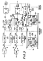
- the delay circuit 5 of Figure 1 is shown in more detail in Figure 5, as is the masking circuit 8.
- Figure 6 represents waveforms appearing throughout the circuit of Figure 5 during operation thereof. More specifically, the induced voltages Ea and Bb induced respectively in the coils La and Lb are applied to the comparators 19 and 20, respectively, and are so-called zero-cross shaped therein.
- the comparators 19 and 20 form the pulse signals S1 and S2 also shown in Figure 6, and in accordance with typical comparator operation, the comparators 19 and 20 in addition to detecting the induced voltages Ea and Eb will also detect the noise spikes caused by the stator coil switching.
- noise spikes are shown at N in the voltage waveforms Ea and Eb in Figure 6, and because they are generated at the current switching positions, noise will be found at the corresponding points 45°, 135°, 225° and 315°, of the induced voltage signals Ea and Eb.
- the noise spikes N will be detected by the comparators 19 and 20 and will result in noise pulses Pn being present in the pulse signals S1 and S2. It is these noise pulses Pn that are removed by the masking circuit 8.
- the output (S1) from the comparator 19 is fed to a leading edge detector B11 and a trailing edge detector B12, and the output (S2) of the comparator 20 is fed to a leading edge detector B21 and a trailing edge detector B22.
- the pulse signal S1 is developed into edge pulses S3 and S4 as shown in Figure 6, and the pulse signal S2 is developed into edge pulses S5 and S6, also as shown in Figure 6.
- These edge pulses S3, S4, S5 and S6 are fed to respective masking AND gates G11, G12, G21 and G22.
- these masking AND gates G11, G12, G21 and G22 serve to remove the noise pulses Pn, with the resultant signals being shown in Figure 6 as edge pulses S7, S8, S9 and S10, respectively.
- the edge pulses S7 and S8 are fed to an RS flip-flop formed by NOR gates G13 and G14, and the edge pulses S9 and S10 are fed to a second RS flip-flop formed by NOR gates G23 and G24.
- These two sets of NOR gates then produce the pulse signals S11 and S12, as shown in Figure 6.
- the pulse signals S11 and S12 have the noise pulses Pn removed therefrom at points other than the zero-crossing points of the pulse signals S1 and S2.
- the pulse signals S11 and S12 are fed to the clock inputs of the D-type flip-flops 3 and 4, which act to form delayed pulses S13 and S14 that correspond to the signals Ha and Hb in Figure 6, respectively.
- the outputs (S7, S8, S9 and S10) from the masking AND gates G11, G12, G21 and G22 are also connected to a multiple input OR gate G31, so that a pulse signal indicating two edges of the two-phase signal is formed, that is, the pulses indicate the leading and trailing edges of each of the two signals, as shown by the signal S16 in Figure 6.
- the signal S16 is supplied as a load pulse to a terminal LD of a delay counter 26, which forms the delay circuit 5 shown in Figure 1.
- the load input of the counter 26 then causes control data D0 to Dn corresponding to the rotational speed of the motor to be input to the counter 26 from a data bus 28 of the microprocessor 7 through a latch circuit 27.
- the counter 26 counts the delay clock signals having a predetermined frequency fed in from an external clock circuit (not shown) through an OR gate G33 in response to the load pulse S16 based on the load data. Accordingly, the delay counter 26 will generate an nth-bit (most significant bit) output with the leading edge occurring after a time T, as shown in a waveform S17 of Figure 6.
- the frequency of the delay clock signal is based on the resolution (resolving power or resolving efficiency) of the counter 26.
- the locations of the load pulses in the waveform S16 correspond to electrical angles of 0°, 90°, 180° and 270°, and the time T is controlled, that is, lengthened or shortened, in accordance with the load data, as fed in from the microprocessor 7.
- the time T is controlled to correspond to each 45° width between the electrical angles 0° and 45°, between 90° and 135°, between 180° and 225°, and between 270° and 315°, regardless of change in rotational speed of the motor. In other words, at low speed the time T is lengthened and at high speed the time T is shortened.
- the delay counter 26 then counts the clock signals fed in through the OR gate G33 and, upon reaching the most significant bit Qn, the output of the counter 26 goes high. This output of the counter 26 is connected to another input of the OR gate G33, thereby blocking the clock input to the counter 26. Therefore, the most significant bit output Qn of the counter 26, shown by the waveform S17 in Figure 6, remains at a high level until the next load pulse S16 is fed to the counter 26 to reset the counter and, thus, the most significant bit level output Qn falls to a low level.
- the counter output S17 is also fed to the clock inputs of the flip-flops 3 and 4 as the delayed clock signal DCK in the circuit of Figure 1, which signal waveforms are also shown in Figure 4C, thereby forming the delayed pulse signals Ha and Hb, which correspond respectively to the signals S13 and S14 in Figure 6.
- the most significant bit output from the delay counter 26 is also fed to a third leading edge detector 25, so that a pulse representing the leading edge indicated by an edge pulse signal waveform S18 in Figure 6 is formed.
- the edge pulse signal S18 represents the positions at electrical angles of 45°, 135°, 225° and 315° of respective phases of the two-phase signal.
- This signal is also fed to an OR gate G32 that forms an OR output signal S19 from the edge pulse signal S18 and the output pulse signal S16, which corresponds to 0° and 180° electrical angle, of the multiple input OR gate G31.
- the interval between pulses of the output pulse signal S19 is lengthened or shortened in accordance with the delay time T; however, the electrical phase angle remains constant at 0°, 45°, 135°, 180°, 225° and 315°.
- This OR gate output pulse signal S19 is fed as the load pulse to an input LD of a masking counter 29, which comprises the masking circuit 8 of Figure 1.
- the masking counter 29 fetches control data corresponding to the rotational speed of the motor from the data bus 28 of the microprocessor 7 through a latch circuit 30, in an operation similar to that of the delay counter 26.
- the masking counter 29 counts masking clock pulses provided by an external clock circuit (not shown) at a predetermined frequency by receiving a clock signal through an OR gate G34 at a clock input CK.
- the frequency of the masking clock is determined by the resolution or resolving power, or the resolving efficiency, of the masking counter 29.
- the masking counter 29 generates from the most significant bit (MSB) position Qn a masking pulse signal that falls at angular positions of 0°, 180°, 45°, 135° and 315°, as indicated by the pulse signal S15 in Figure 6, in which the masking pulse rises after lapse of a predetermined time period t, termed the masking width. Because the masking clock input to the masking counter 29 is connected through the OR gate G34 that has as another input signal the MSB signal S15 from the masking counter 29 when the MSB signal goes to a high level, the masking clock is disabled by the OR gate G34 and the counting operation is interrupted until the next load pulse provided by the output signal S19 is fed to the masking counter 29.
- MSB most significant bit
- the masking width t is varied in accordance with the rotational speed of the motor as determined by the microprocessor 7.
- the masking pulse S15 is also fed to the masking AND gates G11, G12, G21 and G22 so that the AND gates are closed during the low-level period t of the masking pulse signal S15.
- This has the effect that predetermined periods immediately following the zero-crossing detection at 0° and 180°, and at predetermined periods immediately after the current switching timings at 45°, 135°, 225° and 315°, are masked, as indicated by the induced voltage waveforms Ea and Eb in Figure 6.
- the zero-crossing detection pulse signals S11 and S12 are also fed to the microprocessor 7.
- the periods of the pulse signals S11 and S12 are detected therein so that the rotational speed of the motor can be determined.
- Control data formed by speed detection is then output on to the data bus 28, shown in Figure 5, in order to determine the delay time T and the masking width t corresponding to each 45° interval between 0° and 45°, between 90° and 135°, between 180° and 225°, and between 270° and 315°.
- speed detection may be performed by a frequency generator or a pulse generator attached to the motor.
- the present invention is applied to a two-phase bidirectional energisation type sensorless brushless motor.
- the present invention finds equal application to a polyphase unidirectional motor or a bidirectional energisation type sensorless brushless motor.
Landscapes
- Engineering & Computer Science (AREA)
- Power Engineering (AREA)
- Control Of Motors That Do Not Use Commutators (AREA)
- Moving Of Head For Track Selection And Changing (AREA)
- Rotational Drive Of Disk (AREA)
- Control Of Stepping Motors (AREA)
Claims (9)
- Moteur à courant continu sans collecteur et sans capteur, comprenant:- un rotor (21);- un bobinage d'excitation (La, Lb);- un circuit de commutation (1) pour effectuer la commutation d'excitation du bobinage d'excitation (La, Lb);- un détecteur de position de référence (1ç, 20) pour détecter une position de référence de rotation du rotor sur la base d'une tension (S1, S2) induite dans ledit bobinage d'excitation (La, Lb) par ledit rotor;- un circuit à retard (5) pour produire un signal d'horloge à retard (DCK) ayant des impulsions retardées d'une valeur prédéterminée (T) par rapport à la position de référence détectée par ledit détecteur de position de référence (19, 20);- un circuit (3, 4) formant un signal à impulsions à retard pour produire un signal à impulsions à retard (Ha, Hb) sur la base du signal d'horloge à retard (DCK) issu dudit circuit à retard (5); et- un générateur de signal de commutation (2) pour produire un signal de commutation d'excitation (P1 à P8) appliqué audit circuit de commutation (1) en réponse au signal à impulsions à retard (Ha, Hb),caractérisé en ce que:- un circuit de masquage (8) est prévu pour former un signal de masquage du bruit (S15) ayant une largeur de masquage prédéterminée (t) basée sur au moins le signal d'horloge à retard (DCK) pour éliminer les impulsions de bruit (N) dans le signal de sortie de détection dudit détecteur de position de référence (19, 20) à la position de référence; et- un circuit de commande (7) est prévu pour faire varier la largeur de masquage (t) selon la vitesse de rotation dudit moteur.
- Moteur selon la revendication 1, dans lequel ledit circuit de masquage (8) fonctionne pour former le signal de masquage de bruit (S15) ayant la largeur de masquage prédéterminée (t) sur la base du signal d'horloge à retard (DCK) et du signal de sortie de détection du détecteur de position de référence (19, 20) immédiatement après la détection de la position de référence et la génération du signal de commutation.
- Moteur selon la revendication 1 ou la revendication 2, comprenant un circuit à porte de masquage (G11 à G22) pour recevoir une position de référence détectée issue dudit détecteur de position de référence (19, 20) et ledit signal de masquage du bruit (S15) et produire un signal à impulsions (S11, S12) dans lequel les impulsions de bruit (N) sont éliminées et qui est appliqué audit circuit formant le signal à impulsions à retard (3, 4).
- Moteur selon la revendication 3, comprenant des détecteurs de flancs avant et de flancs arrière (B11, B21, B12, B22) pour produire des impulsons de flancs (S3 à S6) pour fourniture audit circuit à porte de masquage (G11 à G22) sur la base de la position de référence détectée issue dudit détecteur de position de référence (19, 20).
- Moteur selon l'une quelconque des revendications précédentes, dans lequel ledit circuit de commutation (1) comprend une pluralité de transistors (11 à 18) connectés dans un réseau en pont à ladite bobine d'excitation (La, Lb).
- Moteur selon l'une quelconque des revendications précédentes, dans lequel ledit détecteur de position de référence comprend un comparateur de passage par zéro (19, 20).
- Moteur selon l'une quelconque des revendications précédentes, dans lequel ledit circuit à retard (5) comprend un compteur à retard (26), ledit signal d'horloge à retard (DCK) étant produit à une sortie de celui-ci.
- Moteur selon l'une quelconque des revendications précédentes, dans lequel ledit circuit formant un signal à impulsions à retard comprend une bascule (3, 4).
- Moteur selon l'une quelconque des revendications précédentes, dans lequel ledit circuit de masquage (8) comprend un compteur de masquage (29).
Applications Claiming Priority (3)
| Application Number | Priority Date | Filing Date | Title |
|---|---|---|---|
| JP276833/87 | 1987-10-31 | ||
| JP62276833A JP2875529B2 (ja) | 1987-10-31 | 1987-10-31 | センサレスブラシレスモータの駆動装置 |
| EP88309732A EP0316077B1 (fr) | 1987-10-31 | 1988-10-17 | Moteur sans balais |
Related Parent Applications (2)
| Application Number | Title | Priority Date | Filing Date |
|---|---|---|---|
| EP88309732.1 Division | 1988-10-17 | ||
| EP88309732A Division EP0316077B1 (fr) | 1987-10-31 | 1988-10-17 | Moteur sans balais |
Publications (3)
| Publication Number | Publication Date |
|---|---|
| EP0548059A2 EP0548059A2 (fr) | 1993-06-23 |
| EP0548059A3 EP0548059A3 (fr) | 1993-07-28 |
| EP0548059B1 true EP0548059B1 (fr) | 1997-01-29 |
Family
ID=17575038
Family Applications (2)
| Application Number | Title | Priority Date | Filing Date |
|---|---|---|---|
| EP88309732A Expired - Lifetime EP0316077B1 (fr) | 1987-10-31 | 1988-10-17 | Moteur sans balais |
| EP93200535A Expired - Lifetime EP0548059B1 (fr) | 1987-10-31 | 1988-10-17 | Moteurs sans balai |
Family Applications Before (1)
| Application Number | Title | Priority Date | Filing Date |
|---|---|---|---|
| EP88309732A Expired - Lifetime EP0316077B1 (fr) | 1987-10-31 | 1988-10-17 | Moteur sans balais |
Country Status (6)
| Country | Link |
|---|---|
| US (1) | US4874993A (fr) |
| EP (2) | EP0316077B1 (fr) |
| JP (1) | JP2875529B2 (fr) |
| KR (1) | KR970003207B1 (fr) |
| CA (1) | CA1292504C (fr) |
| DE (2) | DE3884137T2 (fr) |
Families Citing this family (61)
| Publication number | Priority date | Publication date | Assignee | Title |
|---|---|---|---|---|
| JPH01283004A (ja) * | 1988-05-02 | 1989-11-14 | Nippon Steel Corp | ブラシレスモータの制御方法及び装置 |
| US4983894A (en) * | 1989-02-01 | 1991-01-08 | Matsushita Electric Industrial Co., Ltd. | Brushless motor driving system |
| BR8901539A (pt) * | 1989-03-27 | 1990-10-30 | Brasil Compressores Sa | Processo e circuito eletronico para controle de motor de corrente continua sem escovas |
| DE4090927B4 (de) * | 1989-06-01 | 2006-09-21 | Papst Licensing Gmbh & Co. Kg | Motor, insbesondere kollektorloser Gleichstrommotor |
| DE3935593A1 (de) * | 1989-10-26 | 1991-05-02 | Hella Kg Hueck & Co | Verfahren und einrichtung zur regelung der innenraumtemperatur von kraftfahrzeugen |
| CH681497A5 (fr) * | 1989-11-10 | 1993-03-31 | Portescap | |
| US5304903A (en) * | 1990-02-14 | 1994-04-19 | Matsushita Electric Industrial Co., Ltd. | Brushless motor driving method and apparatus |
| DE4009184A1 (de) * | 1990-03-22 | 1991-09-26 | Heidelberger Druckmasch Ag | Verfahren zur unterdrueckung von stromspitzen waehrend einer kommutierung eines buerstenlosen gleichstrommotors |
| JPH0767306B2 (ja) * | 1990-06-05 | 1995-07-19 | 日本ビクター株式会社 | 位置検知器を有しないブラシレス直流モータの駆動方法 |
| AU633738B2 (en) * | 1990-06-20 | 1993-02-04 | Matsushita Electric Industrial Co., Ltd. | Brushless DC motor |
| JP2836199B2 (ja) * | 1990-06-20 | 1998-12-14 | 松下電器産業株式会社 | 無整流子直流電動機 |
| US5057753A (en) * | 1990-06-29 | 1991-10-15 | Seagate Technology, Inc. | Phase commutation circuit for brushless DC motors using a spike insensitive back EMF detection method |
| US5235264A (en) * | 1990-06-30 | 1993-08-10 | Nippon Densan Corporation | Method of and circuit for starting sensorless motor |
| SE9002420L (sv) * | 1990-07-12 | 1992-01-13 | Skf Ab | Omriktare 3 |
| SE9002419L (sv) * | 1990-07-12 | 1992-01-13 | Skf Ab | Omriktare 2 |
| JP2778816B2 (ja) * | 1990-08-28 | 1998-07-23 | 株式会社東芝 | センサレス・スピンドルモータ制御回路 |
| KR940001917B1 (ko) * | 1990-08-28 | 1994-03-11 | 가부시기가이샤 도시바 | 센서레스 스핀들 모터 제어 장치 |
| US5703449A (en) * | 1990-10-19 | 1997-12-30 | Seiko Epson Corporation | Controller for brushless DC motor without position sensor |
| WO1992007412A1 (fr) * | 1990-10-19 | 1992-04-30 | Seiko Epson Corporation | Moteur cc sans balai depourvu de capteur de position et son unite de commande |
| US5130620A (en) * | 1991-01-29 | 1992-07-14 | Matsushita Electric Industrial Co., Ltd. | Brushless DC motor without a position sensor |
| US5196775A (en) * | 1991-02-20 | 1993-03-23 | Honeywell Inc. | Switched reluctance motor position by resonant signal injection |
| DE4107373A1 (de) * | 1991-03-08 | 1992-09-10 | Thomson Brandt Gmbh | Verfahren und vorrichtung zur abschwaechung von stoersignalen |
| JPH0583981A (ja) * | 1991-09-17 | 1993-04-02 | Ebara Corp | 直流モータ装置 |
| US5172036A (en) * | 1991-10-09 | 1992-12-15 | Sgs-Thomson Microelectronics, Inc. | Method and apparatus for resynchronizing a moving rotor of a polyphase dc motor |
| US5285135A (en) * | 1992-09-23 | 1994-02-08 | Sgs-Thomson Microelectronics, Inc. | Automatic adjustment of commutation delay for brushless DC motor for improved efficiency |
| DE69326963T2 (de) * | 1992-12-17 | 2000-02-17 | Stmicroelectronics, Inc. | Verfahren und Apparat zum Betrieb von mehrphasigen Gleichstrommotoren mit einem Pulsdauer-modulierten Signal zur Nulldurchgangsbestimmung |
| KR0136976B1 (ko) * | 1993-12-08 | 1998-06-15 | 김광호 | 무정류자모터의 운전제어장치 및 방법 |
| US5616994A (en) * | 1994-01-12 | 1997-04-01 | Mitsubishi Denki Kabushiki Kaisha | Drive circuit for brushless motor |
| US5869944A (en) * | 1995-02-16 | 1999-02-09 | Sony Corporation | Motor driving apparatus |
| FR2732834B1 (fr) * | 1995-04-07 | 1997-06-20 | Magneti Marelli France | Dispositif de controle angulaire d'un moteur pas a pas |
| DE59610209D1 (de) * | 1995-05-02 | 2003-04-17 | Papst Motoren Gmbh & Co Kg | Elektronisch kommutierter Motor, und Verfahren zur Ansteuerung eines solchen Motors |
| JP3151758B2 (ja) * | 1995-06-23 | 2001-04-03 | ソニー株式会社 | センサレスモータ駆動回路 |
| KR0154853B1 (ko) * | 1995-08-23 | 1998-12-15 | 김광호 | 모델 추종형 정류 회로와 그 제어 방법 |
| GB2305033A (en) * | 1995-08-25 | 1997-03-26 | Norcroft Dynamics Ltd | Controlling brushless dc motors |
| US5929577A (en) * | 1995-10-13 | 1999-07-27 | Unitrode Corporation | Brushless DC motor controller |
| US5751125A (en) * | 1995-11-08 | 1998-05-12 | The Penn State Research Foundation | Artificial heart with sensorless motor |
| EP0800262B1 (fr) * | 1996-04-04 | 2001-07-11 | STMicroelectronics S.r.l. | Commande synchrone des enroulements de phase d'un moteur à courant continu selon des profils de commande numérisés prédéfinis et mémorisés de façon permanente, dont la lecture est synchronisée avec la position du rotor pour optimiser les caractéristiques de couple |
| US5886489A (en) * | 1996-12-04 | 1999-03-23 | International Business Machines Corporation | Apparatus and method for reducing spindle power and acoustic noise in a disk drive |
| JP3256840B2 (ja) * | 1997-02-04 | 2002-02-18 | 株式会社ゼクセルヴァレオクライメートコントロール | ブラシレスモータの駆動制御装置 |
| US6089115A (en) * | 1998-08-19 | 2000-07-18 | Dana Corporation | Angular transmission using magnetorheological fluid (MR fluid) |
| US6100656A (en) * | 1999-01-19 | 2000-08-08 | Quantum Corporation | Start-up algorithm for a brushless sensorless motor |
| US6215261B1 (en) | 1999-05-21 | 2001-04-10 | General Electric Company | Application specific integrated circuit for controlling power devices for commutating a motor based on the back emf of motor |
| EP1107441A3 (fr) | 1999-12-01 | 2002-09-25 | Papst-Motoren GmbH & Co. KG | Moteur à courant continu à communication électronique |
| DE60036595T2 (de) * | 1999-12-06 | 2008-07-03 | Matsushita Electric Industrial Co., Ltd., Kadoma | Motor und Plattenlaufwerk |
| EP1107447B1 (fr) | 1999-12-08 | 2009-12-23 | EMB-Papst St. Georgen GmbH & Co. KG | Moteur à courant continu à communication électronique |
| DE10023908A1 (de) * | 2000-05-16 | 2001-12-06 | Bosch Gmbh Robert | Verfahren zur Ermittlung der Polradlage einer elektrischen Maschine |
| JP3692923B2 (ja) * | 2000-10-13 | 2005-09-07 | オムロン株式会社 | モータドライバ |
| JP3698051B2 (ja) * | 2000-11-24 | 2005-09-21 | 松下電器産業株式会社 | モータ駆動装置 |
| WO2002049184A1 (fr) * | 2000-12-13 | 2002-06-20 | Satcon Technology Corporation | Alternateur de vehicule a moteur contenant un seul capteur de tension et un pont redresseur par demi-alternances pour augmentation de puissance de sortie |
| JP4121718B2 (ja) * | 2001-05-18 | 2008-07-23 | 松下電器産業株式会社 | インバータ装置 |
| EP1267479A1 (fr) * | 2001-06-15 | 2002-12-18 | Saia-Burgess Murten AG | Moteur à courant continu sans collecteur, procédé de demarrage et utilisation de celui-ci |
| DE60233416D1 (de) * | 2002-11-28 | 2009-10-01 | St Microelectronics Srl | Verfahren zum Erfassen der Winkelposition eines kommutatorlosen elektrischen Motors |
| EP1460757A1 (fr) * | 2003-03-21 | 2004-09-22 | AMI Semiconductor Belgium BVBA | Dispositif et procédé de detection de vitesse du rotor d'un moteur à phases multiples avec entrainement bipolaire |
| EP1596495B1 (fr) * | 2004-05-12 | 2011-04-27 | ebm-papst St. Georgen GmbH & Co. KG | Procédé d'operation d'un moteur à commutation électronique sans capteur, et un moteur de mise en oeuvre de ce procédé |
| JP4581544B2 (ja) * | 2004-08-02 | 2010-11-17 | 国産電機株式会社 | 回転電機の回転子位置判定方法、回転子位置判定装置及び回転電機の制御装置 |
| WO2006137360A1 (fr) * | 2005-06-20 | 2006-12-28 | Rohm Co., Ltd. | Circuit de commande de moteur et dispositif de disque l’utilisant |
| SE537565C2 (sv) * | 2012-05-23 | 2015-06-16 | Delaval Holding Ab | Djurborstningsanordning och förfarande för drift av en djurborstningsanordning |
| JP6095397B2 (ja) * | 2013-02-15 | 2017-03-15 | キヤノン株式会社 | モータ駆動装置、モータ駆動方法、および制御プログラム |
| EP3663870B1 (fr) * | 2018-12-06 | 2021-08-11 | The Swatch Group Research and Development Ltd | Moteur electrique à courant continu a inducteurs de stator asymetriques |
| US11329586B1 (en) | 2020-10-29 | 2022-05-10 | Semiconductor Components Industries, Llc | Semiconductor device and method therefor |
| CN116131676A (zh) * | 2022-11-18 | 2023-05-16 | 杭州湘滨电子科技有限公司 | 一种24v四相风机的反电动势采样电路 |
Citations (2)
| Publication number | Priority date | Publication date | Assignee | Title |
|---|---|---|---|---|
| DE2604638A1 (de) * | 1976-02-06 | 1977-08-11 | Teldix Gmbh | Ansteuerschaltung fuer einen kollektorlosen gleichstrommotor |
| US4136308A (en) * | 1977-08-29 | 1979-01-23 | King Kenyon M | Stepping motor control |
Family Cites Families (15)
| Publication number | Priority date | Publication date | Assignee | Title |
|---|---|---|---|---|
| US4654566A (en) * | 1974-06-24 | 1987-03-31 | General Electric Company | Control system, method of operating an electronically commutated motor, and laundering apparatus |
| GB1508611A (en) * | 1975-02-04 | 1978-04-26 | Perkins Engines Ltd | Piston for internal combustion engines |
| JPS5225208A (en) * | 1975-08-20 | 1977-02-25 | Hitachi Ltd | Driving circuit for brushless dc motor |
| DE2642472C3 (de) * | 1976-09-21 | 1980-02-14 | Siemens Ag, 1000 Berlin Und 8000 Muenchen | Kollektorloser Gleichstrommotor |
| US4295085A (en) * | 1979-05-25 | 1981-10-13 | General Electric Company | Phase lock loop commutation position control and method |
| DE2949947C2 (de) * | 1979-12-12 | 1982-06-24 | Braun Ag, 6000 Frankfurt | Schaltungsanordnung zum Steuern und Regeln eines kollektorlosen Elektromotors mit einem permanentmagnetischen Läufer |
| EP0030611B1 (fr) * | 1979-12-12 | 1985-07-03 | Braun Aktiengesellschaft | Procédé et dispositif pour commander et régler un moteur ayant un rotor à aimant permanent |
| DE3013473A1 (de) * | 1980-04-08 | 1981-10-15 | Braun Ag, 6000 Frankfurt | Verfahren und anordnung zur steuerung und regelung eines motors mit permanentmagnetischem laeufer |
| DE3003583C2 (de) * | 1980-02-01 | 1984-07-05 | Danfoss A/S, Nordborg | Steueranordnung für einen bürstenlosen Gleichstrommotor |
| US4480218A (en) * | 1983-03-29 | 1984-10-30 | International Business Machines Corporation | Direct detection of back EMF in permanent magnet step motors |
| US4651068A (en) * | 1984-10-01 | 1987-03-17 | Electro-Craft Corporation | Brushless motor control circuitry with optimum current vector control |
| US4603283A (en) * | 1985-06-03 | 1986-07-29 | Bodine Electric Company | Variable speed control for a brushless direct current motor |
| DE3602227A1 (de) * | 1986-01-25 | 1987-07-30 | Philips Patentverwaltung | Kommutierungsschaltung fuer einen kollektorlosen gleichstrommotor |
| JPH07118944B2 (ja) * | 1986-03-17 | 1995-12-18 | 株式会社日立製作所 | ブラシレス直流モ−タ |
| JPS6311083A (ja) * | 1986-06-27 | 1988-01-18 | Mitsubishi Electric Corp | ブラシレス直流モ−タの駆動回路 |
-
1987
- 1987-10-31 JP JP62276833A patent/JP2875529B2/ja not_active Expired - Lifetime
-
1988
- 1988-09-30 US US07/251,236 patent/US4874993A/en not_active Expired - Lifetime
- 1988-10-05 CA CA000579372A patent/CA1292504C/fr not_active Expired - Lifetime
- 1988-10-17 EP EP88309732A patent/EP0316077B1/fr not_active Expired - Lifetime
- 1988-10-17 DE DE88309732T patent/DE3884137T2/de not_active Expired - Lifetime
- 1988-10-17 EP EP93200535A patent/EP0548059B1/fr not_active Expired - Lifetime
- 1988-10-17 DE DE3855781T patent/DE3855781T2/de not_active Expired - Lifetime
- 1988-10-27 KR KR1019880014007A patent/KR970003207B1/ko not_active Expired - Fee Related
Patent Citations (2)
| Publication number | Priority date | Publication date | Assignee | Title |
|---|---|---|---|---|
| DE2604638A1 (de) * | 1976-02-06 | 1977-08-11 | Teldix Gmbh | Ansteuerschaltung fuer einen kollektorlosen gleichstrommotor |
| US4136308A (en) * | 1977-08-29 | 1979-01-23 | King Kenyon M | Stepping motor control |
Also Published As
| Publication number | Publication date |
|---|---|
| EP0316077A1 (fr) | 1989-05-17 |
| EP0548059A2 (fr) | 1993-06-23 |
| EP0548059A3 (fr) | 1993-07-28 |
| DE3855781D1 (de) | 1997-03-13 |
| CA1292504C (fr) | 1991-11-26 |
| JPH01122387A (ja) | 1989-05-15 |
| KR890007489A (ko) | 1989-06-20 |
| EP0316077B1 (fr) | 1993-09-15 |
| KR970003207B1 (ko) | 1997-03-15 |
| DE3855781T2 (de) | 1997-05-22 |
| JP2875529B2 (ja) | 1999-03-31 |
| DE3884137T2 (de) | 1994-04-07 |
| DE3884137D1 (de) | 1993-10-21 |
| US4874993A (en) | 1989-10-17 |
Similar Documents
| Publication | Publication Date | Title |
|---|---|---|
| EP0548059B1 (fr) | Moteurs sans balai | |
| EP0313046B1 (fr) | Appareil de commande de moteur | |
| US5036264A (en) | Brushless motor with no rotor-position sensor | |
| KR940006961B1 (ko) | 무콜렉터 직류 모터용 제어 회로와 모터 시스템 | |
| US4136308A (en) | Stepping motor control | |
| US8917043B2 (en) | Electronic circuit and method for automatically adjusting a phase of a drive signal applied to an electric motor in accordance with a zero current detected in a winding of the electric motor | |
| CN1053069C (zh) | 用于转换磁阻式电机的控制系统 | |
| USRE31229E (en) | Stepping motor control | |
| JPH0937585A (ja) | ブラシレスモ−タ | |
| JP3344914B2 (ja) | 3相モータの速度制御装置 | |
| KR100441319B1 (ko) | 전기기기용회전자위치인코더 | |
| US5739663A (en) | Phase energization controller and method for controlling switched reluctance machines using simple angular position sensors with improved angle interpolation | |
| JP2897210B2 (ja) | ブラシレスモータのセンサレス駆動装置 | |
| JP2658085B2 (ja) | 無刷子直流モータ | |
| JP4269246B2 (ja) | エンコーダおよびエンコーダ付モータ | |
| JP2958360B2 (ja) | 同期形ブラシレスdcモータ | |
| US6066929A (en) | Frequency generator circuit for a brushless DC motor control system | |
| JPS6235356B2 (fr) | ||
| JP2934258B2 (ja) | サーボ装置 | |
| JPS6126491A (ja) | 無整流子電動機 | |
| JPH104695A (ja) | ブラシレスモータの回転数検出装置 | |
| JPH077990A (ja) | コレクタレス直流電動機用整流回路配置 | |
| JPS6235357B2 (fr) | ||
| JP2679879B2 (ja) | ブラシレスモータの速度制御装置 | |
| JPS6235354B2 (fr) |
Legal Events
| Date | Code | Title | Description |
|---|---|---|---|
| PUAI | Public reference made under article 153(3) epc to a published international application that has entered the european phase |
Free format text: ORIGINAL CODE: 0009012 |
|
| PUAL | Search report despatched |
Free format text: ORIGINAL CODE: 0009013 |
|
| 17P | Request for examination filed |
Effective date: 19930308 |
|
| AC | Divisional application: reference to earlier application |
Ref document number: 316077 Country of ref document: EP |
|
| AK | Designated contracting states |
Kind code of ref document: A2 Designated state(s): DE FR GB |
|
| AK | Designated contracting states |
Kind code of ref document: A3 Designated state(s): DE FR GB |
|
| RTI1 | Title (correction) | ||
| 17Q | First examination report despatched |
Effective date: 19950619 |
|
| GRAG | Despatch of communication of intention to grant |
Free format text: ORIGINAL CODE: EPIDOS AGRA |
|
| GRAH | Despatch of communication of intention to grant a patent |
Free format text: ORIGINAL CODE: EPIDOS IGRA |
|
| GRAH | Despatch of communication of intention to grant a patent |
Free format text: ORIGINAL CODE: EPIDOS IGRA |
|
| GRAA | (expected) grant |
Free format text: ORIGINAL CODE: 0009210 |
|
| AC | Divisional application: reference to earlier application |
Ref document number: 316077 Country of ref document: EP |
|
| AK | Designated contracting states |
Kind code of ref document: B1 Designated state(s): DE FR GB |
|
| REF | Corresponds to: |
Ref document number: 3855781 Country of ref document: DE Date of ref document: 19970313 |
|
| ET | Fr: translation filed | ||
| PLBE | No opposition filed within time limit |
Free format text: ORIGINAL CODE: 0009261 |
|
| STAA | Information on the status of an ep patent application or granted ep patent |
Free format text: STATUS: NO OPPOSITION FILED WITHIN TIME LIMIT |
|
| 26N | No opposition filed | ||
| REG | Reference to a national code |
Ref country code: GB Ref legal event code: IF02 |
|
| PGFP | Annual fee paid to national office [announced via postgrant information from national office to epo] |
Ref country code: DE Payment date: 20071011 Year of fee payment: 20 |
|
| PGFP | Annual fee paid to national office [announced via postgrant information from national office to epo] |
Ref country code: GB Payment date: 20071017 Year of fee payment: 20 Ref country code: FR Payment date: 20071009 Year of fee payment: 20 |
|
| REG | Reference to a national code |
Ref country code: GB Ref legal event code: PE20 Expiry date: 20081016 |
|
| PG25 | Lapsed in a contracting state [announced via postgrant information from national office to epo] |
Ref country code: GB Free format text: LAPSE BECAUSE OF EXPIRATION OF PROTECTION Effective date: 20081016 |