EP0548072B1 - Verfahren und vorrichtung zur umwandlung eines kontinuierlichen niederdruckstromes in einen gepulsten hochdruckstrom - Google Patents
Verfahren und vorrichtung zur umwandlung eines kontinuierlichen niederdruckstromes in einen gepulsten hochdruckstrom Download PDFInfo
- Publication number
- EP0548072B1 EP0548072B1 EP19900913646 EP90913646A EP0548072B1 EP 0548072 B1 EP0548072 B1 EP 0548072B1 EP 19900913646 EP19900913646 EP 19900913646 EP 90913646 A EP90913646 A EP 90913646A EP 0548072 B1 EP0548072 B1 EP 0548072B1
- Authority
- EP
- European Patent Office
- Prior art keywords
- fluid
- pressure
- outlet
- flow
- valve
- Prior art date
- Legal status (The legal status is an assumption and is not a legal conclusion. Google has not performed a legal analysis and makes no representation as to the accuracy of the status listed.)
- Expired - Lifetime
Links
Images



Classifications
-
- B—PERFORMING OPERATIONS; TRANSPORTING
- B05—SPRAYING OR ATOMISING IN GENERAL; APPLYING FLUENT MATERIALS TO SURFACES, IN GENERAL
- B05B—SPRAYING APPARATUS; ATOMISING APPARATUS; NOZZLES
- B05B1/00—Nozzles, spray heads or other outlets, with or without auxiliary devices such as valves, heating means
- B05B1/02—Nozzles, spray heads or other outlets, with or without auxiliary devices such as valves, heating means designed to produce a jet, spray, or other discharge of particular shape or nature, e.g. in single drops, or having an outlet of particular shape
- B05B1/08—Nozzles, spray heads or other outlets, with or without auxiliary devices such as valves, heating means designed to produce a jet, spray, or other discharge of particular shape or nature, e.g. in single drops, or having an outlet of particular shape of pulsating nature, e.g. delivering liquid in successive separate quantities
- B05B1/083—Nozzles, spray heads or other outlets, with or without auxiliary devices such as valves, heating means designed to produce a jet, spray, or other discharge of particular shape or nature, e.g. in single drops, or having an outlet of particular shape of pulsating nature, e.g. delivering liquid in successive separate quantities the pulsating mechanism comprising movable parts
- B05B1/086—Nozzles, spray heads or other outlets, with or without auxiliary devices such as valves, heating means designed to produce a jet, spray, or other discharge of particular shape or nature, e.g. in single drops, or having an outlet of particular shape of pulsating nature, e.g. delivering liquid in successive separate quantities the pulsating mechanism comprising movable parts with a resiliently deformable element, e.g. sleeve
-
- B—PERFORMING OPERATIONS; TRANSPORTING
- B05—SPRAYING OR ATOMISING IN GENERAL; APPLYING FLUENT MATERIALS TO SURFACES, IN GENERAL
- B05B—SPRAYING APPARATUS; ATOMISING APPARATUS; NOZZLES
- B05B3/00—Spraying or sprinkling apparatus with moving outlet elements or moving deflecting elements
- B05B3/02—Spraying or sprinkling apparatus with moving outlet elements or moving deflecting elements with rotating elements
- B05B3/04—Spraying or sprinkling apparatus with moving outlet elements or moving deflecting elements with rotating elements driven by the liquid or other fluent material discharged, e.g. the liquid actuating a motor before passing to the outlet
- B05B3/06—Spraying or sprinkling apparatus with moving outlet elements or moving deflecting elements with rotating elements driven by the liquid or other fluent material discharged, e.g. the liquid actuating a motor before passing to the outlet by jet reaction
-
- B—PERFORMING OPERATIONS; TRANSPORTING
- B05—SPRAYING OR ATOMISING IN GENERAL; APPLYING FLUENT MATERIALS TO SURFACES, IN GENERAL
- B05B—SPRAYING APPARATUS; ATOMISING APPARATUS; NOZZLES
- B05B3/00—Spraying or sprinkling apparatus with moving outlet elements or moving deflecting elements
- B05B3/14—Spraying or sprinkling apparatus with moving outlet elements or moving deflecting elements with oscillating elements; with intermittent operation
- B05B3/16—Spraying or sprinkling apparatus with moving outlet elements or moving deflecting elements with oscillating elements; with intermittent operation driven or controlled by the liquid or other fluent material discharged, e.g. the liquid actuating a motor before passing to the outlet
-
- Y—GENERAL TAGGING OF NEW TECHNOLOGICAL DEVELOPMENTS; GENERAL TAGGING OF CROSS-SECTIONAL TECHNOLOGIES SPANNING OVER SEVERAL SECTIONS OF THE IPC; TECHNICAL SUBJECTS COVERED BY FORMER USPC CROSS-REFERENCE ART COLLECTIONS [XRACs] AND DIGESTS
- Y10—TECHNICAL SUBJECTS COVERED BY FORMER USPC
- Y10T—TECHNICAL SUBJECTS COVERED BY FORMER US CLASSIFICATION
- Y10T137/00—Fluid handling
- Y10T137/7722—Line condition change responsive valves
- Y10T137/7837—Direct response valves [i.e., check valve type]
- Y10T137/7879—Resilient material valve
- Y10T137/7888—With valve member flexing about securement
- Y10T137/7889—Sleeve
-
- Y—GENERAL TAGGING OF NEW TECHNOLOGICAL DEVELOPMENTS; GENERAL TAGGING OF CROSS-SECTIONAL TECHNOLOGIES SPANNING OVER SEVERAL SECTIONS OF THE IPC; TECHNICAL SUBJECTS COVERED BY FORMER USPC CROSS-REFERENCE ART COLLECTIONS [XRACs] AND DIGESTS
- Y10—TECHNICAL SUBJECTS COVERED BY FORMER USPC
- Y10T—TECHNICAL SUBJECTS COVERED BY FORMER US CLASSIFICATION
- Y10T137/00—Fluid handling
- Y10T137/8593—Systems
- Y10T137/86389—Programmer or timer
- Y10T137/86405—Repeating cycle
- Y10T137/86413—Self-cycling
-
- Y—GENERAL TAGGING OF NEW TECHNOLOGICAL DEVELOPMENTS; GENERAL TAGGING OF CROSS-SECTIONAL TECHNOLOGIES SPANNING OVER SEVERAL SECTIONS OF THE IPC; TECHNICAL SUBJECTS COVERED BY FORMER USPC CROSS-REFERENCE ART COLLECTIONS [XRACs] AND DIGESTS
- Y10—TECHNICAL SUBJECTS COVERED BY FORMER USPC
- Y10T—TECHNICAL SUBJECTS COVERED BY FORMER US CLASSIFICATION
- Y10T137/00—Fluid handling
- Y10T137/8593—Systems
- Y10T137/87571—Multiple inlet with single outlet
- Y10T137/87587—Combining by aspiration
- Y10T137/87643—With condition responsive valve
Definitions
- a spray means can spray water and wet a large area next to the tree by using a very small flow.
- An irrigation system using such a device will be able to supply to each tree a very small flow which is much smaller than required by conventional drip or mini-sprinkler systems, and create a large wetted area next to the trees.
- Some of the prior art systems described in my U.S. Patent No. 4,938,420 utilize a device which converts low pressurized flow to high, non-pressurized flow, consisting of a non-pressure container and a syphon tube. Water is supplied to the container at a low flow.
- shower heads are designed in such a way that water is ejected at relatively high velocity over a large designated area. In order to do it a common shower head has to use a very high flow of approximately 454-681 liters (120-180 gallons) of water per hour. As a result, the water supply system should be designed to supply this high flow. Because of the high flow, the amount of water used for every shower is very high.
- Instant warm water shower heads consists of heating element connected at the inlet to the shower head. Because of the high flow of water passing through the shower head, relatively high power heating elements and a large amount of energy are required.
- Drip systems require emitters with low flow, when a perforated tube is used as a dripline in order that the flow through each perforation will be low, the size of the hole should be very small and such small holes are easily plugged and for practical reasons can not be used for irrigation.
- Driplines installed under the ground surface are getting plugged up as a result of roots that penetrate the opening of the drippers.
- a vacuum may occur at different locations along the tube which can cause sand particles to enter the dripline and plug the drippers.
- Self cleaning filters consist of a screen or other filter means as well as hydraulic valves controlled by a controller actuated by a pressure sensor or by a timer, causing the fluid to change its flow direction and flush the filter.
- Self cleaning filters consist of many parts and operating and maintaining the filters requires highly trained technicians.
- a self cleaning gravity type filter consists of a screen and a rotating sprinkler which ejects water on the screen and flushing it, the rotating sprinkler requires a high flow of water.
- Injection pumps in which the energy of one fluid is used to pump a second fluid, are used for various applications.
- pressurized air is used to pump irrigation water. It is also used to pump and inject fertilizer into irrigation systems.
- frost protection methods results from the fact they target an unconfined volume. Heaters may provide enough heat to eliminate the temperature in a citrus grove from dropping below a critical point, yet light winds may carry the warm air away and replace it with cold air. Pop up sprinklers are used mainly for irrigating lawns. The flow of pop up sprinklers is relatively high and this results from the way they are made.
- Valves and hydraulic valves consist of many parts which make them complicated, expensive, and difficult to install and maintain. Solid particles trapped at the sealing point of the valves may cause them to malfunction and as a result they have to be installed in such a way that they could be easily maintained, serviced or replaced and this by itself makes the valves assembly more complicated.
- Receptacle and pressure containers are commonly used for storing different fluids. Some materials may be spoiled when coming into contact with air. Adhesive materials for example, paints etc. will become dry. Soda, namely Coca-Cola stored in a 2 liter bottle is loosing some of its properties after the bottle is opened and the bottle is not full. In such a case some of the carbonated gas flows from the liquid to the space created above the liquid reducing the concentration of carbonated gas in the liquid.
- Aerosols are pressure containers in which a special insert gas is injected into the container by which the liquid stored in the container is pressurized. Some gases used for this purpose are creating the Ozone layer problem.
- Flow controls are being used for providing a constant flow of fluid which does not change when the pressure in the fluid supply system is changing. Flow controls are being used in irrigation to control the flow through sprinklers and other irrigation devices.
- Such flow controls consist of an elastic member with an orifice wherein in response to pressure changes a deformation in the elastic member is created causing the cross-section of the orifice to decrease, at high pressure or to increase at low pressure.
- a flow control for a low flow such for example as being used to control the flow of drippers, has a very small orifice which becomes even smaller in response to pressure increase. Such a flow control is very sensitive to plugging.
- Drippers consists of a long tube or labyrinth through which water flows at a low rate. Such drippers where developed in order to increase the cross section opening through which the water flows and as such for any nominal flow the opening cross-section is much larger than the opening cross section of a regular nozzle or the size of a perforation in a tube.
- a flow control having a construction similar to that of a dripper in which a long tube made of elastic material is changing its dimension in response to pressure changes will have a larger opening cross section than a flow control with an orifice and will be more accurate.
- Pulsating devices for liquids are known from US 4512514, EP-A-0191716, and US-A-3883074.
- This invention relates to a device and method for converting pressurized low continuous liquid flow to pressurized high intermittent flow.
- the pressurized hydraulic transformer (P.H.T.) which is described herein is useful in any application in which low continuous flow can be converted to higher rates of flow in pulses in a continuous repetitive manner.
- liquid flows out from the P.H.T at a high rate in a small fraction of time in each pulsating cycle some properties that are related to high rate of liquid flow can be achieved by using low flow.
- a pulsating device having an inlet and an outlet for converting a continuous, relatively low controlled fluid flow rate entering said inlet of said pulsating device to an intermittent and pulsating high rate of fluid flow ejected from said outlet of said pulsating device, comprising:
- a method for converting a continuous fluid flow at a low rate of flow to high intermittent pulsating flow at a high rate of flow comprising:
- apparatus for converting pressurized low continuous liquid flow to a high intermittent pulsating flow which comprises a pressure container having a low elasticity, means for supplying a continuous flow of liquid thereto at a controlled low flow rate and thereby establishing a pressurized body of liquid within said container, a preset normally closed check valve means connected to an outlet from said container, said valve means remaining closed and preventing a liquid from flowing out of the pressure container at a lower pressure and opening at a pre-set higher pressure at which liquid flows out of the container and said valve closing itself at said lower pressure whereby the outlet from the pressure container will remain closed until liquid flowing into the container causes pressure within the container to increase and the pre-set check valve means to re-open thus allowing for a volume of the liquid that was accumulated in the container when pressure was increased, to be ejected through the container outlet and the pre-set check valve means, conduit means connected to the outlet of said pre-set valve means to force said pre-set check valve means, when it opens to become widely open
- a normally open pulsating valve comprising:
- a still further aspect of the invention is defined by claim 47.
- this invention relates to a device, such as a minisprinkler, that under regular operating conditions will spray liquid to a certain designated area by using a flow Q.1 and using the P.H.T., the same spray device will spray liquid to the same or larger designated area, using a much smaller flow Q.2.
- such a device includes the following elements:
- Liquid will continue to flow through dripper (A) to the container (B) increasing volume and pressure within the container (B) and a new pulsating cycle will begin.
- Water Hammer is the well-known term used to express the resulting shock caused by the sudden decrease in the motion or velocity of fluid.
- an outlet i.e., a valve or the like.
- the device When the device is made of very elastic material, which means small E.M., K will be large and pressure increase will be small. In order to achieve the "Water Hammer,” the device should be made from rigid material or one with low elasticity .
- the outlet conduit (D) comprises a rigid tube having a length of 15,2 cm (6") and an I.D. of 0,2 cm (0.080")
- the pre-set valve will open and close rapidly creating "Water Hammer” effect and produce frequent rapid pulses at the rate of about 10 pulses per second with the result that using a finger jet type of spray nozzle with orifice of 1 mm (0.040") which would normally spray water to a diameter of 1,83 m (6'), by using the device it will spray water to diameter of 7,62 m (25').
- the volume of liquid ejected at each pulse, dV depends on a few factors. These are the size of container (B), its elasticity, the critical pressure P1 of the pre-set valve, etc.
- One way of increasing the amount of liquid ejected at each pulse is by using a container with a certain geometric shape that allows its volume to be increased without changing its circumference.
- a container can be produced from a rigid material that has a very small flexibility and would generally be one which is a rectangular transverse cross section.
- Such a container for Example, can have a square cross section of 2,54 x 2,54 cm (1" x 1"), horizontal circumference of 10,2 cm (4") and a cross section area of 6,45 cm 2 (1 square inch) and a predetermined length. If the pressure in such a container will force its cross section to become circular, its circumference will still be 10,2 cm (4") and its cross section will increase to 8,2 cm 2 (1.27 square inches), which means an increase of 27% in volume can be achieved with such a container without changing its circumference.
- Such a container made of a rigid material and having such a geometric shape, will allow its volume to be increased due to pressure changes, and still maintain the possibility of creating "Water Hammer.”
- a container formed of material having a desired degree of resiliency may be used.
- Another possibility of increasing the ejected amount of liquid in each pulse is by using trapped air in the container.
- pre-set valve (C) In order to force pre-set valve (C) to become widely open, a resistance to the flow can be created downstream from the pre-set valve. The magnitude of such resistance depends on a few factors and mainly on the properties of the preset valve (C) and the inlet flow Q2 to the container (B).
- the resistor (D) should be such that it will create enough resistance to the inlet flow Q2 to force preset valve (C) to widely open, yet it should be as small as possible to create minimum resistance to the high ejected flow Q1 from container (B).
- the resistance can be hydraulic resistance created by friction loss due to a liquid flowing through a small size diameter tube, or a small orifice. It can be created due to elevation difference between a spray nozzle and the preset valve (C), and it can be a mechanical resistance created by an obstacle, for example, a floating ball installed in the path of flow between the outlet of the preset valve (C) and the spray nozzle, or it can be a combination of such factors.
- the total amount of second liquid that will be ejected in each operation can be controlled.
- the pre-set valve (C) can be designed to have different critical pressures P1.
- P.C.N.M. Pulsating Compensated Non-leaky Minisprinkler
- Such a device includes:
- This P.C.N.M. unit has the following features:
- a second fluid can enter the casing of the valve through one port and when the elastic member expands, it is pressed against the port in the casing sealing it and pressing the second fluid against the inner walls of the casing thus pressurizing the second fluid and forcing it to mixed and eject with the main fluid through the outlet of the valve (as was described before) or to eject separately at elevated pressure through a second port in the casing.
- the filter When the screens plugged up, the screen than becomes a receptacle container, the filter is converted to a pulsating valve and fluid from the receptacle container ejects at a high pulsating flow through the outlet of the valve flushing the screen.
- Hydraulic valves commonly used in the market contain elastic members, the elastic members in those valve are being used mainly as sealing materials in which a rubber like material is pressed against a solid member, serving a similar function to that of an "O ring". Furthermore, additional fittings and part are being used in such valves for holding the elastic member at a fixed place.
- the valve will close itself when F.3 > F.1 + F.2 .
- valve will close itself when the walls of the elastic tube are pressed against each other or against a center rod inside the elastic tube which is part of the insert.
- the same valve can operate as a Normally open hydraulic valve when the pressure at the port is controlled by a valve namely a solenoid valve which can be remote controlled.
- the elastic tube surrounds tightly the opening at the insert eliminating from the fluid to flow from the inlet to the space surrounding the insert.
- the elastic tube When the pressure of the fluid at inlet is high enough, the elastic tube expands, its inside diameter increases, and a fluid than can flow from the inlet, through the opening, to the space created between the insert and the elastic tube and out through the opening at the outlet and through the outlet out from the valve.
- valve When the insert is made with one size outside diameter at the inlet and another size at the outlet the valve has two pre-set normally closed valves one at the inlet and a second at the outlet.
- Receptacle consists of an insert surrounded tightly by elastic tube in a similar construction to the normally closed valve described above.
- Such a receptacle has one or two normally closed valves.
- the device When the device has two normally closed valve, when a fluid is injected through the inlet at the insert at a sufficient pressure higher than the pre-set pressure P.0/1 at the inlet, the fluid flows from the inlet, through the opening at the inlet to the space surrounding the insert and enclosed by the elastic tube.
- the invention describes three types of such receptacle.
- Flow controls according to this invention consist of elastic tube held at a fixed place by surrounding tightly a larger outside diameter of a fluid inlet fitting and a fluid outlet fitting.
- the elastic tube is enclosed in a casing and the device is made in such a way that the space surrounding the elastic tube is connected by means of a port to the inlet fitting and as such the fluid has the same pressure P.2 at the inlet to the elastic tube and at the space surrounding the elastic tube.
- the device can be made so that all or substantial length of the elastic tube will decrease its inside diameter in response to pressure increase at the inlet.
- Some of the valves described above consist of elastic tube enclosed in a casing can be produced as one part which consist of one tube inside another tube the outside tube in such a case is serving as a casing.
- the insert and the elastic tube of a normally closed pulsating valve (9) can be, with minor changes, installed inside a plastic tube which is serving as a casing for the device. This can be done automatically during the extrusion of the plastic tube (two heads extruding machine).
- the end product is a dripline in which the water from each "dripper" ejects from the tube in pulses according to the method described above.
- the perforations in such a tube stays closed when the pressure inside the elastic tube is low and at a higher pressure the elastic tube expands,its inside diameter increase and as a result the perforations open.
- the pertorated elastic tube serves also as a receptacle.
- a volume dV of fluid is accumulating in the elastic tube when the pressure inside the tube is increasing from P.0 ,at which the perforations are closed, and P.1 where they opens.
- An hydraulic resistance can be created at the outlet of the perforations and as such the perforated elastic tube can by itself become a pulsating device according to the method described above in which a pulsating device consist of: a receptacle,normally close pressure responsive valve and hydraulic resistance.
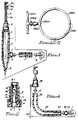
- Fig. 1 illustrates one preferred form of minisprinkler device operated with the P.H.T. method and formed for direct insertion and support in the soil adjacent to a tree or another area to be irrigated.
- a receptacle is in the form of a spike 1 having a sharp point 1a for ground insertion and enclosing a hollow chamber 2 having a square cross section for retention of water.
- the shape and dimensions of the container are determined by the particular application and can be of any practical volume.
- a practical dimension would be as a rectangular cross section 2,54 x 2,54 cm (1" x 1") with a length of 15,2 - 30,5 cm (6" - 12"). It is formed of a suitable rigid material, preferably of rigid, molded plastic, such that pressure increase within its hollow space will cause it to become slightly rounded and thus increase its volume.
- the container is provided with an inlet opening 3 and outlet 4.
- the inlet opening is fitted with a compensating dripper or other flow control device 5 which is in turn connected to a hose or tube 6 of suitable length for connection by means of a fitting 7a to a water supply pipe 7.
- the outlet is connected to a preset pressure responsive valve 8 of the type illustrated in Fig. 2. This is then connected by means of tube 9 having a small diameter bore 9a to a spray means 10 in which water is pulsed through nozzle 10a against a deflector 10b.
- the spray means may be of any suitable type such as a finger spray or a rotary spray or like where a large diameter spray area is desired.
- FIG.2 A preferred type of preset pressure responsive valve 8 which is especially effective in being quickly responsive to fluctuations in pressure is illustrated in Fig.2.
- Fig. 2 illustrates the structure of such preset pressure responsive valve 8 which includes three parts: an outer casing 11, an insert 12 and an elastic sleeve 13 made of rubber or the like, which surrounds and fits snugly the outside wall of insert 12.
- the outer casing and the insert are preferably formed of plastic material. These are concentric and preferably cylindrical.
- Insert 12, as shown, is in the shape of an inverted cup like member open at the bottom with its side walls surrounded by and engaged by sleeve 13.
- Elastic sleeve 13 is formed with a rib 13a, which is engaged in a slot 14 made in the insert 12, which is formed with a widened portion at the bottom to accommodate the slot and engage the rib portion of the elastic sleeve.
- the angular flat portion of the sleeve serves as a gasket between outlet casing 11 and insert 12.
- the bottom portion of insert 12 which is not engaged by the sleeve is cemented or force-fitted to the bottom portion of casing 11 as shown.
- Casing 11 and insert 12 are made of rigid material and are cemented together and provide a liquid inlet 15 and outlet 16.
- Insert 12 has one or more perforation 17 in its side wall.
- a critical pressure P1 the openings will be enclosed by elastic sleeve 13 which surrounds the insert tightly.
- pressure of liquid within the insert 12 is increased above a critical pressure P1, the pressure forces elastic sleeve 13 to expand in an expanding space 18 between casing 11 and insert 12.
- Perforations 19 in the casing 11 connect expanding space 18 with the external surroundings of the preset pressure responsive valve 8 allowing for fluids, namely, external air, to flow into the expanding space 18 and permitting the elastic sleeve to expand into the space.
- valve 8 When valve 8 opens and a liquid flows through the valve, elastic sleeve 13 expands, pressing against perforations 19 and against the fluid surrounding elastic sleeve 13 increasing its pressure and forcing it to flow out through outlet 16 where it is mixed and ejects with the liquid that flows through the valve 8.
- Inlet 15 is designed to snap on the outlet 4 of spike 1 in Fig. 1.
- Outlet 16 is designed so that rigid tube 9 in Fig. 1 can be snapped to it.
- water from the irrigation tube 7 flows through hose 6 and pressure compensated dripper 5 at a low continuously controlled flow Q2 to spike 1 in which it is being accumulated and its pressure is increased to a critical pre-designed pressure P1 at which elastic sleeve 13 of preset pressure responsive valve 8, which is connected to outlet 4 of spike 1, expands, and allows water to flow out from the spike 1 through preset pressure responsive valve 8 to a small sized inside diameter tube 9.
- Friction loss at tube 9 forces elastic sleeve 13 to widely expand, allowing for a high flow Q1 of water to be ejected from spike 1 through preset pressure responsive valve 8 and tube 9.
- the high flow ejected from the spike flows through nozzle 10a of a spray device 10 and spreads by deflector 10b over large designated area.
- valve 8 Due to the quick response of the preset pressure responsive valve 8, a "Water Hammer” is created which increases the pressure and velocity of the ejected water.
- fluid namely air
- valve outlet 16 When valve 8 close and opens itself, fluid namely air, flows into the casing 11 and out through the valve outlet 16 at pulses mixing with the liquid that flows through the valve.
- a conventional spring loaded normally closed valve may be used instead of the elastic sleeve type of valve described above.
- Fig. 3 describes an alternative manner of installing the device shown in Fig. 1 in which the spike container is divided into two sections 1b and 1c which are designed to encircle and engage the circumference of water conduit 6a which in effect passes through the container and may be engaged at spaced intervals by additional spike units of the same type.
- a compensating dripper 5a is inserted into opening 3a in the conduit positioned in the upper section as shown, and a controlled flow of water is passed into the chamber 2a and passed through outlet 4a into valve 8a and tube 9a as described above with respect to Fig. 1.
- the two sections are secured to the conduit by cementing or otherwise and to ensure against leakage a pair of gasket rings 21 may be cemented in place as shown.
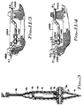
- Fig. 4 illustrates a pulsating minisprinkler in which the container, instead of being in the form of a spike, utilized to support a sprinkler or similar unit, is in the form of a flexible tube 22 which is connected to water supply 7 by means of a suitable fitting and in turn to a compensating dripper 24 and by means of another fitting to inlet 25 of the tube and the tube is connected at its outlet 26 by means of fitting 27 to valve 28.
- the function of the device is similar to that described with respect to Fig. 1 and 2. and support for the device of Fig. 4 is provided by means of a rod 30 or similar member which is affixed at its upper end to the valve and may be inserted into the ground as shown, to elevate the tubular container.
- Fig. 5 illustrates a pulsating device as shown in Fig. 1 where a small receptacle 31 which is formed of semi-rigid or flexible material containing air is placed within the receptacle to permit trapped air to increase the ejected amount of liquid in each pulse.
- Fig. 6 illustrates a pulsating device as shown in Fig.1, where the pressure compensating dripper of Fig. 1 is replaced by a small nozzle 5 which controls flow into the receptacle.
- a nozzle can be applied in place of the drippers shown in Figures 3 and 4.
- Fig. 7 illustrates a pulsating device with a mechanical obstacle in the form of a ball 32 which floats with the pressure of liquid that flows through the valve 8.
- the ball is incorporated within the outlet structure of the valve in Fig. 2.
- the ball 32 is placed within a compartment formed by an inner ring 33 provided with an opening 34 and a fitting 35 also provided with an outlet opening 36.
- Fig 8a and 8b illustrates the pumping action described above with arrows x in 8b showing the direction of flow of the secondary fluid, which as shown in Fig. 2 enters perforations 19 and fills space 18 confined between elastic sleeve 13 and the outer casing 11 during each pulse when the valve remains closed.
- the sleeve expands to the position shown in Fig. 8a . This causes the closure of perforations 19 and forces the fluid from space 18 and out between the elastic sleeve and the casing out through outlet 16 to become intermingled with the main fluid.
- the secondary fluid may be gas, such as air.
- Fig. 9 illustrates two types of pulsating valves by which a low continuous flow is converted to a high pulsating flow.
- Type A is a normally closed pulsating valve and type B is a normally open valve.
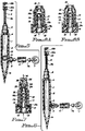
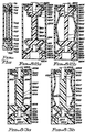
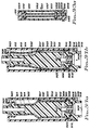
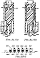
- Fig 9/1 illustrates a normally closed pulsating valve type A.
- the valve consists of elastic tube 9101, casing 9102 and insert 9103.
- Insert 9103 has a fluid inlet 9104 and fluid outlet 9105.
- Casing 9102 has a port 9106 through which space 9107 surrounding the elastic tube 9101 is vented.
- Insert 9103 has a barb 9108 for holding the elastic tube 9101 at a fixed place.
- Insert 9103 has an opening 9109 which can be used for supporting the valve on a rod.
- Insert 9103 at its inlet 9104 has an opening in the shape of a cylinder 9110 plugged at its end 9111 and having perforations 9112 at its circumference.
- insert 9103 At its outlet 9105 insert 9103 has an opening in the form of a cylinder 9113 plugged at its end 9114 and having perforations 9115 at its circumference.
- Section 9116 of insert 9103 and step 9117 are made for connecting casing 9102 to insert 9103.
- Outside diameter 9118 of insert 9103 allows the valve to be connected with its outside diameter at its inlet 9104 to a pipe or a fitting.
- Fluid inlet 9104 has also an opening in the shape of a casing 9119 for a flow control type B [please see Fig. 22 ] in which a tube 9120 can be installed for controlling the flow Q.0 into the valve.
- Center section 9121 of insert 9103 has an outside diameter smaller than barb 9108.
- Section 9122 of insert 9103 has an outside diameter smaller than section 9121.
- Section 9123 of insert 9103 has an outside diameter larger than section 9122 and it is made for holding elastic tube 9101 at a fixed position.
- Section 9124 of insert 9103 is made for connecting a spraying device by fitting it to the outside diameter of section 9124 or by inserting it into its inside diameter.
- Elastic tube 9101 has an inside diameter smaller than the outside diameter of insert 9103 at sections 9121 and 9122.
- Fig. 9/1a shows the normally closed pulsating valve type A at its closed position.
- Elastic tube 9101 surrounds tightly insert 9103 sealing perforations 9112 preventing a fluid to flow from inlet 9104 through the valve to outlet 9105.
- Fig. 9/1b shows the normally closed pulsating valve type A at its pulsating stage.
- a fluid at a low controlled flow Q.0 controlled by a flow control 9120 [or by another type of flow control which can be a pressure compensated dripper, a dripper or a nozzle connected to inlet 9104] flows into opening 9110 at the fluid inlet 9104 of the pulsating valve.
- the pressure P.1 of the fluid at opening 9110 forcing elastic tube 9101 to expand and its diameter to increase to D.1 in response to the pressure P.1.
- the fluid then flows through perforations 9112 to the space 9125 created between the outside diameter 9121 of insert 9103 and the inside diameter D.1 of elastic tube 9101. At this stage the fluid flows at a flow Q.0 through the small open cross section created at space 9125 around section 9121.
- the inside diameter of elastic tube 9101 is increasing to D.2.
- a volume dV of fluid accumulates between the elastic tube 9101 inside diameter D.2 and the insert outside diameter at section 9121.
- the large cross section of space 9125 created between outside diameter of insert 9103 and the inside diameter D.2 of elastic tube 9101 allows the volume dV of the fluid to flow at a high rate Q.1 through sections 9121 and 9122 perforations 9115 and opening 9113, out through the fluid outlet 9105.
- the volume dV of the fluid in space 9125 decreases
- the pressure in space 9125 decreases
- the inside diameter of elastic tube 9101 decreases, and becomes smaller than the outside diameter of insert 9103 at section 9121.
- the elastic tube 9101 surrounds tightly perforations 9112 closing the fluid inlet 9104 and terminating one pulsating cycle.
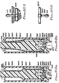
- Fig. 9/2 illustrates a normally closed pulsating valve type A with its outlet formed into a deflector for controlling the pattern of the ejected flow.
- the valve consists of elastic tube 9201, casing 9202 and insert 9203.
- Insert 9203 has a fluid inlet 9204 and fluid outlet 9205.
- Casing 9202 has a port 9206 through which space 9207 surrounding the elastic tube 9201 is vented.
- Section 9208 of insert 9203 has a large outside diameter formed as a barb for holding elastic tube 9201 at a fixed place.
- An opening 9209 at the bottom of insert 9203 can be used for supporting the valve on a rod.
- Fluid inlet 9204 has an opening in the form of a cylinder 9210 plugged at its end 9211 and having perforations 9212 at its circumference.
- Insert 9203 is formed in the shape of a deflector 9213.
- Section 9214 and step 9215 of insert 9203 are made for connecting casing 9202 to insert 9203.
- Section 9216 of insert 9203 has an outside diameter that can be used to connect the valve with its outside diameter to a pipe or a fitting.
- Fluid inlet 9204 has also a space 9217 which can be used for installing a flow control type B in which a tube 9218 or the same can be installed inside insert 9203 for controlling the flow of fluid Q.0 into the pulsating valve.
- a flow control, a dripper, a pressure compensated dripper or any type of means for controlling the flow of a fluid into the pulsating valve can be connected to the fluid inlet 9204 either by connecting it to the outside diameter of section 9216 or by its inside diameter.
- Center section 9219 of insert 9203 has an outside diameter smaller than section 9208.
- Section 9220 of insert 9203 has an outside diameter smaller than section 9219.
- Elastic tube 9201 has an inside diameter smaller than the outside diameter of insert 9203 at sections 9219 and 9220.
- Fig. 9/2a shows the normally closed valve type A at its closed position.
- Fig. 9/2b shows the normally closed pulsating valve type A at its pulsating stage.
- the elastic tube 9201 inside diameter is increasing to D.2.
- a volume dV of fluid is accumulating between the elastic tube 9201 inside diameter D.2 and the insert outside diameter at section 9219.
- the large cross section created between the insert 9203 at section 9219 and the elastic tube 9201 inside diameter D.2 allows the volume dV of the fluid to flow at a high rate Q.1 from space 9221 through sections 9219 and 9220 out through the valve outlet 9205 created around insert 9203 when elastic tube 9201 expands.
- the fluid then flows through port 9206 in casing 9202 to the deflector 9213 which controls the pattern of the ejected fluid.
- the volume of fluid dV in space 9221 decreases
- the pressure of the fluid inside space 9221 decreases
- the elastic tube 9201 inside diameter decreases and becomes smaller than the outside diameter of insert 9203 at section 9219
- the elastic tube 9201 surrounds tightly perforations 9212 preventing the fluid from flowing out from cylinder 9210, closing the "valve" and terminating one pulsating cycle.
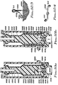
- Fig. 9/3 a illustrates a "normally open pulsating valve" type B consisting of elastic tube 9301, casing 9302, inlet fitting 9303, and outlet fitting 9304.
- Inlet fitting 9303 has a fluid inlet 9305 and a port 9306 through which space 9307 surrounding elastic tube 9301 is pressurized. Outside diameter of inlet fitting 9303 at section 9308 is formed as a barb. Sections 9309 and step 9310 of the inlet fitting 9303 are formed for connecting casing 9302 to inlet fitting 9303.
- Outlet fitting 9304 has a fluid outlet 9311 and a barb 9312. Barbs 9308 and 9312 are made for holding elastic tube 9301 at a fixed place.
- fluid with a controlled low flow Q.0 and a pressure P.1 enters fluid inlet 9305 and then flows through the elastic tube 9301.
- the fluid also enters through port 9306 to space 9307 pressurizing space 9307 with the same pressure P.1 of the fluid at inlet 9305.
- a pressure drop dP is created along the elastic tube 9301 and the pressure P.1 inside elastic tube 9301 at its inlet 9313 drops to P.2 at section 9314 of the elastic tube 9301.
- the pressure surrounding the elastic tube 9301 is P.1 which is higher than the pressure P.2 inside the elastic tube 9301 at section 9314 and as a result, elastic tube 9301 at section 9314 becomes flat, closing the valve.
- the normally open pulsating valve can be produced also with a center rod supported by ribs where inlet fitting, outlet fitting, center rod, the ribs and the barbs are produced as one insert unit.
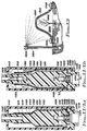
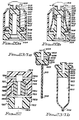
- Figs. 10 illustrate a self cleaning filter having a pulsating valve structure.
- this valve is the same as pulsating valve type A described in Figs. 9/1 in which part of the elastic tube section is perforated creating a "screen".
- the valve consists of elastic tube 10101, casing 10102, and insert 10103.
- Insert 10103 has a fluid inlet 10104 and a fluid outlet 10105.
- Casing 10102 has a port 10106 through which space 10107 surrounding elastic tube 10101 can be vented.
- Port 10106 is also the filtered fluid outlet.
- Insert 10103 has a barb 10108 for holding elastic tube 10101 in a fixed position.
- Insert 10103 has a hole 10109 by which the valve can be supported on a rod.
- Fluid inlet 10104 has a hole in the form of a cylinder 10110 plugged at its end 10111 and having perforations 10112 at its circumference.
- Fluid outlet 10105 has an opening in the form of a cylinder 10113 plugged at its end 10114 and having perforations 10115 at its circumference.
- Section 10116 of insert 10103 and step 10117 are formed for connecting casing 10102 to insert 10103.
- Outside diameter of insert 10103 at section 10118 can be used for connecting the valve with its outside diameter at the fluid inlet to a fluid supply pipe or fitting.
- Fluid inlet 10104 has also an opening in the form of a casing 10119 for a flow control type B and as an option the flow through the valve can be controlled by elastic tube 10120.
- Center section 10121 of insert 10103 has an outside diameter smaller than section 10108.
- Section 10122 has a larger diameter than section 10121 and smaller than section 10108.
- Section 10123 has an outside diameter smaller than that of section 10121 and section 10124 has an outside diameter larger than section 10123.
- Outside or inside diameters of section 10125 can be used for connecting a deflector to the valve.
- Elastic tube 10101 surrounding insert 10103 at part of section 10121, between perforations 10112 and section 10122 is perforated forming a "screen".
- Elastic tube 10101 inside diameter is smaller than the outside diameter of the insert at sections 10121 and 10123 and it surrounds tightly the insert 10103.
- Fig. 10a shows the filter valve at its closed position.
- Fig. 10b shows the filter valve at its filtering stage.
- Figs. 11 illustrate different types of pumps having a pulsating valve structure and different applications of these pumps.
- Figs. 11/1 illustrate a fluid injection pump.
- the injection pump has a similar construction to that of a pulsating valve type A shown in Figs. 9/1 with the port in the casing locating opposite the perforations at the valve fluid inlet.
- the injection pump consists of elastic tube 11101, casing 11102 and insert 11103.
- Insert 11103 has a fluid inlet 11104 and fluid outlet 11105.
- Casing 11102 has a port 11106 through which a fluid surrounding the pump can enter into space 11107 surrounding elastic tube 11101.
- Section 11108 of insert 11103 has a large outside diameter in the form of a barb for holding elastic tube 11101 in a fixed position.
- Insert 11103 has an opening 11109 by which the pump can be supported on a rod.
- Fluid inlet 11104 has an opening in the form of a cylinder 11110 plugged at its end 11111 and perforations 11112 at its circumference.
- Fluid outlet 11105 has an opening in the shape of a cylinder 11113 plugged at its end 11114 and having perforations 11115 at its circumference.
- Section 11116 of insert 11103 and step 11117 are made for connecting casing 11102 to insert 11103.
- Outside diameter of section 11118 can be used as an option for connecting a fluid supply pipe or fitting to the pump.
- Fluid inlet 11104 has an opening in the form of a casing 11119 for flow control type B by which an elastic tube 11120 can be used for controlling the flow into the pump.
- Center section 11121 of insert 11103 has an outside diameter smaller than its diameter at section 11108 and larger than its diameter at section 11122. Inside and outside diameters of the insert 11103 at section 11123 can be used for connecting a pipe or a fitting for delivering the discharged fluid from the pump.
- Fig. 11/1a shows an injection pump at the stage in which the "pulsating valve" is closed and a fluid M which surrounds the pump enters its casing 11102 through port 11106 filling space 11107.
- Fig. 11/1b shows the stage at which fluid N enters the pump at a flow Q.1 from its fluid inlet 11104 causing elastic tube 11101 to expand, pressing elastic tube 11101 against casing 11102 sealing part 11106 and increasing the pressure of the fluid M in space 11107.
- Fluid M then flows through the open space 11124 created between section 11122 of the insert 11103 and the elastic tube 11101 which is forced to expand and increase its inside diameter in response to the pressure of fluid N that flows through the pump in pulses.
- Figs. 11/2 illustrate a "fluid driven pump” consisting of a pulsating device type A in which its casing has one port through which fluid M enters the pump, when the pulsating valve, is at its closed position and a second port through which fluid M is discharged from the pump at a higher pressure, when a fluid N flows through the pulsating valve forcing it to pulsate.
- the pump consists of elastic tube 11201, casing 11202 and insert 11203.
- Insert 11203 has a fluid N inlet 11204 and a fluid N outlet.
- Casing 11202 has a port 11206 through which fluid M surrounding the pump can enter space 11207 surrounding elastic tube 11201.
- Casing 11202 has a second port 11208 trough which fluid M can be ejected from space 11207.
- Insert 11203 has a hole 11209 by which the pump can be supported on a rod.
- Fluid N inlet 11204 has an opening formed in the shape of a cylinder 11210 plugged at its end 11211 and having perforations 11212 at its circumference.
- Fluid N outlet 11205 has an opening in the form of a cylinder 11213 plugged at its end 11214 and having perforations 11215 at its circumference.
- Section 11216 of insert 11203 and step 11217 are made for connecting casing 11202 to insert 11203.
- Section 11218 of insert 11203 can be used for connecting the pump by its outside diameter to a fluid N pipe supply or fitting.
- Fluid N inlet 11204 has also a hole 11219 in the form of a casing for a flow control type B and the flow Q.1 of fluid N into the pump can be controlled by an elastic tube 11220.
- Section 11221 of insert 11203 has a large outside diameter in the form of a barb for holding the elastic tube 11201 at a fixed place.
- Center section 11222 has an outside diameter smaller than of section 11221.
- Section 11223 has an outside diameter smaller than that of section 11222, and section 11224 has an outside diameter larger than that of section 11223.
- Fig. 11/2a shows the pump at the stage in which the "pulsating valve" is at its closed position and fluid M flows through port 11206 into space 11207 filling it up.
- Fig. 11/2b shows the pump at the stage in which fluid N enters the pump through the valve fluid N inlet 11204, causing it to pulsate.
- Elastic tube 11201 expands pressing against casing 11202, sealing port 11206, pressurizing the fluid in space 11207 and forcing it to eject through port 11208 at a flow Q.2 while fluid N is ejected through the valve fluid N outlet at a pulsating flow.
- the system consists of an injection pump 11/1 connected to water supply pipe 11302, valve 11302 connected to outlet of injection pump 11/1, and a pipe 11303 connected to outlet of valve 11302.
- Water M in the reservoir is at elevation 11304 and it flows by gravity at a rate of Q.2 into the pump through its port 11106.
- Fig. 11/4 illustrates A pump 11/2 that is pumping water from a reservoir M when water from source N flows through the pump.
- the installation consists of a pump 11/2, check valve 11401 connected to fluid N outlet of the pump. Fluid N water supply pipe 11402 fluid N discharging pipe 11403. Check valve 11404 connected to port 11208 of pump 11/2 [shown in Fig. 11/2 ] and fluid M discharging pipe 11405 connected to the outlet of check valve 11404. Water in reservoir M is at elevation 11406 and it flows by gravity at a rate of Q.2 into port 11206 of pump 11/2 filling space 11207 [see Fig. 11/2 ] of the pump when the "pulsating valve" is at its closed position.
- Fluid N that flows from pipe 11402 through pump 11/2 valve 11401 and fluid N discharge pipe 11403 causing the valve to pulsate and fluid M to eject at elevated pressure from space 11207 of pump 11/2 through its port 11208, check valve 11404 to M discharging pipe 11405.
- Figs. 11/5 illustrate a soaping device consisting of a "fluid driven pump” 11/2 with a liquid soap container 11501 connected to port 11208 of the pump. [please see also Fig. 11/2.].
- the device is connected to a faucet which supplies water N to the fluid N inlet to the valve.
- Container 11501 is filled up with liquid soap.
- Fig. 11/5a shows the valve at its closed position. Liquid soap from container 11501 flows through port 11206 of pump 11/2 into space 11207 of pump 11/2.
- Fig. 11/5b shows the device at its soaping position.
- Water N flows through the pump 11/2 causing the "pulsating valve" to pulsate.
- Air enters port 11206 of pump 11/2 and flows out through the liquid soap at space 11207 of the pump and through port 11208 into container 11501 through the liquid soap 11502 in container 11501 converting the liquid soap to foam which flows by gravity to the pump 11/2 outlet 11205 where it is mixed and ejected with the water that flows at a high pulsating flow.
- the pumps described in these figures have the same construction as pulsating valves type A as described is Fig. 9 with the port in the casing located opposite of the perforations at the inlet to the "receptacle container" of the pulsating valve.
- the perforations at the inlet to the "receptacle container” are located at one of its ends and the fluid flows out from the container at its other end.
- the volume of fluid in the "receptacle container" is zero and the elastic tube surrounds tightly the insert.
- a fluid M which surrounds the valve enters the casing of the valve through its port.
- the elastic tube expands, pressing against the port at the casing, sealing it and compressing fluid M against the casing wall.
- Fluid driven pump in this pump as described in which fluid M enters the casing of the pump at one port is pressurized and flows out from the pump through a second port in the casing, when fluid N enters the pump inlet, it causes it to pulsate and become ejected through the pump outlet.
- pump 11/2 When pump 11/2 is installed in a reservoir with water M.
- water N flows through the pump and causing it to pulsate, water M enters the pump through one port in its casing and flows out at a higher pressure from a second port at the casing.
- 11/5a soaping device functions as a "water driven compressor” with a liquid soap container connected to the air outlet at the casing of the pump.
- the device is connected to a faucet and when water flows through the liquid soap, it converts it to foam which flows by gravity to the pump outlet where it is mixed and eject with the water that flows out from the pump at high pulsating flow.
- Fig. 12 illustrates pulsating low flow: spray heads, minisprinklers, rotating sprinklers and driplines for irrigation, connected to a lateral by means a pulsating valve.
- Fig. 12/1 shows a pulsating spray head such as shown in Fig.9/1 or Fig. 9/2 connected by means of a rigid riser 12101 and Tee 12102 to a rigid pipe 12103.
- a low flow Q.2 of water flows from pipe 12103 through riser 12101 through a flow control installed inside the pulsating valve 9/1 at which the low continuous flow Q.2 is converted to a high pulsating flow Q.1 which ejects through a deflector that can be connected at the outlet from pulsating valve 9/1 or which is formed at the outlet of pulsating valve 9/2.
- the high ejected flow Q.1 that flows through the deflector is sprayed to a large designated area.
- FIG. 12/2 shows a pulsating spray head such as shown in Fig.9/1 or Fig. 9/2 installed with its outlet below its inlet and connected by means of a riser 12201 and a Tee 12202 to pipe 12203.
- a pulsating spray head such as shown in Fig.9/1 or Fig. 9/2 installed with its outlet below its inlet and connected by means of a riser 12201 and a Tee 12202 to pipe 12203.
- a riser 12201 and a Tee 12202 to pipe 12203 Such an arrangement can be used for example in green houses.
- Fig. 12/3 shows a pulsating spray head such as shown in Fig. 9/1 or Fig. 9/2 connected to a flexible tube 12301 by means of flexible tube 12302. Pulsating spray head 9/2 is supported with a rod 12303 which is inserted into the ground 12304.
- Fig. 12/4 shows pulsating spray heads such as shown in Fig.9/1 or Fig. 9/2 connected to the outlets of rotating sprinkler 12401.
- the pulsating valve can be also installed at the inlet to the sprinkler head.
- Fig. 12/5 Shows a pulsating drip tube in which irrigation tube 12501 supplies irrigation water through a pressure compensated dripper 12502 which supplies a low controlled flow Q.2 to a pulsating valve 12503 at which the low flow Q.2 that enters the pulsating valve from the dripper 12502 is converted to a high pulsating flow Q.1 that flows through the fitting 12504 to tube 12505 and out through perforations 12506.
- the high pulsating flow Q.2 that flows through the perforations 12506 allows the size of perforations 12506 to be very large yet the amount of water that flows through each perforation 12506 is very small and equal to the amount of water that flows through dripper 12502 divided by the number of perforations in the tube 12505.
- Fig. 13 illustrates a plant frost control system consisting of a screen 13101 surrounding a plant 13102 and a pulsating sprinkler 13103 connected with riser 13104 to a water supply pipe 13105.
- Screen 13101 is floating and supported by plant 13102 and held at a fixed place by a pile of dirt 13106.
- pulsating sprinkler 13103 a layer of water 13107 is held by the screen 13101 which at low temperature of 32 degrees F. is converted to ice forming an "Igloo" which isolates a volume of air 13108 which surrounds the plant 13102.
- the theory by which this system operates is exactly the same theory by which the Eskimo igloo operates.
- the invention describes a method for building an igloo which surrounds the item that need to be protected from frost.
- the frost protection system according to this method consists of 2 basic elements:
- the sheath can be made of any material that can be wetted. Water can be held by the sheath in different ways:
- the "igloo" should be completely sealed. An opening in the “igloo” will allow wind to flow through and the warm air inside the “igloo” will be replaced by cold air from outside. For this purpose the sheath has to be installed in such a way that it will be completely wet by the sprayer.
- Plants have some specific requirements: Plants need light and they cannot be covered for a long period of time by a material that blocks the light.
- a screen can be used.
- a screen By using a screen the space surrounding the plant is vented and has light and at the end of the frost the ice on the screen melts. The light can immediately penetrate through the screen and so does fresh air.
- screens By using screens the plants can be covered and removed a substantial long time before frost is expected and long time after the frost forecasting time.
- the screens can be durable, disposable or degradable and of a suitable degree of porosity or opening size.
- floating screens can be used. Such screens are supported by the plants themselves. Other supporting means can be used too if needed.
- the pulsating sprayer in order to wet the screen any type of sprinkler can be used yet a sprinkler with a high rate of water application will create a heavy layer of ice which will cause the screen to collapse.
- Sprinklers can apply small quantities of water when controlled by a timer. During frost if the sprinklers do not operate, the water freezes in the sprinklers' risers and nozzles and as a result operating high flow sprinklers in cycles is not a practical solution. In a large range, in order to protect all the plants, all the screens covering all the plants should be wetted at the same time, all the time. Most irrigation systems cannot operate this way because of their high flow. Most sprinklers systems operate in cycles. At the end of each irrigation cycle the water from the pipes, or from some of them, drains through the sprinklers nozzles and a certain time is wasted during the time in which the pipes are filled up again.
- the pulsating sprinklers provide a solution for those problems. They can apply a low application of water to each screen, all the pulsating sprinklers can be operated at the same time and controlled by one valve, the pipes do not drain and no time is wasted for filling back the pipes.
- Such a system can be connected to a temperature sensor which automatically operates the system at a preset temperature.
- the pulsating sprinklers can be installed inside or outside the "igloo” provided they fully wet the screens.
- a pulsating sprinkler installed inside the "igloo” has a few advantages:
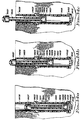
- Fig. 14 illustrates a self cleaning low flow pulsating pop up sprinkler consisting of casing 14101, casing's fluid inlet fitting 14102, casing's outlet fitting 14103, sliding guide 14104 riser 14105, "O ring” 14106, pulsating low flow sprayer 14107 and sleeve 14108.
- Sliding guide 14104 is a filter in the form of a cylinder with the riser 14105 fits tightly its open end 14109.
- Casing outlet fitting 14103 has an inside diameter 14110 larger than the outside diameter of riser 14105 and a space 14111 is created at the outlet fitting between its inside diameter 14110 and outside diameter of riser 14105.
- the outside diameter of sliding guide 14104 and of "O ring" 14106 is smaller than the inside diameter of casing 14101.
- Fig. 14a shows the pop up pulsating sprayer at its low position.
- Fig. 14b shows the pop up sprayer at its rising stage.
- the pressure in space 14115 at this stage is lower than the preset pressure P.0 of the pulsating spray head 14107 and no water flows through the normally closed pulsating spray head 14107.
- Fig. 14/c shows the pulsating pop-up sprayer at its open position.
- sliding guide 14104 is pressing "O ring" 14106 against the bottom of outlet fitting 14103, sealing space 14111.
- the pressure in space 14115 increases to P.2 higher than the preset pressure P.0 of the pulsating sprayer and fluid flows through filter 14104 to riser 14105 and to pulsating sprayer 14107 at a low flow Q.0 wetting a large designated area.
- fluid at a flow Q.2 flows through space 14113 flushing the filter 14104 and ejecting the flushing fluid through the open space 14111.
- Fig. 15 illustrates by diagram and structure a method and devices for controlling different outlets connected to the same pipe and operate separately by changing the pressure in the pipe.
- Fig. 15/1 shows a "limiting valve” consisting of a normally closed valve which opens itself at a preset pressure P.0 connected to the outlet of a normally open valve which closes itself at a preset pressure P.C. higher than P.0
- Fluid can flow through such a "limiting valve” from its fluid inlet 15101 to its fluid outlet 15102 only when its pressure at the fluid inlet 15101 is at a range of P.0. to P.C. At any pressure lower than P.0. at the fluid inlet 15101 to the "limiting valve".
- the normally closed valve eliminates the fluid from flowing through the valve.
- the normally open valve eliminates the fluid from flowing through the valve.
- Fig. 15/2 is a schematic drawing showing an example of a system consisting of 6 groups of outlets connected to the same pipe and operating separately by changing the pressure in the pipe.
- Group 15204 consists of "limiting valve” 15/1 with pressure opening range of 172 to 207 kPa (25 to 30 psi) and connected to outlet 15207 from pipe 15203.
- Group 15208 consists of "limiting valve” 15/1 with pressure opening range of 207 to 241 kPa (30 to 35 psi) connected to outlet 15209 from pipe 15203.
- Group 15210 consists of "limiting valve” 15/1 with opening range of 172 to 276 kPa (25 to 40 psi) connected to outlet 15211 from pipe 15203.
- Group 15212 consists of normally closed valve with a preset opening pressure of 276 kPa (40 psi) connected to outlet 15213 from pipe 15203. The pressure in pipe 15203 is controlled by valve 15214.
- Figs. 17 illustrate a normally closed hydraulic valve consisting of elastic tube 2101, casing 2102 and insert 2103.
- Insert 2103 has a fluid inlet 2104 and a fluid outlet 2105.
- Casing 2102 has a port 2106 through which space 2107 surrounding elastic tube 2101 can be pressurized or vented.
- Insert 2103 has large outside diameter in the form of barbs 2108 and 2109 for holding the elastic tube 2101 at a fixed place.
- Insert 2103 has a center rod 2110, supporting ribs 2111 at inlet 2104 and ribs 2112 at outlet 2105. Section 2113 of rod 2110 has a diameter larger than the inside diameter of elastic tube.
- barbs as used herein and elsewhere in the specification and claims refers to transverse projections on the insert which serve to define the diameter of the insert and retain the tubular elastic member. In most cases the tube ends will be held in position by the elastic tension but where necessary cementing may also be used at such points.
- Fig 17a shows the normally closed hydraulic valve at its normally closed position. At this position elastic tube 2101 surrounds tightly rod 2110 at its large diameter portion 2113, eliminating from a fluid to flow from the valve fluid inlet 2104 to the fluid outlet 2105.
- Fig.17b shows the normally close hydraulic valve at its open position.
- the pressure of the fluid at the fluid inlet 2104 is higher than the preset pressure P.0 of the valve, and the pressure of the fluid is forcing the elastic tube 2101 to expand, its inside diameter increases and becomes larger than the outside diameter of the center rod 2110 at section 2113, allowing the fluid to flow from inlet 2104, bypassing ribs 2111 through the elastic tube 2101 and the space 2114 created around the rod 2110 at its large section 2113, bypassing ribs 2112 and out through outlet 2105.
- the valve can be closed by pressurizing space 2107 or by decreasing the pressure at the fluid inlet 2104 bellow the preset pressure P.0 of the valve.
- This valve has the same construction as that of a normally open hydraulic valve with the elastic tube surrounding a center rod. Part of the rod has a diameter larger than the inside diameter of the elastic tube. At its normally closed position the elastic tube surrounds tightly the large portion of the rod preventing fluid from flowing through the valve.
- This hydraulic valve will open itself when the port in the casing is vented and the pressure at the valve inlet is higher than a preset pressure P.0 The valve will close itself when the pressure at the inlet is reduced to a pressure lower than P.0 or when the space surrounding the elastic tube is pressurized through the port in the casing.
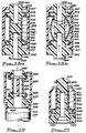
- Fig.18 illustrates a normally closed valve consisting of elastic tube 3101, casing 3102, and insert 3103.
- Insert 3103 has a fluid inlet 3104 and a fluid outlet 3105 .
- Casing 3102 has a port 3106 through which space 3107 surrounding the elastic tube is vented.
- Insert 3103 has barbs 3108 and 3109 by which elastic tube 3101 is held its place.
- Fluid inlet 3104 has a hole in the form of a cylinder 3110 plugged at its end 3111 and has perforations 3112 at its circumference.
- Fluid outlet 3105 has a hole in the form of a cylinder 3113 plugged at its end 3114 and has perforations 3115 at its circumference.
- Insert 3103 has an outside section 3116 and a step 3117 by which casing 3102 is connected to insert 3103.
- insert 3103 has an outside diameter 3118 that can be used for connecting the pulsating valve at its outside diameter to a fluid supply pipe or a pipe fitting.
- Outlet fitting 3105 has an outside diameter 3119 that can be used for connecting the pulsating valve at its outside diameter to a sprinkler or any other device.
- Center section of insert 3103 has an outside diameter 3120 larger than inside diameter of elastic tube 3101 and elastic tube surrounds tightly the insert 3103.
- Fig. 18a shows the normally closed valve at its normally closed position.
- elastic tube 3101 surrounds tightly the insert 3103, closing perforations 3112 and 3115, eliminating fluid to flow from the fluid inlet 3104 to the fluid outlet 3105 keeping the valve in a closed position.
- Fig. 18b shows the valve at its open position.
- Normally closed hydraulic valve With its port in the casing vented can be used.
- Normally closed valves can also consist of two elements, an insert, and elastic tube surrounding tightly the insert.
- Such a valve comprises an insert in which each of its ends has a cylindrically shaped hole perforated at its circumference and plugged at its end. Both ends are formed as barbs by means of which the elastic tube is held fixed.
- the center section of the insert has an outside diameter larger than the inside diameter of the elastic tube.
- the elastic tube surrounds tightly the center section of the insert and the perforation of the cylinders at the inlet and the outlet.
- the pressure at the inlet is P.2 higher than P.0, the fluid flows from the cylinder at the inlet through the perforation in its circumference to a space created between the outside diameter of the insert and the elastic tube to the perforations of the cylinder at the outlet then through the cylinder and out from the valve outlet.
- the casing is used to protect and support the elastic tube assembly.
- Insert 4103 comprises fluid inlet 4104, fluid outlet 4105, port 4106 through which space 4107 surrounding elastic tube 4101 is pressurized, barbs 4108 and 4109 by which elastic tube 4101 is held at a fixed place, a center rod 4110 supported by ribs 4111 at inlet 4104 and ribs 4112 at outlet 4105.
- Insert 4103 has an outside diameter 4113 by which a fluid supply pipe or fitting 4114 can be connected to the valve.
- Fig. 19 shows the valve at its normally open position in which a fluid can flow from the fluid inlet 4104, bypassing ribs 4111 through elastic tube 4101 around center rod 4110, bypassing ribs 4112 and out through fluid outlet 4105.
- the fluid has the same pressure as at the fluid inlet 4106.
- P.C preset pressure
- the force created by the fluid at space 4107 pressing on elastic tube 4101 outside diameter becomes larger than the force acting on elastic tube 4101 on its inside diameter and as a result the elastic tube 4101 surrounds tightly center rod 4110 eliminating from fluid to flow from inlet 4106 to outlet 4105 closing the valve.
- the valve will stay closed as long as the pressure of the fluid at inlet 4106 will be higher than a preset pressure P.C.
- This valve has the same construction as that of a normally open hydraulic valve with its pressurizing port connected constantly to a pressure source at the valve inlet.
- the elastic tube is exposed to the same pressure inside and outside its circumference and since the outside diameter of the elastic tube is larger than its inside diameter the force F.3 on the elastic tube from outside is larger than the force F.2 on the pipe from inside.
- the force differential d F F.3 - F.2 will cause the tube to become flat when it is larger than the resistance dF.0 of the tube to become flat at a certain preset pressure P.C according to the conditions described in formula (5).
- Insert 5103 has a fluid inlet 5104 and fluid outlet 5105.
- Casing 5102 has as port 5106 through which space 5107 surrounding elastic tube 5101 is vented.
- Insert 5103 has a barb 5108 by which elastic tube 5101 is held at a fixed place.
- Insert 5103 has a hole 5109 by which the valve can be supported on a rod.
- Fluid inlet 5104 has a hole in the form of a cylinder 5110 plugged at its end 5111 and having perforations 5112 at its circumference.
- Insert 5103 has a hole 5113 by which a deflector 5114 is connected to the valve.
- Insert 5103 has a section 5115 and a step 5116 by which casing 5102 is connected to insert 5103.
- Insert 5103 has at its center section an outside diameter 5117 smaller than the inside diameter of elastic tube 5101.
- Fig. 20a shows the valve at its closed position.
- Elastic tube 5101 surrounds tightly outside diameter 5117 of insert 5103 and perforations 5112 preventing fluid flow from the fluid inlet 5104 and perforations 5112 to the fluid outlet 5105.
- Fig. 20b shows the valve at its open position.
- the fluid will continue to flow through the valve and the deflector 5114 as long as the pressure of the fluid at inlet 5104 will be higher than the preset pressure P.0 of the valve.
- the valve consists of an insert surrounded tightly by an elastic tube and having a cylindrical hole at one end which is the inlet of fluid to the valve.
- the cylinder is plugged at its end and has perforations at its circumference communicating with the elastic tube. Outside diameter of the insert at the inlet section is formed as a barb for holding the elastic tube at a fixed place.
- outside diameter of the insert at its end, is the fluid outlet, from which the fluid flows, when the valve opens and the elastic tube expands, through the space created between the elastic tube and the insert.
- the fluid flows to a deflector connected to the insert end, which controls the pattern of the ejected fluid.
- the elastic tube has an inside diameter smaller than the outside diameter of the center section of the insert.
- Fig. 21 illustrates a normally closed spray head with a deflector being an integral part of the insert. The drawing shows the valve at its normally closed position.
- the valve consists of elastic tube 6101, casing 6102 and insert 6103.
- Insert 6103 has a fluid inlet 6104 and a fluid outlet 6105.
- Casing 6102 has a port 6106 through which space 6107 surrounding elastic tube 6101 is vented.
- Insert 6103 has a barb 6108 by which elastic tube 6101 is held at a fixed place.
- Insert 6103 has a hole 6109 by which the valve can be supported on a rod.
- Fluid inlet 6104 has a hole in the form of a cylinder 6110 plugged at its end 6111 and having perforations 6112 at its circumference.
- Section 6113 and step 6114 of insert 6103 are formed for connecting casing 6102 to insert 6103.
- Top of insert 6103 is formed in a shape of a deflector 6115.
- Center section of insert 6103 has an outside diameter 6116 larger than the inside diameter of the elastic tube 6101 and the elastic tabs 6101 surrounds tightly the insert 6103.
- the Figure shows the valve at its normally closed position.
- Elastic tube 6101 surrounds tightly insert 6103 at its outside diameter 6116 sealing perforations 6112 and eliminating fluid flow from the fluid inlet 6104 to the fluid outlet 6105.
- This normally closed spray head has the same construction as that of the valve described above, with the deflector being part of the valve itself.
- the deflector is created by different combinations of the insert and the elastic tube.
- Fig. 7/1a and 22 illustrates two types of flow controls.
- Fig. 7/1a illustrates flow control type A which has a similar construction to that of a normally open valve.
- the valve consists of elastic tube 7101, casing 7102, inlet fitting 7103 and outlet fitting 7104.
- Inlet fitting 7103 has a fluid inlet 7105 and a port 7106 through which space 7107 surrounding elastic tube 7101 is constantly pressurized at the same pressure of the fluid at the fluid inlet 7105.
- Inlet fitting has a barb 7108.
- Inlet fitting has also section 7109 and step 7110 for connecting casing 7102 to inlet fitting 7103.
- Outlet fitting 7104 has a fluid outlet 7111 and a barb 7112. Barbs 7108 and 7112 are formed for holding elastic tube 7101 at a fixed place.
- Elastic tube 7101 has a length and inside diameter such that at a certain nominal flow Q.0 a fluid can pass through the elastic tube 7101 without or with a negligible pressure drop along the tube.
- the force on the outside diameter of elastic tube 7101 becomes larger than the force on the inside diameter of elastic tube 7101 and as a result inside diameter of elastic tube 7101 between cross section 7113 at the inlet to elastic tube 7101 and cross section 7114 at the outlet from elastic tube 7101, decreases, preventing the flow of the fluid through the valve from increasing.
- the range of pressures P.3 at which this valve operates as a flow control depends on the dimensions and physical properties of the elastic tube 7101 as well as the pressure drop dP created in the elastic tube 7101. When the pressure P.3 of the fluid at the fluid inlet 7105 increases and becomes higher than a preset pressure P.C. the flow control will close itself.
- Fig. 7/1a shows the flow control at a position in which the pressure at the fluid inlet 7105 is lower than P.C. and the fluid is flowing through the valve at a controlled flow Q.0.
- Fig. 22 illustrates a flow control type B which operates at the same way flow control type A operates.
- Flow control type B consists of elastic tube 7201, casing 7202 and insert 7203.
- Insert 7203 has a fluid inlet 7204 and casing 7202 has a fluid outlet 7205.
- Casing 7202 has an inside diameter 7206 by which insert 7203 with its outside diameter 7207 is connected to the casing 7202.
- Casing 7202 has also a smaller inside diameter 7208 with slots 7209 at its inside circumference which at section 7210 are deeper than slots 7209.
- the casing 7202 has no slots and, casing 7202 has a hole in the form of a cylinder 7212 having an inside diameter smaller than in section 7211. Cylinder 7212 is plugged at its end 7213 and has perforations 7214 at its circumference which are also the fluid outlet 7205 of the flow control.
- negligible pressure drop is created along elastic tube 7201.
- the pressure inside elastic becomes lower than the pressure P.3 surrounding the elastic tube 7201 and as a result the elastic tube inside diameter decreases, eliminating from the nominal flow Q.0 to increase thus controlling the flow through the valve.
- the flow controls described have the same construction as the construction of a normally open valve in which the elastic tube has such dimensions, length and inside diameter, that when the pressure P.3 at the inlet increases, fluid flow through the tube and a pressure drop dP is created in the elastic tube and as a result the pressure in the elastic tube drops from P.3. at the inlet to the tube to P.2. at any cross section along the tube.
- the conditions at which this valve controls the flow are described in formula (4).
- Flow control type A has the same construction as a normally open valve and consists of a casing, inlet, outlet and elastic tube connected between the inlet and the outlet fittings.
- the inlet fitting has a hole through which the space surrounding the elastic tube is pressurized and has the same pressure P.3 as at the inlet to the elastic tube.
- the elastic tube has an inside diameter and a length such that when fluid flows through it at a flow higher than a certain "nominal flow' Q.0. friction lose or pressure drop dP causes the pressure to the elastic tube to decrease from P.3 at the inlet to P.2 at the outlet and as a result the pressure P.3 surrounding the elastic tube becomes larger than the pressure P.2 and the elastic tube is forced to decrease its inside diameter, restricting increase in flow.
- Flow control type B operates exactly like flow control type A although it has a different structure.
- Flow control type B consists of a casing having a cylindrical shaped inlet plugged at its end and having perforations at its circumference which are the outlet of the flow control.
- the cylinder has an inside diameter in which an elastic tube is installed.
- the casing has a slot which creates an open space surrounding the elastic tube.
- a fluid that enters the valve's inlet enters the space surrounding the elastic tube pressurizing with the same pressure that the fluid has at the inlet to the elastic tube.
- a tube with a relatively large open cross section can be used for controlling low flow of liquids.
- Fig. 23 represents different types of receptacle containers.
- Fig. 23/1 illustrates receptacle container type A.
- the container consists of elastic tube 8101 plugged at one end 8102 [or a balloon] and an insert 8103 which incorporates the inlet 8104 to the container which serves also as the outlet from the container.
- Insert 8103 has a barb 8105 by which elastic tube 8101 is held at fixed place.
- Insert 8103 has a hole in the form of a cylinder 8106 plugged at one end 8107 and having perforations 8108 at its circumference.
- Insert 8103 has at section 8109 an outside diameter smaller than the outside diameter of barb 8105.
- Elastic tube 8101 has an inside diameter smaller than the outside diameter of insert 8103 at section 8109 and the elastic tube 8101 surrounds tightly insert 8103 and perforations 8108 forming a normally closed valve.
- Fig. 23/1a shows the container at its empty position.
- Elastic tube 8101 is flat and at this stage the container has zero volume.
- a fluid can enter the container through the fluid inlet 8104 only if its pressure is higher than the preset pressure P.0 of the valve.
- Fig.23/1b shows the receptacle type A full with pressurized fluid.
- the fluid can flow out from space 8110 only when its pressure becomes higher than the preset pressure P.0.
- the pressure inside space 8110 can be increased by pressing on elastic tube 8101 and by doing it, the pressure inside space 8110 increases and become higher than P.0 and the fluid than flows from space 8110 out through outlet 8104.
- a volume dV of fluid flows out from the container the volume of the container itself decreases by dV.
- Figs. 8/2 illustrate receptacle type B.
- the container consists of elastic tube 8201, casing 8202 and insert 8203.
- Insert 8203 has a fluid inlet 8204 and a fluid cutlet 8205.
- Casing 8202 has a port 8206 through which space 8207 surrounding the elastic tube is vented.
- insert 8203 at section 8208 and step 8209 are made for connecting casing 8202 to insert 8203.
- Fluid inlet 8204 has an opening in the form of a cylinder 8210 plugged at its end 8211 and having perforations 8212 at its circumference.
- Fluid outlet 8205 has a hole in the form of a cylinder 8213 plugged at its end 8214 and having perforations 8215 at its circumference.
- insert 8203 at section 8216 is larger than at section 8217 and smaller than at section 8218.
- Center section 8219 of insert 8203 has an outside diameter smaller than at section 8216 and smaller than its diameter at section 8220.
- the insert 8203 has an outside diameter larger than in section 8220.
- Elastic tube 8201 has an inside diameter smaller than the outside diameter of insert 8203 at its center section 8219 and as such the elastic tube 8201 surrounds tightly insert 8203.
- Fig. 8/2a shows the container at its empty position. At this stage a fluid can flow through the valve inlet,or outlet only if it is injected at a pressure which is higher than the preset pressure P.0/1 of the valve at the inlet or P.0/2 at the outlet.
- Fig. 8/2b illustrates the receptacle container full with pressurized fluid.
- a fluid is injected through inlet 8204 at a pressure P.1 higher than the preset pressure P.0/1 of the normally closed valve created by the elastic tube 8201 which surrounds tightly the large outside diameter at section 8216 of insert 8203.
- the pressurized fluid then enters space 8222 created between the center section 8219 of insert 8203 and the elastic tube 8201 which expands in respond to the pressure of the fluid.
- Pressure P.2 is lower than the preset pressure P.0/2 of the normally closed valve created at outlet 8205 by the elastic tube 8201 which surrounds tightly outside diameter 8220 of insert 8203.
- the fluid can be ejected from space 8222 also by pressurizing space 8207 through port 8206 at casing 8202.
- pressurizing space 8207 the pressure inside space 8222 increases to P.2 higher than the preset pressure P.0/2 and the fluid is forced to eject from space 8222 out through outlet 8205.
- Fig. 23/3 illustrates receptacle type C which has a normally closed spring loaded valve at its outlet.
- the container consists of elastic tube 8301, casing 8302 and insert 8303.
- Insert 8303 has a fluid inlet 8304 and a fluid outlet 8305.
- Casing 8302 has a port 8306 through which space 8307 surrounding elastic tube 8301 is vented.
- Section 8308 and step 8309 are made in insert 8303 for connecting casing 8302 to insert 8303.
- Fluid inlet 8304 has an opening with a shape of a cylinder 8310 plugged at its end 8311 and having perforations 8312 at its circumference.
- insert 8303 has an opening in the form of a cylinder 8313 plugged at its end 8314 and having perforations 8315 at its circumference.
- Section 8316 of insert 8303 has an outside diameter larger than the outside diameter at section 8317 and smaller than at section 8318.
- Center section 8319 of insert 8303 has an outside diameter smaller than section 8316 and smaller than of section 8320.
- Elastic tube 8301 has an inside diameter smaller than the outside diameter of the center section 8319 of insert 8303 and as such the elastic tube 8301 surrounds tightly the insert 8303.
- Fig. 8/3a shows the container at its empty position. At this position a fluid can enter the container only if its pressure is higher than a preset pressure P.0 of the normally closed valve created at the inlet 8304 to the container.
- Fig. 8/3b shows the receptacle full with pressurized fluid.
- a fluid is injected to the container from inlet 8304 at a pressure P.1 higher than the preset pressure P.0/1 of the normally closed valve created at section 8317 of insert 8303 the fluid enters space 8321 created between the outside diameter 8319 of insert 8303 and the elastic tube 8301 which is forced to expand in response to the pressure of the fluid.
- the pressure of the fluid is P.2 lower than the preset pressure P.0/1 the injection of the fluid terminates.
- outlet 8305 By pressing on the spring loaded valve, outlet 8305 opens and the fluid flows out from space 8321 through outlet 8305 and the spring loaded valve.
- a volume dV of fluid flows out from space 8321 the volume of the container decreases by dV.
- the pressure of the fluid at space 8321 is at a range of P.2 when the container is full to P.3 when it is empty "last drop.” No fluid can enter space 8321 through inlet 8304 or outlet 8305 unless it is pressurized.
- the pressure by which the fluid ejects from space 8321 can be increased by pressing on casing 8302 or by pressurizing space 8307 through port 8306.
- Casing 8302 can be also rigid and without port 8306. In this case when a fluid is injected into space 8321 the air at space 8307 is compressed creating additional pressure on the fluid stored at space 8321.
- This container has a form of a "Balloon" having a fluid inlet at one end and plugged at its other end.
- a balloon can be produced at the same way balloons are produced or by using elastic tube plugged at the end.
- the fluid inlet to the container which is also the outlet of fluid from the container is formed at the same way a normally closed valve is produced.
- the inlet fitting consists of an insert which is surrounded tightly by the elastic tube which forms the container.
- the elastic tube can be a flat tube and as such it has zero volume when empty and it can be a regular tube which is compressed. Its volume decreases to zero before liquid is injected into the container through the inlet fitting. Fluid is injected into the container at a pressure higher than P.0 which is the pressure at which the normally closed valve opens.
- the volume of the fluid inside the container increases and so does its pressure.
- P.1 which is lower than P.0 the injection of fluid stops, the pressure at the inlet drops to zero [atmospheric pressure] and the valve closes itself.
- the container stores a volume of fluid V at a pressure P.1.
- P.3 higher than P.0 and the fluid flows out through the container outlet.
- dV volume of the container decreases by dV.
- the pressure inside the container drops to zero yet no fluid can enter the container unless its pressure is higher than P.0.
- different means can be used as follows:
- the type B container consists of an insert surrounded tightly by an elastic tube.
- the insert and the elastic tube are formed by one normally closed valve at the fluid inlet and one normally closed valve at the outlet.
- the normally closed valve at the inlet has a higher preset pressure P.0/1 than the preset pressure P.0/2 of the valve at the outlet.
- the insert at the center section has an outside diameter D.1 larger than the inside diameter D.0 of the elastic tube.
- the insert At the "normally closed valve" of the inlet, the insert has an outside diameter D.2 which controls the pressure P.0/1 at which the fluid can enter into the container which is provided by the center section which has an outside diameter D.1 smaller than D.2.
- the insert At the "normally closed valve” of the outlet, the insert has an outside diameter D.3 which controls the preset pressure P.0/2 at which the valve at the outlet opens. D.3 is larger than D.1 and smaller than D.2.
- Fluid is injected into the container at a pressure P.1 higher than P.0./1, the fluid flows to the center section which is the "receptacle container.”
- the volume of liquid in the container increases and so does its pressure.
- P.3 slightly lower than P.0/2 the injunction of the fluid into the container terminates.
- the pressure at the inlet to the container drops to atmospheric pressure [zero] and the normally closed valve at the inlet closes itself, at this stage the container stores a volume v of fluid at a pressure P.3.
- P.4 which is higher than P.0/2 and lower than P.0/1 and a volume dV of the fluid flows out through the container outlet.
- the volume of the container decreases by dV from V.0 to V.1 and the pressure of the fluid inside the container decreases from P.3 to P.3/1.
- the pressure of the "last drop" is P.3/L.
- the elastic tube which has an inside diameter D.0 smaller than D.1 continues to press on the last drop at a pressure P.3/L.
- the elastic tube can be pressed in different ways for example by using a flexible vented container which surrounds the container.
- This container has the same design as container type B in which the normally closed valve at the outlet is replaced with a normally closed preset spring loaded valve as commonly used in aerosol containers. Pressurized fluid is ejected from the container through the valve nozzle when top of the valve is pressed.
- the receptacle can be installed inside any type of container.
- Fig. 24/1 illustrates a normally closed perforated elastic tube serving as a dripline for irrigating trees or other plants.
- the drawing shows perforated elastic tube 24101 connected by means of a tee fitting 24102 to a dripper 24103 which is connected to irrigation lateral 24104.
- a normally closed valve or pulsating valve 24105 is connecting in parallel to dripper 24103 lateral 24104 and elastic perforated tube 24101.
- valve 24105 stays closed and the water flows from the lateral 24101 through the dripper 24103 to the perforated elastic tube 24101.
- dripper 24103 is a pressure compensated dripper or a flow control
- the flow Q.1 is pressure compensated and does not change in response to pressure changes in the lateral 24104.
- Fig. 24/2 illustrates a normally closed perforated elastic dripline that can be used for irrigating any type of plants.
- Elastic tube 24201 is connected by means of a dripper 24202 to lateral 24203 and a normally closed valve or pulsating valve 24204 is connected to lateral 24203 in parallel to dripper 24202.
- End 24205 of elastic tube 24201 is plugged by means of a plug or normally closed valve 24206.
- Such elastic dripline operates as the dripline described above in Fig. 24/1.
- Normally closed valve 24206 can be used for periodically flushing the tube 24201.
- Fig. 24/3 illustrates a perforated elastic tube in which the flow through each perforation is pressure compensated and as such stays the same regardless of the pressure inside the elastic tube.
- Such elastic perforated tube 24301 has a cross section such that a section of it 24302 in which the perforation 24303 is made in a caved portion into the center of the elastic tube 24301 and when the pressure inside the elastic tube 24301 increases, the caved portion 24302 is forced out from the center and the size of the perforations becomes smaller thus controlling the flow through the perforation.
- its cross section becomes round and at a higher pressure the elastic tube 24301 expands and the cross section of the perforations 24303 increases, the flow through the perforation 24303 increases as it is being flushed.
Landscapes
- Nozzles (AREA)
- Electrical Discharge Machining, Electrochemical Machining, And Combined Machining (AREA)
- Jet Pumps And Other Pumps (AREA)
- Particle Accelerators (AREA)
- Arrangements For Transmission Of Measured Signals (AREA)
- Paper (AREA)
- Measuring Volume Flow (AREA)
- Pipe Accessories (AREA)
- Fluid-Pressure Circuits (AREA)
- Safety Valves (AREA)
- Distillation Of Fermentation Liquor, Processing Of Alcohols, Vinegar And Beer (AREA)
Claims (47)
- Pulsiervorrichtung mit einem Einlass (9104) und einem Auslass (9105) zur Umwandlung einer in den Einlass (9104) der Pulsiervorrichtung eintretenden kontinuierlichen, relativ kleinen, gesteuerten Fluidstrommenge in eine aus dem Auslass (9105) der Pulsiervorrichtung ausgestoßene diskontinuierliche und pulsierende große Fluidstrommenge, die folgendes umfasst:(a) einen Einsatz (9103) mit dem Einlass (9104) und dem Auslass (9105);(b) eine elastische Röhre (9101), die von dem Einsatz (9103) weg ausgedehnt werden kann,(c) eine ausdehnbare Kammer (9125) mit (a) einem Einlassteil (9112) und (b) einem Auslassteil (9115), die diskontinuierlich mit dem Einlass (9104) und mit dem Auslass (9105) des Einsatzes (9103) in Strömungsverbindung steht,(d) wobei der Einlass (9104) des Einsatzes (9103) mit dem Einlassteil (9112) der ausdehnbaren Kammer (9125) in Verbindung steht, so dass in den Einlass (9104) des Einsatzes (9103) strömendes Fluid den Einlassteil (9112) der ausdehnbaren Kammer (9125) erreicht,(e) wobei die elastische Röhre (9101), wenn sie als Reaktion darauf, dass Fluiddruck in dem Einlassteil (9112) der ausdehnbaren Kammer (9125) eine erste vorbestimmte Höhe übersteigt, teilweise ausgedehnt ist, so geformt wird, dass sie einen Fluidweg zwischen dem Einlassteil (9112) der ausdehnbaren Kammer (9125) und dem Auslassteil (9115) der ausdehnbaren Kammer (9125) bildet,(f) wobei die elastische Röhre (9101), wenn sie teilweise ausgedehnt ist, den Einsatz (9103) in dem Auslassteil (9115) der ausdehnbaren Kammer (9125) umgibt und ihn berührt und dadurch Fluidströmung aus dem Auslassteil (9115) der ausdehnbaren Kammer (9125) zu dem Auslass (9105) des Einsatzes (9103) entgegenwirkt und dadurch einen erhöhten Druck in dem Einlassteil (9112) der ausdehnbaren Kammer (9125) verursacht, was zu einer zusätzlichen Ausdehnung der elastischen Röhre (9101) und zu einem weiten und schnellen Öffnen des Auslassteils (9115) der ausdehnbaren Kammer (9125) in Verbindung mit dem Auslass (9105) des Einsatzes (9103) führt,(g) wobei die Pulsiervorrichtung somit Fluid aus der ausdehnbaren Kammer (9125) durch den Auslass (9105) des Einsatzes (9103) mit einer hohen Fluidstrommenge ausstößt, damit das Volumen und der Druck des Fluids in der ausdehnbaren Kammer (9125) verringert werden und die elastische Röhre (9101) den Auslassteil (9115) der ausdehnbaren Kammer (9125) als Reaktion auf verminderten Druck schließt, wodurch ein Zyklus eines diskontinuierlichen, pulsierenden Fluidstroms durch den Auslass (9105) der Pulsiervorrichtung beendet wird, dadurch gekennzeichnet, dass die elastische Röhre (9101) (1) normalerweise mindestens einen wesentlichen Teil des Einsatzes (9103) umgibt und ihn direkt berührt, (2) von dem Einsatz (9103) weg ausgedehnt werden kann, um die ausdehnbare Kammer (9125) zwischen der Außenfläche des Einsatzes (9103) und einer Innenfläche der elastischen Röhre (9101) zu bilden, und die elastische Röhre (9101), wenn sie sich in dem normalen Zustand in direkter Berührung mit dem Einsatz (9103) befindet, so geformt ist, dass sie den Auslassteil (9115) der ausdehnbaren Kammer (9125) direkt schließt und eine Fluidströmung aus der ausdehnbaren Kammer (9125) heraus verhindert.
- Pulsiervorrichtung nach Anspruch 1, die weiterhin ein den Einsatz (9103) und die elastische Röhre (9101) einschließendes Gehäuse umfasst.
- Pulsiervorrichtung nach Anspruch 2, bei der die elastische Röhre (9101) des weiteren so angeordnet ist, dass sie als Reaktion auf die schnelle Reaktion des Auslassteils (9115) der Kammer (9125) einen Wasserschlag erzeugt und das Fluid mit erhöhtem Druck und erhöhter Geschwindigkeit aus der ausdehnbaren Kammer (9125) ausstößt.
- Pulsiervorrichtung nach Anspruch 2, die weiterhin einen ringtörmigen Haken an dem Einsatz (9103) zwischen seinem Einlass (9104) und Auslass (9105) enthält, und bei der die elastische Röhre (9101) den ringförmigen Haken vollständig in Eingriff nimmt, wenn die elastische Röhre (9101) den Auslassteil (9115) der ausdehnbaren Kammer (9125) normalerweise schließt.
- Pulsiervorrichtung nach Anspruch 2, bei der die elastische Röhre (9101) eine Länge und verschiedene jeweilige Durchmesser und Wanddicken an ausgewählten Stellen entlang der Länge aufweist.
- Pulsiervorrichtung nach Anspruch 2, die weiterhin ein Stromsteuermittel enthält, das zur Steuerung der kontinuierlichen, kleinen Fluidstrommenge in den Einlass (9104) der Pulsiervorrichtung mit dem Einlass (9104) der Pulsiervorrichtung verbunden ist.
- Pulsiervorrichtung nach Anspruch 2, die weiterhin ein mit dem Einlass (9104) der Pulsiervorrichtung verbundenes Tropfmittel zur Steuerung der kontinuierlichen, kleinen Fluidstrommenge in den Einlass (9104) der Pulsiervorrichtung enthält.
- Pulsiervorrichtung nach Anspruch 2, wobei die Pulsiervorrichtung normalerweise geschlossen ist, die elastische Röhre (9101) jedoch so angeordnet ist, dass sie die Vorrichtung zum Beginnen des pulsierenden Stroms als Reaktion darauf, dass der Druck des Fluids in der ausdehnbaren Kammer (9125) einen zweiten vorbestimmten Wert übersteigt, öffnet.
- Pulsiervorrichtung nach Anspruch 8, die weiterhin eine an dem Auslass (9105) befestigte Ablenkvorrichtung zur Steuerung des Musters des von dem Auslass (9105) ausgestoßenen Fluids enthält.
- Pulsiervorrichtung nach Anspruch 9, bei der die Ablenkvorrichtung integral mit dem Einsatz (9103) ausgebildet und zur Steuerung des Verteilmusters des daraus ausgestoßenen Fluids konfiguriert ist.
- Pulsiervorrichtung nach Anspruch 8, bei der das Fluid Wasser ist und die weiterhin mehrere Tropfer enthält, die zur Versorgung mit Wasser von dem Auslass (9105) der Vorrichtung angeschlossen sind.
- Pulsiervorrichtung nach Anspruch 8, die weiterhin einen mit dem Auslass (9105) der Vorrichtung verbundenen Sprühkopf enthält, wodurch die Vorrichtung als Sprühvorrichtung für Flüssigkeiten konfiguriert ist.
- Pulsiervorrichtung nach Anspruch 12, bei der der Sprühkopf ein Regner ist.
- Pulsiervorrichtung nach Anspruch 1, bei der das Fluid Wasser ist und die weiterhin ein mit dem Auslass (9105) der Vorrichtung verbundenes Mittel zur Steuerung des Verteilmusters des aus der Vorrichtung ausgestoßenen Wassers enthält.
- Pulsiervorrichtung nach Anspruch 14, bei der das Mittel zur Steuerung des Verteilmusters ein Regner ist, durch den eine kleine Wasserstrommenge diskontinuierlich über eine große Fläche in Impulsen gesprüht wird, die jeweils eine große Strommenge aufweisen, wodurch die Vorrichtung zur Bewässerung von Pflanzen komfiguriert ist.
- Pulsiervorrichtung nach Anspruch 12, bei der der Sprühkopf ein Zerstäuber ist, wodurch die Vorrichtung zur Kühlung eines umgebenden Volumens geeignet ist.
- Vorrichtung nach Anspruch 12, bei der das Gehäuse mehrere Öffnungen enthält, die eine Fluidströmung durch die Öffnungen aus einem Raum innerhalb des Gehäuses, der die elastische Röhre (9101) umgibt, heraus gestatten.
- Pulsiervorrichtung nach Anspruch 17, die weiterhin ein zweites Fluid in dem das Gehäuse umgebenden Raum enthält, so dass das zweite Fluid von dem das Gehäuse umgebenden Raum in das Gehäuse gelangen und aufgrund des Ausdehnens und Zusammenziehens der elastischen Röhre (9101) in dem Gehäuse komprimiert und mit erhöhtem Druck ausgestoßen werden kann, wodurch die Vorrichtung als Flüssigkeitspumpe dient.
- Pulsiervorrichtung nach Anspruch 18, die weiterhin ein Pumpsystem enthält, bei dem Wasser aus einem Speicher durch Schwerkraft in das Gehäuse fließt, wodurch das Wasser mit dem durch den Einlass (9104) der Vorrichtung in die Vorrichtung strömenden Fluid vermischt und ausgestoßen wird und dadurch Wasser aus dem Speicher gepumpt wird.
- Pulsiervorrichtung nach Anspruch 18, die weiterhin ein Pumpsystem enthält, bei dem Wasser aus einem Speicher durch Schwerkraft durch eine der Öffnungen in das Gehäuse fließt und durch eine andere der Öffnungen in dem Gehäuse mit erhöhtem Druck ausgestoßen wird, wenn das Fluid in den Einlass (9104) der Vorrichtung gepumpt wird, um ein Pulsieren der Vorrichtung zu bewirken.
- Pulsiervorrichtung nach Anspruch 18, bei der das Fluid Wasser ist und die weiterhin einen mit dem Auslass (9105) der Pulsiervorrichtung verbundenen Regnerkopf und ein Mittel zum Ausstoßen des Luft-/ Wassergemisches durch den Regnerkopf enthält.
- Pulsiervorrichtung nach Anspruch 21, bei der das in den Einlass (9104) der Pulsiervorrichtung strömende Fluid Wasser ist und das zweite Fluid flüssige Seife ist, wodurch eine Seifvorrichtung bereitgestellt wird.
- Pulsiervorrichtung nach Anspruch 21, bei der das Gehäuse einen Kanal definiert und das elastische Röhrenmittel (9101) Perforationen definiert, die gestatten, dass Fluid, das durch den Einlass (9104) der Vorrichtung in die Vorrichtung gelangt, durch die Perforationen zu dem die elastische Röhre (9101) umgebenden Raum in dem Gehäuse heraus und durch die Öffnungen in dem Gehäuse herausströmt, so dass die Vorrichtung, wenn Feststoffe die Perforationen blockieren, als Pulsierventil wirkt, das Fluid und die Feststoffe durch den Auslass (9105) ausstößt und die Vorrichtung spült und reinigt.
- Pulsiervorrichtung nach Anspruch 13, bei der das Fluid Wasser ist und die weiterhin eine Hülle zum Umschließen einer Pflanze und ein Mittel zum Ausbringen von Wasser in kleinen Ausbringmengen unter Verwendung der Pulsiervorrichtung, wodurch eine dünne Wasserschicht in der Hülle gebildet wird, und Halten des Wassers an der Hülle, so dass Wasser bei Erreichen einer Gefriertemperatur in Eis umgewandelt wird, wodurch eine geschützte Zone um die Pflanze herum erzeugt wird, enthält.
- Pulsiervorrichtung nach Anspruch 1, die weiterhin einen selbstreinigenden, pulsierenden Versenkregner enthält, mit folgendem:einer äußeren, hohlen, zylindrischen Ummantelung, die an einem Ende offen ist, und mit einem Flüssigkeitseinlass (9104) an dem anderen Ende,einem hohlen, zylindrischen Steigrohr mit einer Pulsiervorrichtung und einer in der Ummantelung angeordneten Haube,
wobei das Steigrohr kürzer ist als die Ummantelung und in ihr so angeordnet ist, dass es davon beabstandet und mit ihr konzentrisch ist,
wobei die Basis des Steigrohrs einen zylindrischen Siebfilter mit einer um das Steigrohr herum über dem Sieb angeordneten Dichtung aufweist, undeinem Auslass (9105)-anschlussstück, das in der Ummantelung an einer dazwischenliegenden Stelle darin angeordnet und zur Ineingriffnahme durch die Dichtung, wenn sich das Steigrohr in erhöhter Position befindet, geformt ist,wodurch in den Einlass (9104) der Ummantelung fließende Flüssigkeit das Sieb spült und ein Steigen des Steigrohrs, bis es das Auslassanschlussstück berührt, bewirkt, zu welchem Zeitpunkt dann die Flüssigkeit durch das Sieb und das Steigrohr zu der Pulsiervorrichtung fließt. - Pulsiervorrichtung nach Anspruch 1, die weiterhin eine Fluidverteilröhre aus einem elastischen Material enthält, wobei in der Röhre mehrere Löcher ausgebildet sind und die Löcher in der Röhre durch Durchstechen der Röhre hergestellt werden, wobei von der Röhre kein Material entfernt wird, so dass die Löcher normalerweise geschlossen bleiben und sich als Reaktion auf eine durch Beanspruchung des elastischen Materials der elastischen Röhre (9101) als Reaktion auf erhöhten Druck eines Fluids innerhalb der elastischen Röhre (9101) erzeugte Verformung der elastischen Röhre (9101) selbst öffnen.
- Pulsiervorrichtung nach Anspruch 26, bei der das Fluid Wasser ist und die Fluidverteilröhre eine vorbestimmte Länge aufweist und sich die Löcher in der Röhre in einem vorbestimmten Abstand entlang der Länge befinden.
- Pulsiervorrichtung nach Anspruch 27, bei der die Fluidverteilröhre mit einer Druckwasserquelle verbunden und als Tropfrohr zur Bewässerung von Pflanzen konfiguriert ist.
- Pulsiervorrichtung nach Anspruch 27, bei der die Fluidverteilröhre mit einer Druckwasserquelle verbunden und als Sprühröhre zum Benetzen eines bestimmten Bogens neben der Röhre konfiguriert ist.
- Pulsiervorrichtung nach Anspruch 27, bei der die Löcher klein genug sind, damit die Röhre wirksam als Zerstäubungsröhre funktionieren kann, wenn sie mit einer Druckwasserquelle verbunden ist.
- Sprühvorrichtung mit der Pulsiervorrichtung nach Anspruch 27, bei der die Röhre mindestens zwei Enden aufweist, von denen eines verschlossen und das andere mit einer Druckwasserquelle verbunden ist.
- Sprühvorrichtung nach Anspruch 31, bei der die elastische Röhre (9101) über eine die Wasserstrommenge in die Röhre steuernde Stromsteuervorrichtung mit der Wasserversorgung verbunden ist.
- Pulsiervorrichtung nach Anspruch 1, bei der der Einsatz einen vorragenden, kreisförmigen Ring darum herum aufweist, der die ausdehnbare Kammer (9125) in den Einlass (9104)- und den Auslass (9105)-Teil unterteilt.
- Verfahren zur Umwandlung eines kontinuierlichen Fluidstroms mit einer kleinen Strommenge in einen diskontinuierlichen, pulsierenden, großen Strom mit einer großen Strommenge, das folgendes umfasst:(a) Zuführen von Fluid mit einer kleinen, gesteuerten Strommenge in ein elastisches Behältnis, wobei das Behältnis ein integrales Fluideinlassmittel (9104) und ein integrales Fluidauslassmittel (9105) aufweist, wobei das Fluidauslassmittel durch einen damit in Strömungsverbindung stehenden Einsatz gebildet wird, wobei der Einsatz einen Fluideinlass und einen Fluidauslass aufweist und von einer elastischen Hülse dicht umgeben ist, wodurch ein Ventil gebildet wird, das mit einem Fluidwiderstand verbunden ist;(b) Herstellen einer unter Druck stehenden Fluidmenge in dem Behältnis;(c) wobei das integrale Fluidauslassmittel (9105) des Behältnisses ein Herausströmen des Fluids aus dem Behältnis verhindert, bis in dem Behältnis ein vorbestimmter Druck erreicht wird;(d) wobei das Auslassmittel (9105) des Behältnisses ein Herausströmen des Fluids aus dem Behältnis durch den Widerstand gestattet, um ein Ansteigen des Druckes in dem Behältnis und ein weites Öffnen des Auslassmittels (9105) zu erzwingen;(e) Ausstoßen des Fluids aus dem Behältnis und durch den Widerstand mit einer großen Strommenge als Impuls, während Fluid weiterhin mit der kleinen, gesteuerten Strommenge in das Behältnis strömt und, durch Ausstoßen des Fluids, Bewirken eines Abnehmens des Drucks und des Volumens des Fluids in dem Behältnis und Gestatten eines Schließens des Auslassmittels (9105) und Beendens eines Pulsierzyklus,(f) wobei die Fluidzufuhr mit einer Flüssigkeit erfolgt,(g) Zuführen der Flüssigkeit mit einer konstanten, kontinuierlichen, gesteuerten Menge zu dem Behältnis und Gestatten, dass die Flüssigkeit durch das Auslassmittel (9105) aus dem Behältnis herausfließt, bis der Druck in dem Behältnis auf eine vorbestimmte Höhe vermindert ist,(h) gleichzeitig ausreichendes Begrenzen des Ausflusses zur Bewirkung einer Wasserschlagwirkung zur Erzeugung eines Hochdruckflüssigkeitsimpulses und schnelles Beenden der Flüssigkeitsabgabe, bis der Druck in dem Behältnis wieder auf die vorbestimmte Höhe angestiegen ist, und(i) kontinuierliches Wiederholen der Abfolge für einen gewünschten Zeitraum zur Erzeugung des großen, diskontinuierlichen, pulsierenden Stroms.
- Vorrichtung zur Umwandlung eines druckbeaufschlagten, kleinen, kontinuierlichen Flüssigkeitsstroms in einen großen, diskontinuierlichen, pulsierenden Strom, die folgendes umfasst: einen Druckbehälter mit geringer Elastizität, ein Mittel zur Zuführung eines kontinuierlichen Flüssigkeitsstroms zu ihm mit einer gesteuerten, kleinen Strommenge und dadurch Herstellen einer druckbeaufschlagten Flüssigkeitsmenge in dem Behälter, ein voreingestelltes, normalerweise geschlossenes Rückschlagventilmittel, das mit einem Auslass (9105) von dem Behälter verbunden ist, wobei das Ventilmittel geschlossen bleibt und verhindert, dass eine Flüssigkeit bei einem kleineren Druck aus dem Druckbehälter herausfließt, und sich bei einem voreingestellten, größeren Druck öffnet, bei dem Flüssigkeit aus dem Behälter herausfließt, wobei sich das Ventil bei dem kleineren Druck selbst schließt, wodurch der Auslass (9105) von dem Druckbehälter geschlossen bleibt, bis in den Behälter fließende Flüssigkeit ein Ansteigen von Druck in dem Behälter und erneutes Öffnen des voreingestellten Rückschlagventilmittels bewirkt, wodurch ein Flüssigkeitsvolumen, das sich in dem Behälter angesammelt hat, wenn der Druck erhöht war, durch den Behälterauslass (9105) und das voreingestellte Rückschlagventilmittel ausgestoßen wird, ein Leitungsmittel, das mit dem Auslass (9105) des voreingestellten Ventilmittels verbunden ist, um das voreingestellte Rückschlagventil bei seinem Öffnen dazu zu zwingen, sich weit zu öffnen, wodurch ein Ausstoßen von Flüssigkeit mit einer hohen Strommenge aus dem Behälter gestattet wird, wodurch eine Abnahme des Volumens und des Druckes der Flüssigkeit in dem Behälter und ein Schließen des voreingestellten Rückschlagventilmittels bewirkt wird, dadurch gekennzeichnet, dass das voreingestellte Rückschlagventilmittel dem Leitungsmittel zugeordnet ist, wodurch dem Flüssigkeitstrom aus dem Auslass ausreichend Widerstand entgegengesetzt wird, wobei das voreingestellte Rückschlagventilmittel infolge des Widerstands schnell reagiert, wodurch eine "Wasserschlagwirkung" erzeugt wird, die somit bewirkt, dass die Flüssigkeit mit einem höheren Druck und höherer Geschwindigkeit als der bzw. die des hereinfließenden Flüssigkeitsstroms ausgestoßen wird.
- Vorrichtung nach Anspruch 35, bei der das voreingestellte Ventil aus folgendem besteht: einer äußeren Ummantelung, die einen hohlen Einsatz (9103) mit Perforationen in seiner Seitenwand in einem Abstand umgibt, einer elastischen Hülse, die die Außenseite des Einsatzes (9103) und seine Perforationen dicht bedeckt, zusätzlichen Perforationen in der äußeren Ummantelung, die zur Umgebung des voreingestellten Ventils freiliegen, einem Ausdehnungsraum zwischen der äußeren Ummantelung und der Hülse, wobei der Ausdehnungsraum gestattet, dass sich die elastische Hülse in den Ausdehnungsraum ausdehnt, wenn Druck in dem Einsatz (9103) erhöht wird, wodurch gestattet wird, dass Flüssigkeit aus dem Einsatz (9103) durch seine Perforationen heraus und dann zwischen die Innenseite der Hülse und die Außenseite des Einsatzes (9103) und durch den Auslass (9105) des Ventils herausfließt.
- Vorrichtung nach Anspruch 35, die weiterhin ein Mittel zum Umgeben der äußeren Ummantelung des Ventils mit einem Fluid und Einschließen einer Menge des Fluids zusammen mit der aus dem Druckbehälter herausfließenden Flüssigkeit enthält.
- Vorrichtung nach Anspruch 37, bei der der Druckbehälter aus einem starren Material mit geringer Flexibilität hergestellt ist, so dass ein Druckanstieg in dem Behälter eine gewisse Verformung und dadurch eine Vergrößerung seines Volumens, während er unter Druck steht, bewirkt.
- Vorrichtung nach Anspruch 37, bei der der Behälter aus starrem Material besteht und in einem Sekundärbehälter eingeschlossene Luft mit enthält.
- Vorrichtung nach Anspruch 37, die weiterhin ein in dem Druckbehälter angeordnetes Mittel zur Steuerung der gesteuerten, kleinen Strommenge enthält.
- Vorrichtung nach Anspruch 37, die weiterhin eine mit dem Auslass (9105) des voreingestellten Ventils verbundenen Röhre mit kleinem Innendurchmesser zur Erzeugung des Widerstands gegen Flüssigkeitsstrom enthält.
- Vorrichtung nach Anspruch 37, die weiterhin eine mit dem Auslass (9105) des voreingestellten Ventils verbundene lange Röhre zur Erzeugung des Widerstands gegen Flüssigkeitsstrom enthält.
- Vorrichtung nach Anspruch 37, die weiterhin eine kleine Öffnung enthält, die mit dem Auslass (9105) in dem Weg des Flüssigkeitsstroms davon zur Erzeugung des Widerstands gegen Flüssigkeitsstrom verbunden ist.
- Vorrichtung nach Anspruch 37, die weiterhin eine erhöhte Sprühdüse enthält, die über eine längliche Röhre zur Erzeugung des Widerstands gegen Flüssigkeitsstrom mit dem Auslass (9105) verbunden ist.
- Vorrichtung nach Anspruch 37, bei der der Druckbehälter eine Länge flexiblen Schlauchs ist, der einen mit einem Flüssigkeitsversorgungsmittel verbundenen Einlass (9104) und einen mit dem Ventil verbundenen Auslass (9105) aufweist.
- Normalerweise offenes Pulsierventil, das folgendes umfasst:(a) eine Ummantelung, die einen eingeschlossenen Innenraum darin definiert;(b) ein Einlass(9104)-anschlussstück, das sich durch einen Teil der Ummantelung in den Innenraum erstreckt, wobei das Einlass(9104)-anschlussstück einen Fluideinlassdurchgang definiert und sich dieser durch den Innenraum erstreckt und damit in Verbindung steht;(c) ein von dem Einlass(9104)-anschlussstück beabstandetes Auslassanschlussstück, das sich durch einen Teil der Ummantelung in den Innenraum erstreckt, wobei das Auslassanschlussstück einen Fluidauslassdurchgang definiert, der sich dadurch erstreckt und mit dem Innenraum in Verbindung steht;(d) eine in dem durch die Ummantelung definierten Innenraum angeordnete elastische Röhre (9101) mit einer Außenfläche und einem Inneren,(e) wobei ein erstes Ende der elastischen Röhre (9101) mit dem Einlass(9104)-anschlussstück und ein zweites Ende der elastischen Röhre (9101) mit dem Auslassanschlussstück verbunden ist;(f) wobei der Fluideinlassdurchgang und der Fluidauslassdurchgang mit dem Inneren der elastischen Röhre (9101) in Verbindung stehen, um einen Fluidweg durch das Einlass(9104)-anschlussstück in die elastische Röhre (9101) und durch das Innere der elastischen Röhre (9101) in das Auslass(9105)-anschlussstück zu bilden, alles in dem durch die Ummantelung definierten Innenraum; und(g) ein Mittel zur Zufuhr einer druckbeaufschlagten Fluidmenge zu dem durch das Einlass(9104)-anschlussstück definierten Einlass(9104)-Durchgang;(h) wobei die elastische Röhre (9101) lang genug ist, einen Druckabfall entlang dem Weg im Inneren der elastischen Röhre (9101) zwischen dem Einlass(9104)-anschlussstück und dem Auslassanschlussstück während Fluidströmung entlang dem Weg zu erzeugen;(i) wobei die elastische Röhre (9101) glatt genug ist, dass sie zusammenfallen und flachgedrückt werden kann, wodurch der Weg durch das Innere der elastischen Röhre (9101) als Reaktion auf den Druckabfall und den Druckunterschied geschlossen wird, wodurch die Strömung des Fluids entlang dem Weg diskontinuierlich unterbrochen wird, gekennzeichnet dadurch, dass der Einlass einen Kanal definiert, der mit dem Innenraum der Ummantelung in Verbindung steht, und durch ein Mittel zur Zuführung einer druckbeaufschlagten Menge des Fluids zu dem Kanal, wobei der Druckabfall des weiteren einen Druckunterschied zwischen dem Inneren der elastischen Röhre (9101) und einer in dem die Außenfläche der elastischen Röhre (9101) umgebenden Innenraum befindlichen Menge des Fluids erzeugt.
- Bewässerungssystem, das folgendes umfasst:(a) eine Druckflüssigkeitsquelle,(b) einen Verteiler zur diskontinuierlichen Abführung der Flüssigkeit davon und(c) einen zwischen der Quelle und dem Verteiler angeschlossenen Pulsator, der folgendes umfasst:(1) einen Pulsatoreinlass (9104) zum Empfang einer druckbeaufschlagten Flüssigkeit von der Quelle darin,(2) einen Pulsatorauslass (9105) zur diskontinuierlichen Abgabe der Flüssigkeit an den Verteiler in Impulsen,(3) eine Ummantelung, die darin einen Hohlraum definiert,(4) ein in dem Hohlraum angeordnetes Montageglied, wobei der Hohlraum einen Flüssigkeitseinlass und einen Flüssigkeitsauslass aufweist,(5) ein elastomeres Röhrenmittel, das das Montageglied dicht umgibt und damit in Berührung steht, ein auf Druck reagierendes, normalerweise geschlossenes Ventilmittel bildet, eine ausdehnbare Kammer (9125) darin definiert und zwischen der Ummantelung und dem Montageglied so angeordnet ist, dass es sich aus einem normalerweise zusammengezogenen Zustand, wenn der Druck in der Flüssigkeit in der Kammer (9125) unter eine vorbestimmte Höhe fällt, in einen ausgedehnten Zustand bewegt, wenn der Druck der Flüssigkeit in der Kammer (9125) die vorbestimmte Höhe übersteigt,(6) ein Stromsteuermittel zwischen dem Pulsatoreinlass (9104) und der Kammer (9125) zur Regelung des Druckes der Flüssigkeit an dem Pulsatoreinlass (9104) zur Steuerung der Strommenge der Flüssigkeit in die Kammer (9125), und(7) das Ventilmittel, das normalerweise geschlossen ist, wenn sich das Röhrenmittel in seinem zusammengezogenen Zustand befindet, und zwischen dem Montageglied und dem Röhrenmittel definiert ist, zum diskontinuierlichen Öffnen zum Abführen von Flüssigkeit aus der Kammer (9125) durch den Pulsatorauslass (9105) in diskontinuierlichen Impulsen mit im wesentlichen regelmäßiger Frequenz und gleichmäßigen Abführungen als Reaktion darauf, dass der Druck der Flüssigkeit in der Kammer (9125) die vorbestimmte Höhe diskontinuierlich übersteigt.
Applications Claiming Priority (4)
| Application Number | Priority Date | Filing Date | Title |
|---|---|---|---|
| IL9563090A IL95630A (en) | 1990-09-10 | 1990-09-10 | Method and apparatus for converting pressurized low continuous flow to high flow in pulses |
| PCT/US1990/005033 WO1992004126A1 (en) | 1990-09-10 | 1990-09-10 | Method and apparatus for converting pressurized low continuous flow to high flow in pulses |
| AU63490/90A AU653138C (en) | 1990-09-10 | Method and apparatus for converting pressurized low continuous flow to high flow in pulses | |
| US08/396,176 US5507436A (en) | 1990-09-10 | 1995-02-24 | Method and apparatus for converting pressurized low continuous flow to high flow in pulses |
Publications (3)
| Publication Number | Publication Date |
|---|---|
| EP0548072A1 EP0548072A1 (de) | 1993-06-30 |
| EP0548072A4 EP0548072A4 (en) | 1994-03-16 |
| EP0548072B1 true EP0548072B1 (de) | 2000-03-22 |
Family
ID=27423637
Family Applications (1)
| Application Number | Title | Priority Date | Filing Date |
|---|---|---|---|
| EP19900913646 Expired - Lifetime EP0548072B1 (de) | 1990-09-10 | 1990-09-10 | Verfahren und vorrichtung zur umwandlung eines kontinuierlichen niederdruckstromes in einen gepulsten hochdruckstrom |
Country Status (16)
| Country | Link |
|---|---|
| US (1) | US5507436A (de) |
| EP (1) | EP0548072B1 (de) |
| JP (1) | JPH06500255A (de) |
| KR (1) | KR0151837B1 (de) |
| CN (1) | CN1042260C (de) |
| AT (1) | ATE190865T1 (de) |
| BR (1) | BR9008044A (de) |
| DE (1) | DE69033496D1 (de) |
| ES (1) | ES2152916T3 (de) |
| HU (1) | HU217265B (de) |
| IL (3) | IL95630A (de) |
| NZ (1) | NZ239673A (de) |
| PT (1) | PT98925B (de) |
| RU (1) | RU2126300C1 (de) |
| WO (1) | WO1992004126A1 (de) |
| ZA (1) | ZA917062B (de) |
Cited By (1)
| Publication number | Priority date | Publication date | Assignee | Title |
|---|---|---|---|---|
| RU2484315C1 (ru) * | 2012-02-22 | 2013-06-10 | Открытое акционерное общество "Военно-промышленная корпорация "Научно-производственное объединение машиностроения" | Устройство имитации гидроудара |
Families Citing this family (120)
| Publication number | Priority date | Publication date | Assignee | Title |
|---|---|---|---|---|
| CA2108783A1 (en) * | 1992-01-21 | 1993-07-22 | Richard G. Krauth | Pulsator for irrigation systems and the like |
| US5603984A (en) * | 1993-09-09 | 1997-02-18 | Acheson Industries, Inc. | Spray element especially for mold sprayers |
| US5524829A (en) * | 1993-09-09 | 1996-06-11 | Acheson Industries, Inc. | Spray element especially for mold sprayers |
| JP3086635B2 (ja) * | 1995-08-24 | 2000-09-11 | 東京ピジョン株式会社 | 止水栓 |
| US5727733A (en) * | 1996-01-19 | 1998-03-17 | Gideon Ruttenberg | Pulsating devices |
| US5803365A (en) * | 1996-08-06 | 1998-09-08 | Ruttenberg; Gideon | Floating rotating sprinklers |
| RU2140333C1 (ru) * | 1997-09-24 | 1999-10-27 | Александр Алексеевич Нода | Способ и устройство для получения струи жидкости с управляемой дисперсностью капель |
| DE19831698C2 (de) * | 1998-07-15 | 2000-08-31 | Caremed Medical Produkte Ag | Rückschlagventil, insbesondere für eine implantierbare künstliche Harnblase |
| KR20010085628A (ko) | 1998-08-26 | 2001-09-07 | 게리 제이. 토마스 | 다기능 샤워 헤드 |
| US6375088B1 (en) | 1999-08-11 | 2002-04-23 | International Business Machines Corp. | Fluid delivery device with pulsating linear discharge and fluid cleaning method |
| US6186423B1 (en) * | 1999-10-18 | 2001-02-13 | John A. Chapman | Irrigation system |
| US6240983B1 (en) * | 2000-03-30 | 2001-06-05 | Knight, Inc. | Anti-foam splash-proof venturi |
| US6732947B2 (en) * | 2000-06-20 | 2004-05-11 | Mckenna Quentin M. | Apparatus for intermittent liquid dispersal |
| US6363977B1 (en) | 2000-09-12 | 2002-04-02 | Knlght, Inc. | Container filling apparatus |
| USD528631S1 (en) | 2000-12-12 | 2006-09-19 | Water Pik, Inc. | Pan head shower head |
| USD451172S1 (en) | 2000-12-12 | 2001-11-27 | Water Pik, Inc. | Euro standard wall-mount shower head |
| USD450807S1 (en) | 2000-12-12 | 2001-11-20 | Water Pik, Inc. | Traditional standard wall-mount shower head |
| USD457937S1 (en) | 2000-12-12 | 2002-05-28 | Water Pik, Inc. | Classic large handheld shower head |
| USD451169S1 (en) | 2000-12-12 | 2001-11-27 | Water Pik, Inc. | Traditional standard handheld shower head |
| USD451583S1 (en) | 2000-12-12 | 2001-12-04 | Water Pik, Inc. | Classic large wall-mount shower head |
| USD451171S1 (en) | 2000-12-12 | 2001-11-27 | Water Pik, Inc. | Traditional large wall-mount shower head |
| USD450805S1 (en) | 2000-12-12 | 2001-11-20 | Water Pik, Inc. | Classic standard handheld shower head |
| USD452553S1 (en) | 2000-12-12 | 2001-12-25 | Water Pik, Inc. | Euro large wall-mount shower head |
| USD452897S1 (en) | 2000-12-12 | 2002-01-08 | Water Pik, Inc. | Pan head shower head |
| USD450806S1 (en) | 2000-12-12 | 2001-11-20 | Water Pik, Inc. | Modern handheld shower head |
| US6641057B2 (en) | 2000-12-12 | 2003-11-04 | Water Pik, Inc. | Shower head assembly |
| USD451980S1 (en) | 2000-12-12 | 2001-12-11 | Water Pik, Inc. | Traditional large handheld shower head |
| USD453370S1 (en) | 2000-12-12 | 2002-02-05 | Water Pik, Inc. | Euro large handheld shower head |
| USD452725S1 (en) | 2000-12-12 | 2002-01-01 | Water Pik, Inc. | Euro standard handheld shower head |
| USD451170S1 (en) | 2000-12-12 | 2001-11-27 | Water Pik, Inc. | Classic standard wall-mount shower head |
| USD453551S1 (en) | 2000-12-12 | 2002-02-12 | Water Pik, Inc. | Modern wall-mount shower head |
| US6550080B1 (en) | 2001-07-20 | 2003-04-22 | Gurbir Grewal | Shower cleaning apparatus |
| IL147275A0 (en) * | 2001-08-07 | 2002-08-14 | Rosenberg Peretz | Water irrigation system and method, and control unit useful therein |
| FR2834016B1 (fr) * | 2001-12-21 | 2004-03-26 | Marwal Systems | Pompe a jet |
| US6848471B2 (en) | 2002-09-09 | 2005-02-01 | Hercules Valve Inc. | In-line check valve |
| USD485887S1 (en) | 2002-12-10 | 2004-01-27 | Water Pik, Inc. | Pan head style shower head |
| US7114666B2 (en) | 2002-12-10 | 2006-10-03 | Water Pik, Inc. | Dual massage shower head |
| DE10316903A1 (de) * | 2003-04-12 | 2004-10-28 | Neoperl Gmbh | Rückflussverhinderer |
| US7533906B2 (en) | 2003-10-14 | 2009-05-19 | Water Pik, Inc. | Rotatable and pivotable connector |
| USD527440S1 (en) | 2004-09-01 | 2006-08-29 | Water Pik, Inc. | Drenching shower head |
| US7740186B2 (en) | 2004-09-01 | 2010-06-22 | Water Pik, Inc. | Drenching shower head |
| USD533253S1 (en) | 2004-11-03 | 2006-12-05 | Water Pik, Inc. | Elliptical shower head |
| WO2007124455A2 (en) | 2006-04-20 | 2007-11-01 | Water Pik, Inc. | Converging spray showerhead |
| US20080087749A1 (en) * | 2006-10-10 | 2008-04-17 | Rodney Ruskin | Irrigation flushing system |
| USD577099S1 (en) | 2006-11-29 | 2008-09-16 | Water Pik, Inc. | Showerhead assembly |
| USD577793S1 (en) | 2006-11-29 | 2008-09-30 | Water Pik, Inc. | Showerhead assembly |
| US7789326B2 (en) | 2006-12-29 | 2010-09-07 | Water Pik, Inc. | Handheld showerhead with mode control and method of selecting a handheld showerhead mode |
| US8020787B2 (en) | 2006-11-29 | 2011-09-20 | Water Pik, Inc. | Showerhead system |
| US8366024B2 (en) | 2006-12-28 | 2013-02-05 | Water Pik, Inc. | Low speed pulsating showerhead |
| US7770822B2 (en) | 2006-12-28 | 2010-08-10 | Water Pik, Inc. | Hand shower with an extendable handle |
| US8794543B2 (en) | 2006-12-28 | 2014-08-05 | Water Pik, Inc. | Low-speed pulsating showerhead |
| US8789218B2 (en) | 2007-05-04 | 2014-07-29 | Water Pik, Inc. | Molded arm for showerheads and method of making same |
| US7900851B2 (en) * | 2007-07-27 | 2011-03-08 | Developed Research For Irrigation Products, Inc. | Pop-up spraying devices with a flexible stem |
| USD580513S1 (en) | 2007-12-20 | 2008-11-11 | Water Pik, Inc. | Hand shower |
| USD590048S1 (en) | 2007-12-20 | 2009-04-07 | Water Pik, Inc. | Hand shower |
| USD581014S1 (en) | 2007-12-20 | 2008-11-18 | Water Pik, Inc. | Hand shower |
| USD580012S1 (en) | 2007-12-20 | 2008-11-04 | Water Pik, Inc. | Showerhead |
| USD603935S1 (en) | 2007-12-20 | 2009-11-10 | Water Pik, Inc. | Hand shower |
| USD592278S1 (en) | 2007-12-20 | 2009-05-12 | Water Pik, Inc. | Showerhead |
| USD605731S1 (en) | 2007-12-26 | 2009-12-08 | Water Pik, Inc. | Bracket for hand shower |
| GB0803465D0 (en) * | 2008-02-26 | 2008-04-02 | Billericay Farm Services Ltd | Flow control device |
| US8104697B2 (en) * | 2008-03-19 | 2012-01-31 | Petrovic John E | Fluid spray control device |
| USD624156S1 (en) | 2008-04-30 | 2010-09-21 | Water Pik, Inc. | Pivot ball attachment |
| CA2678769C (en) | 2008-09-15 | 2014-07-29 | Water Pik, Inc. | Shower assembly with radial mode changer |
| USD606623S1 (en) | 2008-09-29 | 2009-12-22 | Water Pik, Inc. | Hand shower |
| USD616061S1 (en) | 2008-09-29 | 2010-05-18 | Water Pik, Inc. | Showerhead assembly |
| USD600777S1 (en) | 2008-09-29 | 2009-09-22 | Water Pik, Inc. | Showerhead assembly |
| US8794539B2 (en) | 2008-11-03 | 2014-08-05 | Pulsating Irrigation Products, Inc. | Apparatus and method for operating pressure-compensated drippers at low flow rates |
| WO2010055522A1 (en) * | 2008-11-17 | 2010-05-20 | Dan Mekler | Methods and apparatus for water delivery and systems using same |
| CN101507955B (zh) * | 2009-03-17 | 2011-06-01 | 江苏大学 | 一种弹性伸缩限压限流装置 |
| RU2397392C1 (ru) * | 2009-03-19 | 2010-08-20 | Государственное Унитарное Предприятие "Водоканал Санкт-Петербурга" | Напорный клапан |
| USD625776S1 (en) | 2009-10-05 | 2010-10-19 | Water Pik, Inc. | Showerhead |
| US8915241B2 (en) * | 2009-12-14 | 2014-12-23 | Vaposun Inc. | Solar radiation collection system and method |
| US8567696B2 (en) * | 2009-12-18 | 2013-10-29 | Rain Bird Corporation | Nozzle body for use with irrigation devices |
| US9440250B2 (en) * | 2009-12-18 | 2016-09-13 | Rain Bird Corporation | Pop-up irrigation device for use with low-pressure irrigation systems |
| US8950789B2 (en) | 2009-12-18 | 2015-02-10 | Rain Bird Corporation | Barbed connection for use with irrigation tubing |
| US9138768B2 (en) | 2009-12-18 | 2015-09-22 | Rain Bird Corporation | Pop-up irrigation device for use with low-pressure irrigation systems |
| CA2787981C (en) * | 2010-01-25 | 2014-12-30 | Jacob Kobelt | Apparatus and method for distributing fluid |
| JP5817967B2 (ja) * | 2010-06-23 | 2015-11-18 | Toto株式会社 | 吐水装置 |
| US20140001287A1 (en) * | 2010-07-30 | 2014-01-02 | Rick Mavrakis | Dual flow path drip irrigation apparatus and methods |
| US8616470B2 (en) | 2010-08-25 | 2013-12-31 | Water Pik, Inc. | Mode control valve in showerhead connector |
| ITRM20110384A1 (it) * | 2011-07-20 | 2013-01-21 | Seko Spa | Valvola di disconnessione a membrana flessibile, in particolare per la prevenzione del riflusso. |
| WO2013019656A2 (en) | 2011-07-29 | 2013-02-07 | Saudi Arabian Oil Company | System for producing hydraulic transient energy |
| US8985483B2 (en) | 2012-01-24 | 2015-03-24 | John E. Petrovic | Adjustable trajectory spray nozzles |
| USD678463S1 (en) | 2012-01-27 | 2013-03-19 | Water Pik, Inc. | Ring-shaped wall mount showerhead |
| USD678467S1 (en) | 2012-01-27 | 2013-03-19 | Water Pik, Inc. | Ring-shaped handheld showerhead |
| CA2820623C (en) | 2012-06-22 | 2017-10-03 | Water Pik, Inc. | Bracket for showerhead with integral flow control |
| WO2014068536A1 (en) | 2012-11-02 | 2014-05-08 | Developed Research For Irrigation Products, Inc. | Pulsating device with two preset pressure-responding normally-closed valves |
| EP2967777B1 (de) * | 2013-03-15 | 2017-05-10 | Koninklijke Philips N.V. | Mundpflegeanwendung mit gepulster flüssigkeitsströmung |
| WO2014201420A1 (en) | 2013-06-13 | 2014-12-18 | Water Pik, Inc. | Showerhead with turbine driven shutter |
| USD744065S1 (en) | 2014-06-13 | 2015-11-24 | Water Pik, Inc. | Handheld showerhead |
| USD744612S1 (en) | 2014-06-13 | 2015-12-01 | Water Pik, Inc. | Handheld showerhead |
| USD745111S1 (en) | 2014-06-13 | 2015-12-08 | Water Pik, Inc. | Wall mount showerhead |
| USD744066S1 (en) | 2014-06-13 | 2015-11-24 | Water Pik, Inc. | Wall mount showerhead |
| USD744064S1 (en) | 2014-06-13 | 2015-11-24 | Water Pik, Inc. | Handheld showerhead |
| USD744614S1 (en) | 2014-06-13 | 2015-12-01 | Water Pik, Inc. | Wall mount showerhead |
| USD744611S1 (en) | 2014-06-13 | 2015-12-01 | Water Pik, Inc. | Handheld showerhead |
| SE1500180A1 (sv) * | 2015-04-14 | 2016-10-04 | Staccato Tech Ab | Valve Seat |
| WO2017136484A1 (en) | 2016-02-01 | 2017-08-10 | Water Pik, Inc. | Handheld pet spray wand |
| USD803981S1 (en) | 2016-02-01 | 2017-11-28 | Water Pik, Inc. | Handheld spray nozzle |
| USD970684S1 (en) | 2016-04-15 | 2022-11-22 | Water Pik, Inc. | Showerhead |
| US10265710B2 (en) | 2016-04-15 | 2019-04-23 | Water Pik, Inc. | Showerhead with dual oscillating massage |
| CN113856927B (zh) | 2016-09-08 | 2023-02-21 | 洁碧有限公司 | 用于淋浴头的暂停组件 |
| USD843549S1 (en) | 2017-07-19 | 2019-03-19 | Water Pik, Inc. | Handheld spray nozzle |
| US11154891B2 (en) * | 2018-03-26 | 2021-10-26 | Deere & Company | Using an accumulator to improve delivery of liquid through a valve on an agricultural machine |
| US10701857B2 (en) | 2018-03-26 | 2020-07-07 | Deere & Company | Using a small diameter exit hose to improve delivery of liquid through a valve on a nutrient or chemical application system of an agricultural machine |
| USD872227S1 (en) | 2018-04-20 | 2020-01-07 | Water Pik, Inc. | Handheld spray device |
| US12496606B2 (en) * | 2018-08-01 | 2025-12-16 | Klaus M. A. Vollrath | Sprinkler system attachment |
| CN112360417B (zh) * | 2020-11-10 | 2021-06-29 | 中国科学院武汉岩土力学研究所 | 一种往复式压力脉冲转换器以及水力压裂注液装置 |
| US12207599B2 (en) | 2021-10-12 | 2025-01-28 | Rain Bird Corporation | Emitter coupler and irrigation system |
| US12096880B2 (en) | 2022-05-13 | 2024-09-24 | Sharkninja Operating Llc | Flavorant for beverage carbonation system |
| US12213617B2 (en) | 2022-05-13 | 2025-02-04 | Sharkninja Operating Llc | Flavored beverage carbonation process |
| CN114847144B (zh) * | 2022-06-01 | 2023-06-16 | 绥宁县神农金康药用植物科技开发有限公司 | 一种中药材种植可精准施肥的施肥装置 |
| US12539500B2 (en) | 2022-08-31 | 2026-02-03 | Sharkninja Operating Llc | Additive containers |
| US11738988B1 (en) * | 2022-11-17 | 2023-08-29 | Sharkninja Operating Llc | Ingredient container valve control |
| US12103840B2 (en) | 2022-11-17 | 2024-10-01 | Sharkninja Operating Llc | Ingredient container with sealing valve |
| US12084334B2 (en) | 2022-11-17 | 2024-09-10 | Sharkninja Operating Llc | Ingredient container |
| US12116257B1 (en) | 2023-03-22 | 2024-10-15 | Sharkninja Operating Llc | Adapter for beverage dispenser |
| US11871867B1 (en) | 2023-03-22 | 2024-01-16 | Sharkninja Operating Llc | Additive container with bottom cover |
| CN118614374B (zh) * | 2024-08-14 | 2024-10-11 | 云南象满农业科技有限公司 | 一种分布式农作物滴灌装置 |
Family Cites Families (21)
| Publication number | Priority date | Publication date | Assignee | Title |
|---|---|---|---|---|
| US3298391A (en) * | 1967-01-17 | Two way flow anti-siphon valve assembly | ||
| US1883960A (en) * | 1929-04-12 | 1932-10-25 | Koppel | Stop valve for liquid or gaseous substances |
| US2622620A (en) * | 1946-06-21 | 1952-12-23 | Grove Regulator Company | Fluid pressure controlled flexible tube valve |
| US2715980A (en) * | 1950-10-09 | 1955-08-23 | Leo M Harvey | Liquid handling dispenser |
| US2749180A (en) * | 1952-10-31 | 1956-06-05 | Alvadore M Andrews | Sprinkling device |
| US2988288A (en) * | 1960-07-22 | 1961-06-13 | Nielsen Villads Chri Villadsen | Arrangement in liquid outlets |
| US3624801A (en) * | 1970-04-03 | 1971-11-30 | Grove Valve & Regulator Co | Flexible tube valve |
| US3687365A (en) * | 1970-09-10 | 1972-08-29 | Gen Electric | Thermostatic flow controller |
| US3883074A (en) * | 1972-02-18 | 1975-05-13 | John W Lambert | Hydraulic oscillator and systems utilizing the same |
| US3991768A (en) * | 1973-03-16 | 1976-11-16 | Portnoy Harold D | Shunt system resistant to overdrainage and siphoning and valve therefor |
| US3865133A (en) * | 1973-10-31 | 1975-02-11 | Minnesota Mining & Mfg | Self cleaning check valve |
| US3920185A (en) * | 1974-08-29 | 1975-11-18 | Rippingille Jr Edward V | Fluid oscillator with feedback and pulsating shower head employing same |
| US3902664A (en) * | 1974-11-18 | 1975-09-02 | Teledyne Ind Inc Teledyne Aqua | Fluid pulsator with sprayer |
| US4111391A (en) * | 1976-11-22 | 1978-09-05 | Sloan Valve Company | Pinch valve |
| US4108418A (en) * | 1977-01-19 | 1978-08-22 | Cla-Val Co. | Fluid operated pinch valve |
| US4301967A (en) * | 1977-10-13 | 1981-11-24 | The Toro Company | Intermittent sprinkler |
| US4512514A (en) * | 1983-10-07 | 1985-04-23 | Elcott Teleb M | Fluid pulsation apparatus |
| IL74332A (en) * | 1985-02-13 | 1991-09-16 | Rosenberg Peretz | Pulsator device for converting line fluid pressure to a pulsating pressure |
| IL76145A (en) * | 1985-08-20 | 1993-05-13 | Mamtirim Dan | Leakage prevention device particularly for irrigation |
| US4779800A (en) * | 1986-10-10 | 1988-10-25 | Tuomi James R | Above-ground watering system |
| US4796804A (en) * | 1987-08-26 | 1989-01-10 | Ilan Weiss | Pop-up sprinkler with improved inlet valve |
-
1990
- 1990-09-10 HU HU9300649A patent/HU217265B/hu not_active IP Right Cessation
- 1990-09-10 AT AT90913646T patent/ATE190865T1/de not_active IP Right Cessation
- 1990-09-10 RU RU93036840A patent/RU2126300C1/ru active
- 1990-09-10 JP JP2512769A patent/JPH06500255A/ja active Pending
- 1990-09-10 EP EP19900913646 patent/EP0548072B1/de not_active Expired - Lifetime
- 1990-09-10 IL IL9563090A patent/IL95630A/xx active IP Right Grant
- 1990-09-10 KR KR1019930700728A patent/KR0151837B1/ko not_active Expired - Fee Related
- 1990-09-10 WO PCT/US1990/005033 patent/WO1992004126A1/en not_active Ceased
- 1990-09-10 BR BR9008044A patent/BR9008044A/pt not_active IP Right Cessation
- 1990-09-10 DE DE69033496T patent/DE69033496D1/de not_active Expired - Lifetime
- 1990-09-10 ES ES90913646T patent/ES2152916T3/es not_active Expired - Lifetime
- 1990-10-10 IL IL119472A patent/IL119472A/en not_active IP Right Cessation
-
1991
- 1991-09-05 NZ NZ239673A patent/NZ239673A/en not_active IP Right Cessation
- 1991-09-05 ZA ZA917062A patent/ZA917062B/xx unknown
- 1991-09-10 CN CN91109771A patent/CN1042260C/zh not_active Expired - Fee Related
- 1991-09-10 PT PT98925A patent/PT98925B/pt not_active IP Right Cessation
-
1995
- 1995-02-24 US US08/396,176 patent/US5507436A/en not_active Expired - Lifetime
-
1996
- 1996-10-22 IL IL11947296A patent/IL119472A0/xx unknown
Cited By (1)
| Publication number | Priority date | Publication date | Assignee | Title |
|---|---|---|---|---|
| RU2484315C1 (ru) * | 2012-02-22 | 2013-06-10 | Открытое акционерное общество "Военно-промышленная корпорация "Научно-производственное объединение машиностроения" | Устройство имитации гидроудара |
Also Published As
| Publication number | Publication date |
|---|---|
| EP0548072A1 (de) | 1993-06-30 |
| KR0151837B1 (ko) | 1998-10-15 |
| JPH06500255A (ja) | 1994-01-13 |
| PT98925A (pt) | 1994-01-31 |
| WO1992004126A1 (en) | 1992-03-19 |
| HUT68465A (en) | 1995-06-28 |
| NZ239673A (en) | 1994-05-26 |
| ZA917062B (en) | 1993-03-05 |
| IL119472A (en) | 1998-03-10 |
| ATE190865T1 (de) | 2000-04-15 |
| IL119472A0 (en) | 1997-01-10 |
| US5507436A (en) | 1996-04-16 |
| IL95630A0 (en) | 1991-06-30 |
| PT98925B (pt) | 1999-04-30 |
| CN1062681A (zh) | 1992-07-15 |
| BR9008044A (pt) | 1994-01-25 |
| EP0548072A4 (en) | 1994-03-16 |
| IL95630A (en) | 1997-01-10 |
| CN1042260C (zh) | 1999-02-24 |
| HU217265B (hu) | 1999-12-28 |
| HU9300649D0 (en) | 1993-06-28 |
| ES2152916T3 (es) | 2001-02-16 |
| DE69033496D1 (de) | 2000-04-27 |
| RU2126300C1 (ru) | 1999-02-20 |
Similar Documents
| Publication | Publication Date | Title |
|---|---|---|
| US5507436A (en) | Method and apparatus for converting pressurized low continuous flow to high flow in pulses | |
| CA2091357C (en) | Method and apparatus for converting pressurized low continuous flow to high flow in pulses | |
| US4781217A (en) | Pulse-irrigation method and apparatus | |
| US4955539A (en) | Method and apparatus for converting pressurized low continuous flow to high flow in pulses | |
| US5711482A (en) | Resilient disk drip irrigation devices | |
| US4699321A (en) | Sprinkler head drain valve | |
| US8621781B2 (en) | Hydroponic irrigation system | |
| US8496193B2 (en) | Fluid control devices particularly useful in drip irrigation emitters | |
| US6085986A (en) | Oscillating disk drives | |
| US20070246572A1 (en) | Ultra Low Flow Spray Head | |
| US9345206B2 (en) | Apparatus and method for operating pressure-compensated drippers at low flow rates | |
| US3873031A (en) | Weeper irrigation system and method | |
| US4858636A (en) | Preset microscopic flow valve apparatus and method | |
| AU653138C (en) | Method and apparatus for converting pressurized low continuous flow to high flow in pulses | |
| AU653138B2 (en) | Method and apparatus for converting pressurized low continuous flow to high flow in pulses | |
| AU2016240761B2 (en) | Filtering apparatus, sprinkling apparatus incuding the filtering apparatus, and filtering method | |
| US11154875B2 (en) | Pulsating device with two preset pressure-responding normally closed valves | |
| US5984202A (en) | Hybrid low flow and spray irrigation apparatus and method | |
| Wilson et al. | Drip irrigation for home gardens | |
| EP0696232A1 (de) | Elastische tropfröhren zum bewässern | |
| RU1777693C (ru) | Водовыпуск | |
| JP2002186369A (ja) | 液体散布装置 |
Legal Events
| Date | Code | Title | Description |
|---|---|---|---|
| PUAI | Public reference made under article 153(3) epc to a published international application that has entered the european phase |
Free format text: ORIGINAL CODE: 0009012 |
|
| 17P | Request for examination filed |
Effective date: 19930407 |
|
| AK | Designated contracting states |
Kind code of ref document: A1 Designated state(s): AT BE CH DE DK ES FR GB IT LI LU NL SE |
|
| A4 | Supplementary search report drawn up and despatched | ||
| AK | Designated contracting states |
Kind code of ref document: A4 Designated state(s): AT BE CH DE DK ES FR GB IT LI LU NL SE |
|
| 17Q | First examination report despatched |
Effective date: 19950331 |
|
| GRAG | Despatch of communication of intention to grant |
Free format text: ORIGINAL CODE: EPIDOS AGRA |
|
| GRAG | Despatch of communication of intention to grant |
Free format text: ORIGINAL CODE: EPIDOS AGRA |
|
| GRAH | Despatch of communication of intention to grant a patent |
Free format text: ORIGINAL CODE: EPIDOS IGRA |
|
| GRAH | Despatch of communication of intention to grant a patent |
Free format text: ORIGINAL CODE: EPIDOS IGRA |
|
| GRAA | (expected) grant |
Free format text: ORIGINAL CODE: 0009210 |
|
| AK | Designated contracting states |
Kind code of ref document: B1 Designated state(s): AT BE CH DE DK ES FR GB IT LI LU NL SE |
|
| PG25 | Lapsed in a contracting state [announced via postgrant information from national office to epo] |
Ref country code: AT Free format text: LAPSE BECAUSE OF FAILURE TO SUBMIT A TRANSLATION OF THE DESCRIPTION OR TO PAY THE FEE WITHIN THE PRESCRIBED TIME-LIMIT Effective date: 20000322 Ref country code: SE Free format text: THE PATENT HAS BEEN ANNULLED BY A DECISION OF A NATIONAL AUTHORITY Effective date: 20000322 Ref country code: BE Free format text: LAPSE BECAUSE OF FAILURE TO SUBMIT A TRANSLATION OF THE DESCRIPTION OR TO PAY THE FEE WITHIN THE PRESCRIBED TIME-LIMIT Effective date: 20000322 |
|
| REF | Corresponds to: |
Ref document number: 190865 Country of ref document: AT Date of ref document: 20000415 Kind code of ref document: T |
|
| REG | Reference to a national code |
Ref country code: CH Ref legal event code: EP |
|
| REF | Corresponds to: |
Ref document number: 69033496 Country of ref document: DE Date of ref document: 20000427 |
|
| ITF | It: translation for a ep patent filed | ||
| PG25 | Lapsed in a contracting state [announced via postgrant information from national office to epo] |
Ref country code: DK Free format text: LAPSE BECAUSE OF FAILURE TO SUBMIT A TRANSLATION OF THE DESCRIPTION OR TO PAY THE FEE WITHIN THE PRESCRIBED TIME-LIMIT Effective date: 20000622 |
|
| PG25 | Lapsed in a contracting state [announced via postgrant information from national office to epo] |
Ref country code: DE Free format text: LAPSE BECAUSE OF FAILURE TO SUBMIT A TRANSLATION OF THE DESCRIPTION OR TO PAY THE FEE WITHIN THE PRESCRIBED TIME-LIMIT Effective date: 20000624 |
|
| ET | Fr: translation filed | ||
| PG25 | Lapsed in a contracting state [announced via postgrant information from national office to epo] |
Ref country code: LU Free format text: LAPSE BECAUSE OF NON-PAYMENT OF DUE FEES Effective date: 20000910 |
|
| REG | Reference to a national code |
Ref country code: CH Ref legal event code: PL |
|
| REG | Reference to a national code |
Ref country code: CH Ref legal event code: AEN Free format text: POURSUITE DE LA PROCEDURE ACCORDEE |
|
| K2C3 | Correction of patent specification (complete document) published |
Effective date: 20000322 |
|
| PLBE | No opposition filed within time limit |
Free format text: ORIGINAL CODE: 0009261 |
|
| STAA | Information on the status of an ep patent application or granted ep patent |
Free format text: STATUS: NO OPPOSITION FILED WITHIN TIME LIMIT |
|
| REG | Reference to a national code |
Ref country code: ES Ref legal event code: FG2A Ref document number: 2152916 Country of ref document: ES Kind code of ref document: T3 |
|
| 26N | No opposition filed | ||
| REG | Reference to a national code |
Ref country code: GB Ref legal event code: IF02 |
|
| PGFP | Annual fee paid to national office [announced via postgrant information from national office to epo] |
Ref country code: CH Payment date: 20041001 Year of fee payment: 15 Ref country code: FR Payment date: 20041001 Year of fee payment: 15 |
|
| PG25 | Lapsed in a contracting state [announced via postgrant information from national office to epo] |
Ref country code: IT Free format text: LAPSE BECAUSE OF NON-PAYMENT OF DUE FEES;WARNING: LAPSES OF ITALIAN PATENTS WITH EFFECTIVE DATE BEFORE 2007 MAY HAVE OCCURRED AT ANY TIME BEFORE 2007. THE CORRECT EFFECTIVE DATE MAY BE DIFFERENT FROM THE ONE RECORDED. Effective date: 20050910 |
|
| PG25 | Lapsed in a contracting state [announced via postgrant information from national office to epo] |
Ref country code: LI Free format text: LAPSE BECAUSE OF NON-PAYMENT OF DUE FEES Effective date: 20050930 Ref country code: CH Free format text: LAPSE BECAUSE OF NON-PAYMENT OF DUE FEES Effective date: 20050930 |
|
| REG | Reference to a national code |
Ref country code: CH Ref legal event code: PL |
|
| PG25 | Lapsed in a contracting state [announced via postgrant information from national office to epo] |
Ref country code: FR Free format text: LAPSE BECAUSE OF NON-PAYMENT OF DUE FEES Effective date: 20060531 |
|
| REG | Reference to a national code |
Ref country code: FR Ref legal event code: ST Effective date: 20060531 |
|
| PGFP | Annual fee paid to national office [announced via postgrant information from national office to epo] |
Ref country code: ES Payment date: 20071030 Year of fee payment: 18 |
|
| PGFP | Annual fee paid to national office [announced via postgrant information from national office to epo] |
Ref country code: GB Payment date: 20071001 Year of fee payment: 18 |
|
| PGFP | Annual fee paid to national office [announced via postgrant information from national office to epo] |
Ref country code: NL Payment date: 20070930 Year of fee payment: 18 |
|
| REG | Reference to a national code |
Ref country code: FR Ref legal event code: IC |
|
| GBPC | Gb: european patent ceased through non-payment of renewal fee |
Effective date: 20080910 |
|
| PG25 | Lapsed in a contracting state [announced via postgrant information from national office to epo] |
Ref country code: NL Free format text: LAPSE BECAUSE OF NON-PAYMENT OF DUE FEES Effective date: 20090401 |
|
| NLV4 | Nl: lapsed or anulled due to non-payment of the annual fee |
Effective date: 20090401 |
|
| REG | Reference to a national code |
Ref country code: ES Ref legal event code: FD2A Effective date: 20080911 |
|
| PG25 | Lapsed in a contracting state [announced via postgrant information from national office to epo] |
Ref country code: GB Free format text: LAPSE BECAUSE OF NON-PAYMENT OF DUE FEES Effective date: 20080910 |
|
| PG25 | Lapsed in a contracting state [announced via postgrant information from national office to epo] |
Ref country code: ES Free format text: LAPSE BECAUSE OF NON-PAYMENT OF DUE FEES Effective date: 20080911 |