EP0548249B1 - Procede de sertissage de cellules electrochimiques - Google Patents
Procede de sertissage de cellules electrochimiques Download PDFInfo
- Publication number
- EP0548249B1 EP0548249B1 EP91917455A EP91917455A EP0548249B1 EP 0548249 B1 EP0548249 B1 EP 0548249B1 EP 91917455 A EP91917455 A EP 91917455A EP 91917455 A EP91917455 A EP 91917455A EP 0548249 B1 EP0548249 B1 EP 0548249B1
- Authority
- EP
- European Patent Office
- Prior art keywords
- container
- cell
- edge
- sealing member
- diameter
- Prior art date
- Legal status (The legal status is an assumption and is not a legal conclusion. Google has not performed a legal analysis and makes no representation as to the accuracy of the status listed.)
- Expired - Lifetime
Links
- 238000000034 method Methods 0.000 title claims abstract description 31
- 238000002788 crimping Methods 0.000 title claims description 32
- 238000007789 sealing Methods 0.000 claims abstract description 41
- 229910052751 metal Inorganic materials 0.000 claims description 13
- 239000002184 metal Substances 0.000 claims description 13
- 238000004513 sizing Methods 0.000 claims description 13
- 238000005452 bending Methods 0.000 claims description 10
- 230000002093 peripheral effect Effects 0.000 claims description 6
- 230000003116 impacting effect Effects 0.000 claims 3
- 210000004027 cell Anatomy 0.000 description 51
- 230000033001 locomotion Effects 0.000 description 5
- UFHFLCQGNIYNRP-UHFFFAOYSA-N Hydrogen Chemical compound [H][H] UFHFLCQGNIYNRP-UHFFFAOYSA-N 0.000 description 1
- WHXSMMKQMYFTQS-UHFFFAOYSA-N Lithium Chemical compound [Li] WHXSMMKQMYFTQS-UHFFFAOYSA-N 0.000 description 1
- 210000002421 cell wall Anatomy 0.000 description 1
- 230000006835 compression Effects 0.000 description 1
- 238000007906 compression Methods 0.000 description 1
- 230000001627 detrimental effect Effects 0.000 description 1
- 239000003792 electrolyte Substances 0.000 description 1
- 229910052744 lithium Inorganic materials 0.000 description 1
- 239000000463 material Substances 0.000 description 1
- QSHDDOUJBYECFT-UHFFFAOYSA-N mercury Chemical compound [Hg] QSHDDOUJBYECFT-UHFFFAOYSA-N 0.000 description 1
- 229910052753 mercury Inorganic materials 0.000 description 1
- 238000007493 shaping process Methods 0.000 description 1
- 230000001360 synchronised effect Effects 0.000 description 1
Images


Classifications
-
- H—ELECTRICITY
- H01—ELECTRIC ELEMENTS
- H01M—PROCESSES OR MEANS, e.g. BATTERIES, FOR THE DIRECT CONVERSION OF CHEMICAL ENERGY INTO ELECTRICAL ENERGY
- H01M50/00—Constructional details or processes of manufacture of the non-active parts of electrochemical cells other than fuel cells, e.g. hybrid cells
- H01M50/10—Primary casings; Jackets or wrappings
- H01M50/147—Lids or covers
- H01M50/148—Lids or covers characterised by their shape
- H01M50/154—Lid or cover comprising an axial bore for receiving a central current collector
-
- H—ELECTRICITY
- H01—ELECTRIC ELEMENTS
- H01M—PROCESSES OR MEANS, e.g. BATTERIES, FOR THE DIRECT CONVERSION OF CHEMICAL ENERGY INTO ELECTRICAL ENERGY
- H01M50/00—Constructional details or processes of manufacture of the non-active parts of electrochemical cells other than fuel cells, e.g. hybrid cells
- H01M50/30—Arrangements for facilitating escape of gases
- H01M50/342—Non-re-sealable arrangements
- H01M50/3425—Non-re-sealable arrangements in the form of rupturable membranes or weakened parts, e.g. pierced with the aid of a sharp member
-
- Y—GENERAL TAGGING OF NEW TECHNOLOGICAL DEVELOPMENTS; GENERAL TAGGING OF CROSS-SECTIONAL TECHNOLOGIES SPANNING OVER SEVERAL SECTIONS OF THE IPC; TECHNICAL SUBJECTS COVERED BY FORMER USPC CROSS-REFERENCE ART COLLECTIONS [XRACs] AND DIGESTS
- Y02—TECHNOLOGIES OR APPLICATIONS FOR MITIGATION OR ADAPTATION AGAINST CLIMATE CHANGE
- Y02E—REDUCTION OF GREENHOUSE GAS [GHG] EMISSIONS, RELATED TO ENERGY GENERATION, TRANSMISSION OR DISTRIBUTION
- Y02E60/00—Enabling technologies; Technologies with a potential or indirect contribution to GHG emissions mitigation
- Y02E60/10—Energy storage using batteries
-
- Y—GENERAL TAGGING OF NEW TECHNOLOGICAL DEVELOPMENTS; GENERAL TAGGING OF CROSS-SECTIONAL TECHNOLOGIES SPANNING OVER SEVERAL SECTIONS OF THE IPC; TECHNICAL SUBJECTS COVERED BY FORMER USPC CROSS-REFERENCE ART COLLECTIONS [XRACs] AND DIGESTS
- Y10—TECHNICAL SUBJECTS COVERED BY FORMER USPC
- Y10T—TECHNICAL SUBJECTS COVERED BY FORMER US CLASSIFICATION
- Y10T29/00—Metal working
- Y10T29/49—Method of mechanical manufacture
- Y10T29/49002—Electrical device making
- Y10T29/49108—Electric battery cell making
- Y10T29/4911—Electric battery cell making including sealing
-
- Y—GENERAL TAGGING OF NEW TECHNOLOGICAL DEVELOPMENTS; GENERAL TAGGING OF CROSS-SECTIONAL TECHNOLOGIES SPANNING OVER SEVERAL SECTIONS OF THE IPC; TECHNICAL SUBJECTS COVERED BY FORMER USPC CROSS-REFERENCE ART COLLECTIONS [XRACs] AND DIGESTS
- Y10—TECHNICAL SUBJECTS COVERED BY FORMER USPC
- Y10T—TECHNICAL SUBJECTS COVERED BY FORMER US CLASSIFICATION
- Y10T29/00—Metal working
- Y10T29/49—Method of mechanical manufacture
- Y10T29/49808—Shaping container end to encapsulate material
-
- Y—GENERAL TAGGING OF NEW TECHNOLOGICAL DEVELOPMENTS; GENERAL TAGGING OF CROSS-SECTIONAL TECHNOLOGIES SPANNING OVER SEVERAL SECTIONS OF THE IPC; TECHNICAL SUBJECTS COVERED BY FORMER USPC CROSS-REFERENCE ART COLLECTIONS [XRACs] AND DIGESTS
- Y10—TECHNICAL SUBJECTS COVERED BY FORMER USPC
- Y10T—TECHNICAL SUBJECTS COVERED BY FORMER US CLASSIFICATION
- Y10T29/00—Metal working
- Y10T29/49—Method of mechanical manufacture
- Y10T29/49826—Assembling or joining
- Y10T29/49908—Joining by deforming
- Y10T29/49925—Inward deformation of aperture or hollow body wall
Definitions
- This invention relates to an improved method for crimp-sealing electrochemical cells.
- the method comprises pre-crimping the cell by bending the upper end of the cell wall inwardly followed by applying radial forces around the circumference of the cell casing in order to reduce the diameter thereof and hold the sealing member in place.
- a single-step crimping method using radial forces is disclosed in U.S. patent No. 3,069,489.
- a disadvantage of a single step method is that it takes high forces (i.e. energy input) to form the crimp in one step and the application of those forces can deform the casing. Additionally, only a marginal degree of roll over of the upper edge of the casing is possible. A high degree of roll-over is desirable because it enhances the ability of the seal to withstand high internal pressures without being dislodged.
- Radial crimping is characterized by the application of an inwardly directed radial force uniformly around the circumference of the casing being sealed. This force is opposed by a resilient, sealing member which is placed in the opening being sealed.
- a preferred sealing member is disclosed in co-pending application Serial No. 07/447,309 filed December 7, 1989.
- the sealing member comprises a circular metal support and a plastic grommet.
- the grommet has an upwardly extending wall which circumscribes the outer edge of the support.
- Radially crimping the sealing member in the open end of a cell casing reduces the diameter of the resilient sealing member and compresses the grommet wall between the metal support and the inwardly crimped casing wall. The compressed wall prevents leakage from occuring between the metal support and the casing.
- Such a radial method of crimping reduces the overall crimping force and eliminates problems associated with crimping methods which apply an axial force such as wall bulging, bottom dimpling, and w
- the present invention is a multistep process for radially crimping a cell while also forming a high degree of roll-over of the cell casing rim.
- the sum of the forces needed to effectuate each step is less than the total force needed if a single step method was used. The result is less tool wear and no deformation of the casing.
- FIG. 1 shows a side view of a cylindrical casing 10.
- Casing 10 has a cylindrical wall 12, a bottom 14, an outwardly directed step 16, an expanded upper wall 18, and upper rim 19.
- Casing 10 is preferably formed using a deep drawing method on appropriate sheet stock material.
- casing 10 can be formed having a uniform cylindrical wall and step 16 and expanded portion 18 can be formed in a subsequent operation.
- the location of step 16, and in turn the height of expanded wall portion 18, is determined by the thickness of the sealing member to be used and the shape of the peripheral portion of the sealing member.
- wall portion 18 is folded inwardly over the peripheral portion of the sealing member so that wall 18 must be high enough to accomplish this result.
- FIG. 2 shows a cross-sectional view through an electrochemical cell 20 having a resilient seal member 30 seated in place on step 16.
- Seal member 30 comprises plastic grommet 32, metal support 34, and metal end cap 36. The specific details regarding these components are disclosed in co-pending application Serial No. 447,309 and said disclosure is incorporated herein by reference.
- the member has a diameter which is about the same as, or slightly less than, the diameter of the expanded portion of the casing wall. While the remaining discussion pertains to the seal member shown, other seal member designs would be suitable for use with the present invention. Those features of the seal member which are desirable for use with the present invention are noted throughout the following description.
- Cell 20 is pre-crimped once seal member 30 is in place. Pre-crimping involves bending rim 19 and expanded wall portion 18 inwardly, to an angle of no more than 90° from the starting position (see FIG. 3), over the peripheral portion of the sealing member. It is preferred that seal member 30 has a circumferential, upwardly extending rib portion 33 over which upper wall 18 can be folded so as to compress said rib between the folded container edge and the container wall. The act of folding upper wall 18 inwardly over said rib also serves to hold seal member 30 downwardly against step 16.
- a second bending step is carried out which further bends the rim 19 inwardly to an angle greater than 90° from the starting position as shown in FIG. 4.
- the upper rim of the sealed cell is comprised of bend 17 which is made in the expanded wall portion 18 by the preceding steps.
- the height of the sealed cell is determined by where bend 17 is made in expanded wall portion 18.
- the crimp seal is completed by applying inwardly directed radial forces (shown as arrows in Fig. 4) against expanded portion 18 so that it is reduced to the same diameter as the lower portion of the cell casing (see FIG. 5).
- a procedure for applying said radial forces is discussed more fully below.
- the outer wall 31 (FIG. 5) of plastic grommet 32 is compressed between casing wall 18 and the outer edge 35 of metal support 34.
- Sealing member 30 must have some resilience so that it can accommodate a reduction in its diameter.
- metal support 34 comprises a spring means which is place under compression by the radial crimp.
- the radial force is first applied to the upper portion of casing wall 18 and then is gradually applied downwardly toward the portion where step 16 is located.
- This sequence of applying the radial force causes bend 17 (as shown in FIG. 5) to be more angular than it was after the second bending operation (as shown in FIG. 4).
- Such an angular profile of bend 17 is desirable because it both squeezes circumferential rib 33 of seal member 30, providing additional sealing area, and it provides a stronger, downward hold of seal member 30 onto step 16.
- a secondary sealing area is created in addition to the primary sealing area at the edge 35 of metal support 34 and a better ability to withstand decrimping is achieved.
- the cell shown in FIG. 3 could first have radial forces applied to expanded wall portion 18 followed by the second bending step which would complete the greater than 90° bend in expanded wall portion 18. This will be discussed further below in the discussion of tooling designs.
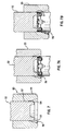
- FIG. 6 shows a cross-sectional view through metal die 40, said die being designed to make the 90° bend in expanded wall portion 18.
- Die 40 has a cavity formed therein having inwardly tapered wall 42 terminating in a right-angled portion 44.
- a lower die nest (not shown) is used to hold the cell during the precrimping step.
- Pre-crimping is effectuated by driving die 40 downwardly onto cell 20 with sufficient force so that upper casing wall 18 is folded inwardly, first by tapered wall 42 and then by right angled portion 44 as shown in FIG. 6A. This results in the pre-crimped cell shown in FIG. 3.
- Minimal radially compressive forces are applied in this operation. Rather, the force applied is primarily directed to shaping rim 19 of casing 10 and prepositioning it for the final crimping sequence. It has been discovered that the fold-over angle made during pre-crimping should not be greater than 90° from the start position since the force required to do this in a single step increases exponentially. The application of such force in a single step increases the probability of damage to the cell casing during the operation.
- FIG. 7 shows a cross-sectional view through a single die 50 designed to complete the second bending step and the radial crimping step.
- Die 50 comprises center punch 52 and sizing die 55 which are capable of independent movement.
- Center punch 52 comprises an inner, annular lip portion 53 and an outer shoulder portion 54.
- Sizing die 50 comprises a cavity defined by inwardly tapered wall 56 and cylindrical wall 57.
- a precrimped cell (such as shown in FIG. 4) is placed beneath the die.
- Punch 52 and die 55 operate in two separate motions in a synchronous fashion to provide the desired radial crimp and subsequent cell ejection from the die.
- the final crimping sequence using die 50 is as follows.
- Die 55 and punch 52 initially travel downwardly together until lip portion 53 engages rim 19 of pre-crimped cell 20. At this point center punch 52 shapes lip 19 which is folded downwardly following the contour of shoulder 54 as shown in FIG. 7A. Center punch 52 travels to a fixed stop position so that the height of the final crimped cell is accurately controlled.
- Center punch 52 remains in the position shown in FIG. 7A and firmly holds the cell during the next operation.
- Sizing die 55 continues to be driven downwardly once center punch 52 stops.
- the downward movement of tapered wall 56 causes a radial force to be applied on expanded wall portion 18 whereby the diameter is reduced as die 55 travels down.
- Tapered wall 56 causes the radial force to first be applied near the top of the cell followed by a downward application of the radial force as die 55 moves downwardly.
- this sequence of applying the radial force results in the angular profile of bend 17 as shown in FIG. 5.
- Sizing die 55 travels downwardly just beyond the point where the radial seal is made so that cylindrical wall 57 smooths wall portion 18.
- sizing die 55 Upon reaching its lowest point of travel, sizing die 55 retracts while center punch 52 remains stationary and holds the crimped cell down. This action allows the cell to resist the upward movement of sizing die 55 and "strips" cell 20 from within sizing die 55. After sizing die 55 has cleared the top of cell 20, center punch 52 is retracted and the crimped cell 20 is free from the tooling. This sequence of movements eliminates the need of removing cell 20 from die 55 by applying a force to the sealing member to dislodge the cell from the die. Any force which is applied to the sealing member after crimping can not only damage the sealing member but may also disturb the seal between the member and the casing.
- die 55 and punch 52 can be repositioned relative to each other so that punch 52 is retracted further within die 55 than shown FIG. 7.
- die 55 performs the radial crimp first.
- Punch 52 then contacts cell rim 19 and continues to a fixed stop.
- Center punch 52 remains in this position as sizing die 55 is retracted, stripping the crimped cell from the die. Once cell 20 is free from sixing die 55 center punch 52 retracts, thus completing the crimp cycle.
Landscapes
- Chemical & Material Sciences (AREA)
- Chemical Kinetics & Catalysis (AREA)
- Electrochemistry (AREA)
- General Chemical & Material Sciences (AREA)
- Sealing Battery Cases Or Jackets (AREA)
- Immobilizing And Processing Of Enzymes And Microorganisms (AREA)
- Micro-Organisms Or Cultivation Processes Thereof (AREA)
- Packaging Of Annular Or Rod-Shaped Articles, Wearing Apparel, Cassettes, Or The Like (AREA)
Claims (12)
- Procédé pour obturer hermétiquement un récipient (20), consistant à mettre en place un élément circulaire élastique (30) d'obturation dans l'extrémité ouverte d'un récipient métallique cylindrique (20) et sur un épaulement (16) tourné vers l'extérieur à proximité de l'extrémité ouverte, le dessus de l'élément d'obturation étant placé au-dessous du bord supérieur du récipient ; à plier le bord du récipient vers l'intérieur par-dessus une nervure périphérique (33) de l'élément d'obturation et, simultanément, à comprimer ladite nervure entre le bord plié du récipient et la paroi du récipient et à maintenir ledit élément vers le bas sur l'épaulement ; et à réduire le diamètre de la partie épaulée du récipient afin de le rendre égal à celui de la partie restante du récipient de façon que le diamètre de l'élément d'obturation soit réduit et que ledit élément soit maintenu en place en étant comprimé.
- Procédé selon la revendication 1, dans lequel on plie le bord du récipient vers l'intérieur en pliant d'abord ledit bord vers l'intérieur d'un angle d'environ 90° à partir de la position de départ et, dans une seconde étape de pliage, en pliant davantage ledit bord vers l'intérieur et vers le bas d'un angle supérieur à 90° à partir de ladite position de départ.
- Procédé selon la revendication 1, dans lequel on réduit le diamètre de la partie épaulée du récipient en appliquant des forces radiales dirigées vers l'intérieur, uniformément autour de ladite partie épaulée.
- Procédé selon la revendication 3, consistant à appliquer d'abord les forces radiales à proximité de l'extrémité supérieure du récipient puis à déplacer l'application des forces vers le bas jusqu'à ce que le diamètre de la partie épaulée soit réduit approximativement au même diamètre que celui de la partie restante du récipient.
- Procédé pour obturer un récipient, consistant à placer un élément circulaire élastique (30) d'obturation dans l'extrémité ouverte d'un récipient métallique cylindrique (20) et sur un épaulement (16) tourné vers l'extérieur à proximité de l'extrémité ouverte, le dessus de l'élément d'obturation étant placé au-dessous du bord supérieur du récipient ; à plier le bord du récipient vers l'intérieur par-dessus une nervure périphérique (33) de l'élément d'obturation et d'un angle d'environ 90° à partir de la position de départ, et à maintenir ledit élément d'obturation vers le bas contre l'épaulement (16) ; à réduire le diamètre de la partie épaulée du récipient pour qu'il soit égal à celui de la partie restante du récipient afin que le diamètre de l'élément d'obturation soit réduit et que ledit élément soit maintenu en place en étant comprimé ; et à plier davantage le bord du récipient vers l'intérieur et vers le bas pour que la périphérie de l'élément d'obturation soit enfermée entre le bord du récipient et sa partie épaulée réduite.
- Procédé pour obturer une pile électrochimique cylindrique ayant un récipient métallique (20) ouvert à une extrémité, consistant à placer un élément circulaire élastique d'obturation et d'isolation (30) dans l'extrémité ouverte du récipient et sur un épaulement (16), tourné vers l'extérieur, proche de l'extrémité ouverte, la surface supérieure de l'élément d'obturation étant placée au-dessous du bord supérieur du récipient ; à plier le bord du récipient vers l'intérieur par-dessus une nervure périphérique (33) de l'élément d'obturation et, simultanément, à comprimer la nervure entre le bord plié et la partie épaulée du récipient et à maintenir l'élément d'obturation vers le bas contre l'épaulement ; et à appliquer les forces radiales dirigées vers l'intérieur uniformément le long de la circonférence de la partie épaulée du récipient pour en réduire le diamètre afin que le diamètre de l'élément d'obturation soit également réduit et que ledit élément soit maintenu en place en étant comprimé.
- Procédé selon la revendication 6, dans lequel on plie vers l'intérieur ledit bord du récipient par-dessus la périphérie de l'élément d'obturation en pliant d'abord le bord vers l'intérieur d'un angle d'environ 90° à partir de la position de départ, puis en pliant vers le bas ledit rebord d'un angle de plus de 90° à partir de la position de départ.
- Procédé selon la revendication 7, consistant à appliquer axialement par impact une matrice (40) de présertissage sur ladite partie épaulée pour former ledit pli à 90° en une seule opération, ladite matrice (40) ayant une cavité destinée à recevoir ladite partie épaulée, ladite cavité ayant une paroi (42) conique vers l'intérieur aboutissant dans une partie (44) à angle droit afin que, lorsque ladite matrice est appliquée par impact sur ladite partie épaulée, ladite partie entre dans la cavité et le bord du récipient soit plié progressivement vers l'intérieur jusqu'à ce qu'un angle de 90° soit formé pendant que la partie épaulée suit le contour de la cavité.
- Procédé selon la revendication 8, consistant à plier ledit bord vers le bas d'un angle de plus de 90° à partir de la position de départ en appliquant par impact un outil à poinçon (50) sur le bord plié vers l'intérieur jusqu'à une position fixe d'arrêt, la surface d'impact dudit outil à poinçon ayant une lèvre de forme annulaire entourée d'un épaulement tourné vers le haut et vers l'extérieur afin que la lèvre annulaire engage le bord de la pile et plie ledit bord vers le bas et que ledit épaulement façonne un pli dans la partie épaulée du récipient de la pile pour former le rebord de ladite pile.
- Procédé selon la revendication 9, consistant à appliquer des forces radiales dirigées vers l'intérieur à ladite partie épaulée en faisant coulisser axialement une matrice annulaire (55) de calibrage vers le bas sur ladite partie épaulée jusqu'à un point au-delà dudit épaulement tandis que ladite pile est maintenue abaissée par ledit outil à poinçon, ladite matrice de calibrage présentant un alésage intérieur destiné à recevoir et à appliquer des forces radiales à ladite pile, ledit alésage comportant une paroi (56) conique vers l'intérieur, ayant un diamètre, à son extrémité la plus basse, assez grand pour recevoir ladite pile et un diamètre, à son extrémité supérieure, sensiblement égal au diamètre de la partie restante du récipient de la pile afin que, lorsque la matrice de calibrage descend en glissant sur ladite pile, la paroi conique applique d'abord des forces radiales à proximité du dessus de ladite pile et que l'application desdites forces radiales descende pendant que la matrice descend jusqu'à ce que le diamètre de la partie épaulée soit réduit pour être sensiblement égal au diamètre de la partie restante du récipient de la pile.
- Procédé selon la revendication 10, consistant à rétracter ladite matrice de calibrage de ladite pile tandis que ladite pile est maintenue abaissée par ledit outil à poinçon.
- Procédé selon la revendication 11, consistant à rétracter ledit outil à poinçon pour libérer la pile sertie.
Applications Claiming Priority (3)
| Application Number | Priority Date | Filing Date | Title |
|---|---|---|---|
| US580069 | 1990-09-10 | ||
| US07/580,069 US5150602A (en) | 1990-09-10 | 1990-09-10 | Crimping method for electrochemical cells |
| PCT/US1991/006241 WO1992004738A1 (fr) | 1990-09-10 | 1991-09-03 | Procede de sertissage de cellules electrochimiques |
Publications (3)
| Publication Number | Publication Date |
|---|---|
| EP0548249A1 EP0548249A1 (fr) | 1993-06-30 |
| EP0548249A4 EP0548249A4 (en) | 1993-11-03 |
| EP0548249B1 true EP0548249B1 (fr) | 1995-06-21 |
Family
ID=24319537
Family Applications (1)
| Application Number | Title | Priority Date | Filing Date |
|---|---|---|---|
| EP91917455A Expired - Lifetime EP0548249B1 (fr) | 1990-09-10 | 1991-09-03 | Procede de sertissage de cellules electrochimiques |
Country Status (12)
| Country | Link |
|---|---|
| US (1) | US5150602A (fr) |
| EP (1) | EP0548249B1 (fr) |
| JP (1) | JP2854135B2 (fr) |
| CN (1) | CN1042275C (fr) |
| AT (1) | ATE124170T1 (fr) |
| AU (1) | AU643840B2 (fr) |
| BR (1) | BR9106817A (fr) |
| CA (1) | CA2090458C (fr) |
| DE (1) | DE69110683T2 (fr) |
| MX (1) | MX174509B (fr) |
| NZ (1) | NZ239607A (fr) |
| WO (1) | WO1992004738A1 (fr) |
Families Citing this family (29)
| Publication number | Priority date | Publication date | Assignee | Title |
|---|---|---|---|---|
| HU914042D0 (en) * | 1991-12-19 | 1992-04-28 | Environmetal Batteries Systems | Cylindrical cell with improved current lead |
| US5372897A (en) * | 1992-07-24 | 1994-12-13 | Toshiba Battery Co., Ltd. | Rectangular nickel-metal hydride secondary cell |
| IL114881A (en) * | 1994-08-24 | 1998-01-04 | Duracell Inc | Electrochemical cell gasket support disc |
| US5532081A (en) * | 1994-08-24 | 1996-07-02 | Duracell Inc. | Upward deflecting support disk for electrochemical cell seal |
| US5491038A (en) * | 1994-08-24 | 1996-02-13 | Duracell Inc. | Contact ring for on-cell battery tester |
| IL114880A (en) * | 1994-08-24 | 1998-09-24 | Duracell Inc | Electrochemical cell gasket |
| JP3016065B2 (ja) * | 1995-11-10 | 2000-03-06 | 古河電池株式会社 | 円筒形ニッケル・水素二次電池の製造方法 |
| US6010802A (en) * | 1996-01-22 | 2000-01-04 | Rayovac Corporation | Current collector assembly |
| US5925478A (en) * | 1997-06-25 | 1999-07-20 | Eveready Battery Company, Inc. | V-shaped gasket for galvanic cells |
| US5932371A (en) * | 1997-06-30 | 1999-08-03 | Eveready Battery Company, Inc. | Snap-through gasket for galvanic cells |
| US5962158A (en) * | 1997-07-21 | 1999-10-05 | Duracell Inc. | End cap assembly for electrochemical cell |
| US6001504A (en) * | 1998-03-11 | 1999-12-14 | Duracell Inc. | Prismatic battery housing |
| US6081992A (en) * | 1998-07-02 | 2000-07-04 | Eveready Battery Company, Inc. | Electrochemical cell formed with big mouth open end can |
| US6042967A (en) * | 1998-07-29 | 2000-03-28 | Duracell Inc | End cap seal assembly for an electrochemical cell |
| US6126704A (en) * | 1998-08-27 | 2000-10-03 | Duracell Inc. | Method of forming a terminal pip protrusion on the casing of an alkaline cell |
| CN1336015A (zh) * | 1998-12-15 | 2002-02-13 | 杜拉塞尔公司 | 电化学电池封装 |
| US6423438B1 (en) | 2000-01-31 | 2002-07-23 | The Gillette Company | Method for sealing battery container |
| TW533620B (en) * | 2001-07-24 | 2003-05-21 | Asia Pacific Fuel Cell Tech | Metal hydride hydrogen storage canister design and its manufacture |
| US6887614B2 (en) | 2001-07-30 | 2005-05-03 | The Gillette Company | End cap assembly for an electrochemical cell |
| JP2003164043A (ja) * | 2001-11-29 | 2003-06-06 | Yazaki Corp | グロメット |
| US8393346B2 (en) * | 2004-08-12 | 2013-03-12 | Parker-Hannifin Corporation | Solenoid valve and method of assembly thereof |
| KR100912789B1 (ko) * | 2006-09-11 | 2009-08-18 | 주식회사 엘지화학 | 안전성이 향상된 원통형 이차전지 |
| KR100948001B1 (ko) * | 2006-12-11 | 2010-03-18 | 주식회사 엘지화학 | 안전성이 강화된 클림핑 형상의 리튬이온 이차전지 |
| US8236444B2 (en) * | 2007-03-27 | 2012-08-07 | Eveready Battery Company, Inc. | Electrochemical cell having low volume collector assembly |
| EP2347461B1 (fr) | 2008-11-21 | 2016-04-06 | Johnson Controls Saft Advanced Power Solutions LLC | Collecteur de courant pour une cellule électrochimique |
| KR101240717B1 (ko) | 2010-10-13 | 2013-03-11 | 삼성에스디아이 주식회사 | 이차 전지 |
| CN102569835B (zh) * | 2012-02-09 | 2014-12-10 | 四川长虹新能源科技有限公司 | 一种碱性电池制作方法及装置 |
| CN104505474A (zh) * | 2014-12-19 | 2015-04-08 | 深圳市电科电源股份有限公司 | 提高圆柱电池气密的方法及圆柱电池 |
| CN114759321B (zh) * | 2022-05-24 | 2024-03-08 | 厦门海辰储能科技股份有限公司 | 电池以及密封方法 |
Family Cites Families (13)
| Publication number | Priority date | Publication date | Assignee | Title |
|---|---|---|---|---|
| SU197709A1 (fr) * | 1965-02-20 | 1967-08-18 | ||
| US3859141A (en) * | 1971-09-01 | 1975-01-07 | Gould Inc | Dry battery seal and terminal connection |
| US4020241A (en) * | 1976-03-29 | 1977-04-26 | Union Carbide Corporation | Galvanic cell having a resealable vent closure |
| SU574790A1 (ru) * | 1976-05-17 | 1977-09-30 | Предприятие П/Я В-2763 | Способ герметизации химического источника тока |
| US4052537A (en) * | 1976-10-01 | 1977-10-04 | P. R. Mallory & Co. Inc. | Electrical device |
| US4532705A (en) * | 1980-09-26 | 1985-08-06 | Union Carbide Corporation | Method of making an electrochemical cell having a resealable vent closure |
| JPS58186152A (ja) * | 1982-04-22 | 1983-10-31 | Shin Kobe Electric Mach Co Ltd | 円筒形電池の封口方法 |
| US4442184A (en) * | 1983-03-31 | 1984-04-10 | Union Carbide Corporation | Dry path gas venting seal |
| JPS6129062A (ja) * | 1984-07-19 | 1986-02-08 | Matsushita Electric Ind Co Ltd | 電池の封口かしめ金型 |
| JPS61233963A (ja) * | 1985-04-09 | 1986-10-18 | Sanyo Electric Co Ltd | 円筒形電池の製造方法 |
| US4656736A (en) * | 1986-01-08 | 1987-04-14 | Vsesojuny Nauchno-Issledovatelsky Proektno-Konstruktorsky I Tekhnologichesky Akkumulyatorny Institut | Apparatus for sealing a cylindrical storage cell |
| US4822377A (en) * | 1988-02-18 | 1989-04-18 | Energy Conversion Devices, Inc. | Method for sealing an electrochemical cell employing an improved reinforced cover assembly |
| JPH01253152A (ja) * | 1988-03-31 | 1989-10-09 | Shin Kobe Electric Mach Co Ltd | 円筒密閉形電池の封口装置 |
-
1990
- 1990-09-10 US US07/580,069 patent/US5150602A/en not_active Expired - Lifetime
-
1991
- 1991-08-30 NZ NZ239607A patent/NZ239607A/en unknown
- 1991-09-03 EP EP91917455A patent/EP0548249B1/fr not_active Expired - Lifetime
- 1991-09-03 AU AU86285/91A patent/AU643840B2/en not_active Ceased
- 1991-09-03 BR BR919106817A patent/BR9106817A/pt not_active IP Right Cessation
- 1991-09-03 AT AT91917455T patent/ATE124170T1/de not_active IP Right Cessation
- 1991-09-03 JP JP3516043A patent/JP2854135B2/ja not_active Expired - Fee Related
- 1991-09-03 DE DE69110683T patent/DE69110683T2/de not_active Expired - Lifetime
- 1991-09-03 CA CA002090458A patent/CA2090458C/fr not_active Expired - Fee Related
- 1991-09-03 WO PCT/US1991/006241 patent/WO1992004738A1/fr not_active Ceased
- 1991-09-09 CN CN91109575A patent/CN1042275C/zh not_active Expired - Lifetime
- 1991-09-10 MX MX9101002A patent/MX174509B/es not_active IP Right Cessation
Also Published As
| Publication number | Publication date |
|---|---|
| US5150602A (en) | 1992-09-29 |
| CN1042275C (zh) | 1999-02-24 |
| JPH06502958A (ja) | 1994-03-31 |
| CA2090458C (fr) | 2000-01-04 |
| DE69110683T2 (de) | 1996-01-18 |
| JP2854135B2 (ja) | 1999-02-03 |
| WO1992004738A1 (fr) | 1992-03-19 |
| CN1061303A (zh) | 1992-05-20 |
| MX174509B (es) | 1994-05-20 |
| AU8628591A (en) | 1992-03-30 |
| CA2090458A1 (fr) | 1992-03-11 |
| DE69110683D1 (de) | 1995-07-27 |
| EP0548249A4 (en) | 1993-11-03 |
| BR9106817A (pt) | 1993-06-15 |
| AU643840B2 (en) | 1993-11-25 |
| ATE124170T1 (de) | 1995-07-15 |
| NZ239607A (en) | 1994-03-25 |
| EP0548249A1 (fr) | 1993-06-30 |
Similar Documents
| Publication | Publication Date | Title |
|---|---|---|
| AU643840B2 (en) | Crimping method for electrochemical cells | |
| US5685189A (en) | Method and apparatus for producing container body end countersink | |
| US4991735A (en) | Pressure resistant end shell for a container and method and apparatus for forming the same | |
| US3868919A (en) | Method and apparatus for forming easy opening container walls | |
| CA2339648C (fr) | Procede et dispositif de formation d'une extremite de boite metallique presentant un bourrelet sans apparition de cretes | |
| NO174284B (no) | Boxsende samt fremgangsmaate og anordning for forming av et avstivet lokk'for en slik boksende | |
| JP4064813B2 (ja) | 被覆組立体を有するバッテリー構造及びその組立方法 | |
| EP0398529A1 (fr) | Assemblage d'étampe et méthode de manufacture d'un couvercle métallique | |
| US6290447B1 (en) | Single station blanked, formed and curled can end with outward formed curl | |
| US4372720A (en) | Forming of end closures | |
| US4958757A (en) | Ferrule for sealing with a container | |
| EP0237161A2 (fr) | Procédé et appareil pour le bombage des fonds de boîtes | |
| JPS58184024A (ja) | 絞り型 | |
| US4240197A (en) | Method for sealing a primary cell | |
| EP0064825A1 (fr) | La fixation des pièces en matières plastiques dans des ouvertures des feuilles métalliques | |
| US4611481A (en) | Metal container end die | |
| US5950482A (en) | Method for shaping tubular member | |
| WO2001087515A1 (fr) | Fabrication a vitesse elevee d'enveloppes de contenants de boissons | |
| JP2025040727A (ja) | 板材の成形方法 | |
| KR20260073309A (ko) | 원통형 이차전지 캔 | |
| MXPA97000556A (en) | Method and apparatus to produce a delextreme hazelness of the body of a recipie | |
| JPH04349340A (ja) | 円筒形電池の製造方法 | |
| PL108520B1 (en) | Device for air-tight sealing cells,specially of cylindrical form ones | |
| JPH06260153A (ja) | 角形密閉電池の製造方法 |
Legal Events
| Date | Code | Title | Description |
|---|---|---|---|
| PUAI | Public reference made under article 153(3) epc to a published international application that has entered the european phase |
Free format text: ORIGINAL CODE: 0009012 |
|
| 17P | Request for examination filed |
Effective date: 19930309 |
|
| AK | Designated contracting states |
Kind code of ref document: A1 Designated state(s): AT BE CH DE DK ES FR GB GR IT LI LU NL SE |
|
| A4 | Supplementary search report drawn up and despatched |
Effective date: 19930916 |
|
| AK | Designated contracting states |
Kind code of ref document: A4 Designated state(s): AT BE CH DE DK ES FR GB GR IT LI LU NL SE |
|
| 17Q | First examination report despatched |
Effective date: 19940329 |
|
| GRAA | (expected) grant |
Free format text: ORIGINAL CODE: 0009210 |
|
| AK | Designated contracting states |
Kind code of ref document: B1 Designated state(s): AT BE CH DE DK ES FR GB GR IT LI LU NL SE |
|
| PG25 | Lapsed in a contracting state [announced via postgrant information from national office to epo] |
Ref country code: NL Free format text: LAPSE BECAUSE OF NON-PAYMENT OF DUE FEES Effective date: 19950621 Ref country code: ES Free format text: THE PATENT HAS BEEN ANNULLED BY A DECISION OF A NATIONAL AUTHORITY Effective date: 19950621 Ref country code: CH Effective date: 19950621 Ref country code: GR Free format text: LAPSE BECAUSE OF FAILURE TO SUBMIT A TRANSLATION OF THE DESCRIPTION OR TO PAY THE FEE WITHIN THE PRESCRIBED TIME-LIMIT Effective date: 19950621 Ref country code: DK Effective date: 19950621 Ref country code: LI Effective date: 19950621 Ref country code: AT Effective date: 19950621 |
|
| REF | Corresponds to: |
Ref document number: 124170 Country of ref document: AT Date of ref document: 19950715 Kind code of ref document: T |
|
| REF | Corresponds to: |
Ref document number: 69110683 Country of ref document: DE Date of ref document: 19950727 |
|
| ITF | It: translation for a ep patent filed | ||
| PG25 | Lapsed in a contracting state [announced via postgrant information from national office to epo] |
Ref country code: SE Effective date: 19950921 |
|
| REG | Reference to a national code |
Ref country code: CH Ref legal event code: PL |
|
| PG25 | Lapsed in a contracting state [announced via postgrant information from national office to epo] |
Ref country code: LU Free format text: LAPSE BECAUSE OF NON-PAYMENT OF DUE FEES Effective date: 19950930 |
|
| ET | Fr: translation filed | ||
| NLV1 | Nl: lapsed or annulled due to failure to fulfill the requirements of art. 29p and 29m of the patents act | ||
| PLBE | No opposition filed within time limit |
Free format text: ORIGINAL CODE: 0009261 |
|
| STAA | Information on the status of an ep patent application or granted ep patent |
Free format text: STATUS: NO OPPOSITION FILED WITHIN TIME LIMIT |
|
| 26N | No opposition filed | ||
| REG | Reference to a national code |
Ref country code: GB Ref legal event code: IF02 |
|
| PGFP | Annual fee paid to national office [announced via postgrant information from national office to epo] |
Ref country code: FR Payment date: 20020819 Year of fee payment: 12 |
|
| PG25 | Lapsed in a contracting state [announced via postgrant information from national office to epo] |
Ref country code: FR Free format text: LAPSE BECAUSE OF NON-PAYMENT OF DUE FEES Effective date: 20040528 |
|
| REG | Reference to a national code |
Ref country code: FR Ref legal event code: ST |
|
| PG25 | Lapsed in a contracting state [announced via postgrant information from national office to epo] |
Ref country code: IT Free format text: LAPSE BECAUSE OF NON-PAYMENT OF DUE FEES;WARNING: LAPSES OF ITALIAN PATENTS WITH EFFECTIVE DATE BEFORE 2007 MAY HAVE OCCURRED AT ANY TIME BEFORE 2007. THE CORRECT EFFECTIVE DATE MAY BE DIFFERENT FROM THE ONE RECORDED. Effective date: 20050903 |
|
| BECA | Be: change of holder's address |
Owner name: THE *GILLETTE CYPRUDENTIAL TOWER BUILDING, US-BOST Effective date: 20080228 |
|
| BECH | Be: change of holder |
Owner name: THE *GILLETTE CY Effective date: 20080228 |
|
| REG | Reference to a national code |
Ref country code: GB Ref legal event code: 732E |
|
| PGFP | Annual fee paid to national office [announced via postgrant information from national office to epo] |
Ref country code: GB Payment date: 20090807 Year of fee payment: 19 |
|
| PGFP | Annual fee paid to national office [announced via postgrant information from national office to epo] |
Ref country code: DE Payment date: 20090930 Year of fee payment: 19 |
|
| PGFP | Annual fee paid to national office [announced via postgrant information from national office to epo] |
Ref country code: BE Payment date: 20101012 Year of fee payment: 20 |
|
| GBPC | Gb: european patent ceased through non-payment of renewal fee |
Effective date: 20100903 |
|
| REG | Reference to a national code |
Ref country code: DE Ref legal event code: R119 Ref document number: 69110683 Country of ref document: DE Effective date: 20110401 |
|
| PG25 | Lapsed in a contracting state [announced via postgrant information from national office to epo] |
Ref country code: DE Free format text: LAPSE BECAUSE OF NON-PAYMENT OF DUE FEES Effective date: 20110401 |
|
| PG25 | Lapsed in a contracting state [announced via postgrant information from national office to epo] |
Ref country code: GB Free format text: LAPSE BECAUSE OF NON-PAYMENT OF DUE FEES Effective date: 20100903 |
|
| BE20 | Be: patent expired |
Owner name: THE *GILLETTE CY Effective date: 20110903 |