EP0548283B1 - Originalitätsverschluss mit irreversiblem farbänderungssystem - Google Patents
Originalitätsverschluss mit irreversiblem farbänderungssystem Download PDFInfo
- Publication number
- EP0548283B1 EP0548283B1 EP91919000A EP91919000A EP0548283B1 EP 0548283 B1 EP0548283 B1 EP 0548283B1 EP 91919000 A EP91919000 A EP 91919000A EP 91919000 A EP91919000 A EP 91919000A EP 0548283 B1 EP0548283 B1 EP 0548283B1
- Authority
- EP
- European Patent Office
- Prior art keywords
- button
- closure
- colored
- layer
- layers
- Prior art date
- Legal status (The legal status is an assumption and is not a legal conclusion. Google has not performed a legal analysis and makes no representation as to the accuracy of the status listed.)
- Expired - Lifetime
Links
- 230000002427 irreversible effect Effects 0.000 title 1
- 238000000576 coating method Methods 0.000 claims abstract description 39
- 239000011248 coating agent Substances 0.000 claims abstract description 36
- 239000011247 coating layer Substances 0.000 claims abstract description 22
- 239000003086 colorant Substances 0.000 claims abstract description 9
- 230000013011 mating Effects 0.000 claims abstract description 3
- 239000010410 layer Substances 0.000 claims description 92
- 230000000694 effects Effects 0.000 claims description 11
- 239000000463 material Substances 0.000 claims description 6
- 238000006116 polymerization reaction Methods 0.000 claims description 3
- 238000000034 method Methods 0.000 claims 6
- 238000010276 construction Methods 0.000 description 2
- 238000000926 separation method Methods 0.000 description 2
- 230000000717 retained effect Effects 0.000 description 1
Images


Classifications
-
- B—PERFORMING OPERATIONS; TRANSPORTING
- B65—CONVEYING; PACKING; STORING; HANDLING THIN OR FILAMENTARY MATERIAL
- B65D—CONTAINERS FOR STORAGE OR TRANSPORT OF ARTICLES OR MATERIALS, e.g. BAGS, BARRELS, BOTTLES, BOXES, CANS, CARTONS, CRATES, DRUMS, JARS, TANKS, HOPPERS, FORWARDING CONTAINERS; ACCESSORIES, CLOSURES, OR FITTINGS THEREFOR; PACKAGING ELEMENTS; PACKAGES
- B65D55/00—Accessories for container closures not otherwise provided for
- B65D55/02—Locking devices; Means for discouraging or indicating unauthorised opening or removal of closure
- B65D55/026—Locking devices; Means for discouraging or indicating unauthorised opening or removal of closure initial opening or unauthorised access being indicated by a visual change using indicators other than tearable means, e.g. change of colour, pattern or opacity
-
- B—PERFORMING OPERATIONS; TRANSPORTING
- B65—CONVEYING; PACKING; STORING; HANDLING THIN OR FILAMENTARY MATERIAL
- B65D—CONTAINERS FOR STORAGE OR TRANSPORT OF ARTICLES OR MATERIALS, e.g. BAGS, BARRELS, BOTTLES, BOXES, CANS, CARTONS, CRATES, DRUMS, JARS, TANKS, HOPPERS, FORWARDING CONTAINERS; ACCESSORIES, CLOSURES, OR FITTINGS THEREFOR; PACKAGING ELEMENTS; PACKAGES
- B65D79/00—Kinds or details of packages, not otherwise provided for
- B65D79/005—Packages having deformable parts for indicating or neutralizing internal pressure-variations by other means than venting
- B65D79/0087—Packages having deformable parts for indicating or neutralizing internal pressure-variations by other means than venting the deformable part being located in a closure, e.g. in caps or lids
-
- B—PERFORMING OPERATIONS; TRANSPORTING
- B65—CONVEYING; PACKING; STORING; HANDLING THIN OR FILAMENTARY MATERIAL
- B65D—CONTAINERS FOR STORAGE OR TRANSPORT OF ARTICLES OR MATERIALS, e.g. BAGS, BARRELS, BOTTLES, BOXES, CANS, CARTONS, CRATES, DRUMS, JARS, TANKS, HOPPERS, FORWARDING CONTAINERS; ACCESSORIES, CLOSURES, OR FITTINGS THEREFOR; PACKAGING ELEMENTS; PACKAGES
- B65D2401/00—Tamper-indicating means
- B65D2401/55—Tamper-indicating means based on a change or a contrast in colour
-
- Y—GENERAL TAGGING OF NEW TECHNOLOGICAL DEVELOPMENTS; GENERAL TAGGING OF CROSS-SECTIONAL TECHNOLOGIES SPANNING OVER SEVERAL SECTIONS OF THE IPC; TECHNICAL SUBJECTS COVERED BY FORMER USPC CROSS-REFERENCE ART COLLECTIONS [XRACs] AND DIGESTS
- Y10—TECHNICAL SUBJECTS COVERED BY FORMER USPC
- Y10S—TECHNICAL SUBJECTS COVERED BY FORMER USPC CROSS-REFERENCE ART COLLECTIONS [XRACs] AND DIGESTS
- Y10S428/00—Stock material or miscellaneous articles
- Y10S428/916—Fraud or tamper detecting
-
- Y—GENERAL TAGGING OF NEW TECHNOLOGICAL DEVELOPMENTS; GENERAL TAGGING OF CROSS-SECTIONAL TECHNOLOGIES SPANNING OVER SEVERAL SECTIONS OF THE IPC; TECHNICAL SUBJECTS COVERED BY FORMER USPC CROSS-REFERENCE ART COLLECTIONS [XRACs] AND DIGESTS
- Y10—TECHNICAL SUBJECTS COVERED BY FORMER USPC
- Y10T—TECHNICAL SUBJECTS COVERED BY FORMER US CLASSIFICATION
- Y10T428/00—Stock material or miscellaneous articles
- Y10T428/24—Structurally defined web or sheet [e.g., overall dimension, etc.]
- Y10T428/24802—Discontinuous or differential coating, impregnation or bond [e.g., artwork, printing, retouched photograph, etc.]
- Y10T428/24917—Discontinuous or differential coating, impregnation or bond [e.g., artwork, printing, retouched photograph, etc.] including metal layer
Definitions
- This invention relates to closures having tamper indicating means, and more specifically to a closure of the type having a button which is displaced when the closure is applied to a container so as to indicate the condition of closing (see e.g. US-A-3.736.899).
- closures with end panels having buttons formed therein so as to indicate the condition of closure.
- Such closures include those in which the button is actuated by a vacuum condition within an associated container and those wherein the buttons are mechanically actuated when the closure is applied to a container under non-vacuum conditions.
- buttons of closures indicating means which will provide either a color indication or a display showing that the closure has been applied and then removed.
- the closure condition indicating button is provided with an enhancement coating system which includes two differently colored layers with the outer layer being preferably transparent so as to provide a color which is a combination of the colors of the two layers as long as the two layers are bonded together.
- the color appearance of the button is only that of the outer layer.
- This invention most particularly relates to the shrinking of the outer layer so as to effect separation of the two layers when the button returns to its starting position after the closure has been removed from an associated container.
- the outer layer is formed of a partially polymerized material, which material is further polymerized after the closure has been applied to a container and the button displaced from its manufactured position so as to effect the shrinkage of the outer layer.
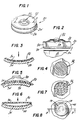
- Fig. 1 is a top perspective view of a conventional type of closure having a mechanically actuated button.
- Fig. 2 is a fragmentary large vertical sectional view taken generally along the line 2-2 of Fig. 1 and shows more specifically the details of the button and the tamper indicating enhancement thereof.
- Fig. 3 is an enlargement of the encircled portion of Fig. 2 and shows specifically the details of the tamper indicating enhancement with the button in its down as manufactured position.
- Fig. 4 is a plan view of the button displaying a certain color.
- Fig. 5 is an enlarged fragmentary sectional view similar to Fig. 3 showing the button in its mechanically displaced position after the closure has been applied to a container with the outer layer being treated to effect shrinkage thereof.
- Fig. 6 is an enlarged fragmentary sectional view through the button after the closure has been removed from an associated container and the button mechanically returned to its original position and with the two layers having separated from one another.
- Fig. 7 is a plan view of the button in its condition of Fig. 6 wherein the appearance of the button is of another color.
- Fig. 8 is a plan view of a slightly modified button wherein the inner layer is embossed to provide a plurality of concentric grooves.
- Fig. 9 is an enlarged fragmentary vertical sectional view taken through the button of Fig. 8 and shows the specific embossed configuration of the inner layer with the outer layer having flowed into the grooves formed in the outer surface of the inner layer.
- Fig. 10 is an enlarged fragmentary sectional view through the button of Fig. 8 with the button deflected due to the application of the closure to a container and the outer layer being treated to effect the shrinkage thereof whereby separation of the two layers will be effected at least when the button snaps back to its original position.
- Fig. 11 is another sectional view showing the button having returned to its original position and the shrinkage of the outer layer preventing an internesting of the opposed surfaces of the two layers.
- Fig. 12 is a top perspective view of another closure which incorporates a vacuum actuated button.
- Fig. 13 is an enlarged fragmentary vertical sectional view taken through the closure of Fig. 12 and shows the button with the enhancement coating system thereon.
- Fig. 14 is an enlarged fragmentary vertical sectional view of the encircled portion of the button of Fig. 13 and shows more specifically the details of the enhancement coating system.
- Fig. 15 is a sectional view similar to Fig. 14 and shows the button in a downwardly drawn position when the closure is applied to a vacuum packed container, the view also shows the treatment of the outer layer to effect shrinkage thereof.
- Fig. 16 is another vertical sectional view similar to Fig. 14 and shows the button as it appears when it returns to its original position following the removal of the closure from the vacuum packed container with the two layers being spaced apart.
- a first embodiment of the invention which includes a closure generally identified by the numeral 20.
- the closure 20 is of a basic known construction and includes an end panel 22 carried by a cylindrical skirt 24 and the skirt 24 terminating in a curl 26 which will be provided with means for interlocking engagement with lugs of a conventional container.
- the central part of the end panel 22 is provided with a mechanically actuated button 28 which is best illustrated in Fig. 2 and which button has an as formed downwardly deflected configuration.
- the button 28 When the closure 20 is applied to a container, such as the container 30, the button 28 will be deflected to an upwardly directed position as is shown in Fig. 5. Then when the closure 20 is removed from the container 30, the button 28, due to internal forces, will snap back down to its original position as shown in Fig. 6.
- This invention particularly relates to a button enhancement coating system which is applied to the button 28 and is generally identified by the numeral 32.
- the button enhancement coating system 32 is particularly constructed to specifically designate that the closure 20 has been removed from the container 30 even if the closure 20 is again placed on the container 30 in a sealed closed position and thus forms tamper indicating means for the closure 20.
- the button enhancement coating system 32 includes a first colored layer 34 in the form of a coating applied to the button 28 for movement with the button 28.
- the button enhancement coating system 32 also includes a second layer 36 which overlies the coating layer 34 and is initially bonded thereto, the layer 36 being in the form of a partially polymerized transparent coating which is of a second and different color from the layer 34.
- a typical example of the colors of the layers 34 and 36 would be for the layer 34 to be blue and the layer 36 to be yellow.
- the coating system would have a green appearance.
- the two layers 34, 36 are separated, as shown in Figs. 6 and 7, only the color of the yellow layer 36 would be seen.
- the layers 34 and 36 will become permanently separated and that the color of the coated button 28 will remain that of the layer 36 even if the closure is reapplied to the container.
- the outer layer 36 is treated so as to effect a shrinkage of the same.
- the bond between the layers 34, 36 is just enough to keep the two layers from separating at this time.
- the button 28 snaps down due to the retained energy therein, to the position of Fig. 6, since the layer 36 is of a lesser extent than the layer 34, it will become separated from the layer 34 as is shown in Fig. 6.
- the color of the button 38 goes from green to yellow when the colors of the layers 34 and 36 are blue and yellow, respectively.
- a closure generally identified by the numeral 40.
- the closure 40 is of a construction somewhat similar to that of the closure 20 and includes an end panel 42 carried by a generally cylindrical skirt 44 which terminates in a lower curl 46 having means (not shown) for interlock securing engagement with a container such as the container 50 of Fig. 13.
- the end panel 42 is provided with a container closed position indicating button 48 as shown in Fig. 13 in a manner similar to the button 28.
- the button 48 is directed upwardly and the closure 40 is particularly constructed to form part of a vacuum packed package with the vacuum within the container 50 drawing the button 48 downwardly when the vacuum is effected in such package.
- the button 48 is provided with a button enhancement coating system generally identified by the numeral 52 with the coating system being substantially identical to that of the coating system 32.
- the button enhancement coating system 52 includes a first colored coating 54 which is applied to the top surface of the button 48 for movement therewith.
- a second colored coating 56 is applied over the coating 54 and is bonded thereto.
- the coatings 54 and 56 may be identical to the coatings 34 and 36, respectively with the coating 54 being a blue coating and the coating 56 being a partially polymerized transparent yellow coating or other color combinations may be utilized as discussed above.
- Fig. 15 it will be seen that when the closure 40 is applied to the container 50 and a vacuum is drawn within the container 50, the button 48 is displaced to a downwardly projecting position.
- the coating 56 is provided with a treatment generally designated by the numeral 58 so as to effect a shrinkage of the layer 56.
- This treatment 58 will be of the same type as the previously described treatment 38 and in the case where the layer is partially polymerized coating, will be in the form of a further polymerization of the layer 56.
- the bond between the layers 54, 56 is just enough to keep the two layers from separating.
- Figs. 8-11 After the closure of Figs. 8-11 has been applied to a container and a vacuum drawn within the container, the button 48 is drawn downwardly as shown in Fig. 10. At this time the treatment 58 is applied to the coating 66 so as to effect shrinkage thereof as described with respect to Fig. 10. At this time there still remains a very slight bond between the layers 64, 66.
- buttons enhancement coating system 72 utilizing the embossed coating layer 64 has been illustrated only with respect to the closure 40, a similar system may be utilized in conjunction with the closure 20.
Landscapes
- Engineering & Computer Science (AREA)
- Mechanical Engineering (AREA)
- Closures For Containers (AREA)
- Non-Silver Salt Photosensitive Materials And Non-Silver Salt Photography (AREA)
- Details Of Rigid Or Semi-Rigid Containers (AREA)
- Diaphragms For Electromechanical Transducers (AREA)
- Table Devices Or Equipment (AREA)
- Saccharide Compounds (AREA)
- Steroid Compounds (AREA)
- Materials For Medical Uses (AREA)
- Fertilizers (AREA)
- Two-Way Televisions, Distribution Of Moving Picture Or The Like (AREA)
- Bag Frames (AREA)
- Cartons (AREA)
- Packages (AREA)
Claims (19)
- Verschluß mit einer Endplatte, die einen auslenkbaren Knopf (28) aufweist, der den Zustand der Packung anzeigt, und mit einem eine Manipulation anzeigenden Mittel, das durch den Knopf getragen wird, um permanent anzuzeigen, daß der Verschluß auf einen Behälter aufgebracht und dann entfernt wurde, dadurch gekennzeichnet, daß das eine Manipulation anzeigende Mittel eine erste gefärbte Überzugsschicht (34), die mit dem Äußeren des Knopfs verbunden ist, und eine zweite gefärbte lichtdurchlässige Überzugsschicht (36) umfaßt, die lösbar mit der Außenfläche der ersten gefärbten Überzugsschicht verbunden ist, wobei die zweite gefärbte Schicht den Lichtdurchtritt zum Zwecke des Betrachtens der Farben der Schichten ermöglicht, wobei sich die Farben der Schichten, wenn man sie durch die zweite Schicht hindurch betrachtet, überlagern, um eine Farbe anzuzeigen, wenn die gefärbten Überzugsschichten miteinander verbunden sind, und nur die Farbe der zweiten gefärbten Überzugsschicht angezeigt wird, wenn die gefärbten Überzugsschichten voneinander getrennt werden.
- Verschluß nach Anspruch 1, worin der Verschluß auf einen Behälter aufgebracht wurde, der Knopf ausgelenkt wurde, um einen richtig geschlossenen Zustand anzuzeigen und die zweite gefärbte Schicht behandelt wurde, um ihr Schrumpfen zu bewirken.
- Verschluß nach Anspruch 2, worin der Verschluß aufgebracht und die zweite Farbschicht behandelt wurde, wobei die Bindung zwischen den gefärbten Schichten gerade ausreicht, um die Trennung der gefärbten Schicht voneinander zu verhindern.
- Verschluß nach Anspruch 2, worin der Verschluß vom Behälter entfernt wurde und der Knopf wieder in seine ursprüngliche Form zurückgekehrt ist, die zwei gefärbten Schichten sich voneinander lösten und die Farbe des eine Manipulation anzeigenden Mittels im wesentlichen jene der zweiten gefärbten Schicht ist, was das Aufbringen und das anschließende Entfernen des Verschlusses anzeigt.
- Verschluß nach Anspruch 1, worin die zweite gefärbte Schicht ein teilweise polymerisiertes Material ist.
- Verschluß nach Anspruch 2, worin die zweite gefärbte Schicht ein teilweise polymerisiertes Material ist und die Behandlung zur Herbeiführung des Schrumpfens der zweiten gefärbten Schicht eine weitere Polymerisation des Materials der zweiten gefärbten Schicht ist.
- Verschluß nach Anspruch 1, worin der Knopf ein mechanisch betätigter Knopf mit einer im nicht aufgebrachten Zustand unteren Position ist.
- Verschluß nach Anspruch 2, worin der Knopf ein mechanisch betätigter Knopf mit einer im nicht aufgebrachten Zustand unteren Position und einer im aufgebrachten Zustand oberen Position ist.
- Verschluß nach Anspruch 1, worin der Knopf ein vakuumbetätigter Knopf mit einer im nicht aufgebrachten Zustand oberen Position ist.
- Verschluß nach Anspruch 2, worin der Knopf ein vakuumbetätigter Knopf mit einer im nicht aufgebrachten Zustand oberen Position und einer im aufgebrachten Zustand unteren Position ist.
- Verschluß nach Anspruch 1, worin die Außenfläche der ersten gefärbten Schicht geprägt ist, um beabstandete hervorstehende Rippen (68) aufzuweisen, und die zweite gefärbte Schicht eine in die Vertiefungen zwischen den Rippen geflossene Innenfläche aufweist.
- Verschluß nach Anspruch 11, worin die Rippen konzentrisch angeordnet sind.
- Verschluß nach Anspruch 11, worin die Rippen konzentrisch angeordnet sind und unterschiedliche Breiten aufweisen.
- Verschluß nach Anspruch 11, worin die Rippen unterschiedliche Breiten aufweisen.
- Verfahren zum Ausbilden eines eine Manipulation anzeigenden Verschlusses mit einem Mittel zum Anzeigen, daß der Verschluß auf einen Behälter aufgebracht und dann gelöst wurde, wobei das Verfahren die folgenden Schritte umfaßt: das Vorsehen eines Verschlusses mit einer Endplatte, die einen auslenkbaren Knopf (28) aufweist, der einen Zustand der Packung anzeigt, und mit einem eine Manipulation anzeigenden Mittel, das durch den Knopf getragen wird, um dauernd anzuzeigen, daß der Verschluß auf einen Behälter aufgebracht und entfernt wurde, dadurch gekennzeichnet, daß das eine Manipulation anzeigende Mittel eine erste gefärbte Überzugsschicht (34), die mit einer Außenfläche des Knopfs verbunden ist, und eine zweite gefärbte lichtdurchlässige Überzugsschicht (36) umfaßt, die lösbar mit einer Außenfläche der ersten gefärbten Schicht verbunden ist, wobei sich die Farben der Schichten, wenn man sie durch die zweite Schicht betrachtet, überlagern, um eine Farbe anzuzeigen, wenn die gefärbten Schichten miteinander verbunden sind, und nur die Farbe der zweiten gefärbten Schicht angezeigt wird, wenn die gefärbten Schichten voneinander getrennt werden, das Aufbringen des Verschlusses auf einen Behälter und das Auslenken des Knopfs, sowie das Behandeln der zweiten gefärbten Schicht, um deren Schrumpfen zu bewirken, wodurch bei der Entfernung des Verschlusses vom Behälter und dem Auslenken des Knopfs in seine ursprüngliche Position die gefärbten Schichten voneinander getrennt werden und das eine Manipulation anzeigende Mittel seine Farbe dauerhaft verändert.
- Verfahren nach Anspruch 15, worin der Verschluß mit einem mechanisch betätigten Knopf ausgebildet wird.
- Verfahren nach Anspruch 15, worin der Verschluß mit einem vakuumbetätigten Knopf ausgebildet wird.
- Verfahren nach Anspruch 15, worin die zweite gefärbte Schicht als teilweise polymerisiertes Material ausgebildet ist und die Behandlung aus einer weiteren Polymerisation der zweiten gefärbten Schicht besteht.
- Verfahren nach Anspruch 15, worin die gefärbten Schichten mit zusammenpassenden gerippten Oberflächen (68) ausgebildet sind.
Applications Claiming Priority (3)
| Application Number | Priority Date | Filing Date | Title |
|---|---|---|---|
| US58517990A | 1990-09-20 | 1990-09-20 | |
| US585179 | 1990-09-20 | ||
| PCT/US1991/006807 WO1992005083A1 (en) | 1990-09-20 | 1991-09-19 | Button enhancement coating system |
Publications (3)
| Publication Number | Publication Date |
|---|---|
| EP0548283A1 EP0548283A1 (de) | 1993-06-30 |
| EP0548283A4 EP0548283A4 (en) | 1993-10-13 |
| EP0548283B1 true EP0548283B1 (de) | 1995-09-20 |
Family
ID=24340343
Family Applications (1)
| Application Number | Title | Priority Date | Filing Date |
|---|---|---|---|
| EP91919000A Expired - Lifetime EP0548283B1 (de) | 1990-09-20 | 1991-09-19 | Originalitätsverschluss mit irreversiblem farbänderungssystem |
Country Status (12)
| Country | Link |
|---|---|
| US (1) | US5566846A (de) |
| EP (1) | EP0548283B1 (de) |
| JP (1) | JP3035349B2 (de) |
| KR (1) | KR100196580B1 (de) |
| AT (1) | ATE128093T1 (de) |
| AU (1) | AU665519B2 (de) |
| BR (1) | BR9106872A (de) |
| CA (1) | CA2092090C (de) |
| DE (1) | DE69113275T2 (de) |
| ES (1) | ES2080343T3 (de) |
| HU (1) | HU218070B (de) |
| WO (1) | WO1992005083A1 (de) |
Cited By (2)
| Publication number | Priority date | Publication date | Assignee | Title |
|---|---|---|---|---|
| US7682696B2 (en) | 2004-09-13 | 2010-03-23 | Sabic Innovative Plastics Ip B.V. | Medical article and method of making and using the same |
| US11542080B2 (en) | 2013-05-07 | 2023-01-03 | BBB Holding Company | Track and trace packaging and systems |
Families Citing this family (9)
| Publication number | Priority date | Publication date | Assignee | Title |
|---|---|---|---|---|
| US5474194A (en) * | 1990-07-09 | 1995-12-12 | Continental White Cap, Inc. | Closure with irreversible color change system |
| US5413234A (en) * | 1992-02-12 | 1995-05-09 | Continental White Cap, Inc. | Tamper evident closure |
| AU669683B2 (en) * | 1992-02-12 | 1996-06-20 | Continental White Cap, Inc. | Tamper evident closure |
| DE19728778A1 (de) * | 1997-07-05 | 1999-01-07 | Leguin Hermann | Verschluß für einen Behälter |
| US6938768B2 (en) * | 1999-03-26 | 2005-09-06 | S.C. Johnson Home Storage, Inc. | Reusable lid with date indicating device |
| US7837048B2 (en) * | 2006-02-06 | 2010-11-23 | Ronald Lusker | Multi-colored container |
| US20110303572A1 (en) * | 2010-06-15 | 2011-12-15 | Mohammad Ashraf Rajpoot | Bottle, can or cup identifier dimples |
| EP3732115A1 (de) * | 2017-12-29 | 2020-11-04 | Avery Dennison Retail Information Services, LLC | Feststellung der dichtigkeit von produkten mittels rfid |
| US11865472B2 (en) * | 2022-03-23 | 2024-01-09 | Fat Brain Toy Co., Llc | Push and pull toy |
Family Cites Families (13)
| Publication number | Priority date | Publication date | Assignee | Title |
|---|---|---|---|---|
| DK123138B (da) * | 1970-11-10 | 1972-05-23 | A M Hirschsprung & Sonner As | Fremgangsmåde til bredning af tobaksblade og apparat til bredning af tobaksblade ved denne fremgangsmåde. |
| US3736899A (en) * | 1971-10-28 | 1973-06-05 | Minnesota Mining & Mfg | Pressure change indicator |
| US3987668A (en) * | 1975-11-17 | 1976-10-26 | Popenoe Charles H | Light reflective opti-mechanical displacement microindicator |
| US4285105A (en) * | 1978-09-29 | 1981-08-25 | Union Carbide Corporation | Colored interlocking closure strips |
| US4479585A (en) * | 1982-07-19 | 1984-10-30 | Jeffrey Sandhaus | Tamper resistant safety closure and closure-container combination |
| US4489841A (en) * | 1983-02-18 | 1984-12-25 | Tri-Tech Systems International, Inc. | Tamper evident closures and packages |
| US4905851A (en) * | 1983-02-18 | 1990-03-06 | Tri-Tech Systems International, Inc. | Tamper evident closures and packages with color changing means and separable portions of the closures and method of forming the same |
| US4591055A (en) * | 1985-07-24 | 1986-05-27 | Corn Ronald J | Vacuum package for transit |
| US5005719A (en) * | 1986-08-07 | 1991-04-09 | Flex Products, Inc. | Tamper evident optical device and article utilizing the same |
| US4840281A (en) * | 1986-08-07 | 1989-06-20 | Optical Coating Laboratory, Inc. | Tamper evident optical device and article utilizing the same |
| US4877143A (en) * | 1988-06-16 | 1989-10-31 | Travisano Frank P | Tamper evident indicating means |
| US5018632A (en) * | 1990-06-29 | 1991-05-28 | Continental White Cap Inc. | Tamper evident closure |
| US5474194A (en) * | 1990-07-09 | 1995-12-12 | Continental White Cap, Inc. | Closure with irreversible color change system |
-
1991
- 1991-09-19 AT AT91919000T patent/ATE128093T1/de not_active IP Right Cessation
- 1991-09-19 WO PCT/US1991/006807 patent/WO1992005083A1/en not_active Ceased
- 1991-09-19 HU HU9300805A patent/HU218070B/hu unknown
- 1991-09-19 DE DE69113275T patent/DE69113275T2/de not_active Expired - Fee Related
- 1991-09-19 KR KR1019930700849A patent/KR100196580B1/ko not_active Expired - Fee Related
- 1991-09-19 BR BR919106872A patent/BR9106872A/pt not_active IP Right Cessation
- 1991-09-19 ES ES91919000T patent/ES2080343T3/es not_active Expired - Lifetime
- 1991-09-19 CA CA002092090A patent/CA2092090C/en not_active Expired - Lifetime
- 1991-09-19 JP JP03517255A patent/JP3035349B2/ja not_active Expired - Fee Related
- 1991-09-19 AU AU87664/91A patent/AU665519B2/en not_active Ceased
- 1991-09-19 EP EP91919000A patent/EP0548283B1/de not_active Expired - Lifetime
-
1994
- 1994-02-08 US US08/193,808 patent/US5566846A/en not_active Expired - Lifetime
Cited By (2)
| Publication number | Priority date | Publication date | Assignee | Title |
|---|---|---|---|---|
| US7682696B2 (en) | 2004-09-13 | 2010-03-23 | Sabic Innovative Plastics Ip B.V. | Medical article and method of making and using the same |
| US11542080B2 (en) | 2013-05-07 | 2023-01-03 | BBB Holding Company | Track and trace packaging and systems |
Also Published As
| Publication number | Publication date |
|---|---|
| HU218070B (hu) | 2000-05-28 |
| ES2080343T3 (es) | 1996-02-01 |
| CA2092090A1 (en) | 1992-03-21 |
| JP3035349B2 (ja) | 2000-04-24 |
| DE69113275D1 (de) | 1995-10-26 |
| EP0548283A1 (de) | 1993-06-30 |
| WO1992005083A1 (en) | 1992-04-02 |
| ATE128093T1 (de) | 1995-10-15 |
| KR100196580B1 (ko) | 1999-06-15 |
| US5566846A (en) | 1996-10-22 |
| HU9300805D0 (en) | 1993-11-29 |
| EP0548283A4 (en) | 1993-10-13 |
| AU8766491A (en) | 1992-04-15 |
| BR9106872A (pt) | 1993-07-06 |
| JPH06501228A (ja) | 1994-02-10 |
| HUT68837A (en) | 1995-08-28 |
| DE69113275T2 (de) | 1996-04-04 |
| AU665519B2 (en) | 1996-01-11 |
| CA2092090C (en) | 2004-01-20 |
Similar Documents
| Publication | Publication Date | Title |
|---|---|---|
| EP0548283B1 (de) | Originalitätsverschluss mit irreversiblem farbänderungssystem | |
| JP3195798B2 (ja) | 不正な操作を明示する上蓋 | |
| EP0538410B1 (de) | Verschlusssystem mit irreversibler farbänderung | |
| CA1292444C (en) | Tamper-evident closure | |
| US4747498A (en) | Safety dispensing closure-container package | |
| US5265794A (en) | Tamper evident folding carton | |
| GB2192179A (en) | Tamper indicating dispensing closure | |
| US5718859A (en) | Method of molding a tamper-evident closure seal | |
| US4730745A (en) | Tamper indicating plug style closure | |
| US5022545A (en) | Tamper evident closure | |
| CA2052751C (en) | Closure button/panel energy enhancement | |
| EP0366617A2 (de) | Mehrteiliger Originalitätsschnappverschluss | |
| AU649685B2 (en) | Mechanical button and button enhancement techniques | |
| JPH085095B2 (ja) | インサートシート | |
| GB2283735A (en) | Colour change tamper evident closure | |
| EP0550480B1 (de) | Behälterverschluss | |
| JPS61115852A (ja) | 懸賞特性を有する合成樹脂製容器蓋 | |
| EP0618146A2 (de) | Originalitätsverschluss | |
| JPH0716629Y2 (ja) | 隠し表示マーク付きキャップ | |
| HU182015B (en) | Lock for containers |
Legal Events
| Date | Code | Title | Description |
|---|---|---|---|
| PUAI | Public reference made under article 153(3) epc to a published international application that has entered the european phase |
Free format text: ORIGINAL CODE: 0009012 |
|
| 17P | Request for examination filed |
Effective date: 19930413 |
|
| AK | Designated contracting states |
Kind code of ref document: A1 Designated state(s): AT BE CH DE DK ES FR GB GR IT LI LU NL SE |
|
| A4 | Supplementary search report drawn up and despatched |
Effective date: 19930825 |
|
| AK | Designated contracting states |
Kind code of ref document: A4 Designated state(s): AT BE CH DE DK ES FR GB GR IT LI LU NL SE |
|
| 17Q | First examination report despatched |
Effective date: 19941104 |
|
| GRAA | (expected) grant |
Free format text: ORIGINAL CODE: 0009210 |
|
| AK | Designated contracting states |
Kind code of ref document: B1 Designated state(s): AT BE CH DE ES FR GB IT LI LU NL |
|
| REF | Corresponds to: |
Ref document number: 128093 Country of ref document: AT Date of ref document: 19951015 Kind code of ref document: T |
|
| RBV | Designated contracting states (corrected) |
Designated state(s): AT BE CH DE ES FR GB IT LI LU NL |
|
| REF | Corresponds to: |
Ref document number: 69113275 Country of ref document: DE Date of ref document: 19951026 |
|
| ITF | It: translation for a ep patent filed | ||
| REG | Reference to a national code |
Ref country code: ES Ref legal event code: FG2A Ref document number: 2080343 Country of ref document: ES Kind code of ref document: T3 |
|
| ET | Fr: translation filed | ||
| PLBE | No opposition filed within time limit |
Free format text: ORIGINAL CODE: 0009261 |
|
| STAA | Information on the status of an ep patent application or granted ep patent |
Free format text: STATUS: NO OPPOSITION FILED WITHIN TIME LIMIT |
|
| 26N | No opposition filed | ||
| REG | Reference to a national code |
Ref country code: GB Ref legal event code: IF02 |
|
| PGFP | Annual fee paid to national office [announced via postgrant information from national office to epo] |
Ref country code: AT Payment date: 20060901 Year of fee payment: 16 |
|
| PGFP | Annual fee paid to national office [announced via postgrant information from national office to epo] |
Ref country code: FR Payment date: 20060918 Year of fee payment: 16 |
|
| PGFP | Annual fee paid to national office [announced via postgrant information from national office to epo] |
Ref country code: NL Payment date: 20060924 Year of fee payment: 16 |
|
| PGFP | Annual fee paid to national office [announced via postgrant information from national office to epo] |
Ref country code: GB Payment date: 20060925 Year of fee payment: 16 |
|
| PGFP | Annual fee paid to national office [announced via postgrant information from national office to epo] |
Ref country code: ES Payment date: 20060926 Year of fee payment: 16 |
|
| PGFP | Annual fee paid to national office [announced via postgrant information from national office to epo] |
Ref country code: CH Payment date: 20060928 Year of fee payment: 16 |
|
| PGFP | Annual fee paid to national office [announced via postgrant information from national office to epo] |
Ref country code: IT Payment date: 20060930 Year of fee payment: 16 |
|
| PGFP | Annual fee paid to national office [announced via postgrant information from national office to epo] |
Ref country code: LU Payment date: 20061004 Year of fee payment: 16 |
|
| PGFP | Annual fee paid to national office [announced via postgrant information from national office to epo] |
Ref country code: BE Payment date: 20061018 Year of fee payment: 16 |
|
| PGFP | Annual fee paid to national office [announced via postgrant information from national office to epo] |
Ref country code: DE Payment date: 20061031 Year of fee payment: 16 |
|
| BERE | Be: lapsed |
Owner name: *CONTINENTAL WHITE CAP INC. Effective date: 20070930 |
|
| REG | Reference to a national code |
Ref country code: CH Ref legal event code: PL |
|
| GBPC | Gb: european patent ceased through non-payment of renewal fee |
Effective date: 20070919 |
|
| PG25 | Lapsed in a contracting state [announced via postgrant information from national office to epo] |
Ref country code: NL Free format text: LAPSE BECAUSE OF NON-PAYMENT OF DUE FEES Effective date: 20080401 |
|
| NLV4 | Nl: lapsed or anulled due to non-payment of the annual fee |
Effective date: 20080401 |
|
| PG25 | Lapsed in a contracting state [announced via postgrant information from national office to epo] |
Ref country code: AT Free format text: LAPSE BECAUSE OF NON-PAYMENT OF DUE FEES Effective date: 20070919 |
|
| PG25 | Lapsed in a contracting state [announced via postgrant information from national office to epo] |
Ref country code: CH Free format text: LAPSE BECAUSE OF NON-PAYMENT OF DUE FEES Effective date: 20070930 Ref country code: LI Free format text: LAPSE BECAUSE OF NON-PAYMENT OF DUE FEES Effective date: 20070930 Ref country code: DE Free format text: LAPSE BECAUSE OF NON-PAYMENT OF DUE FEES Effective date: 20080401 |
|
| PG25 | Lapsed in a contracting state [announced via postgrant information from national office to epo] |
Ref country code: BE Free format text: LAPSE BECAUSE OF NON-PAYMENT OF DUE FEES Effective date: 20070930 |
|
| REG | Reference to a national code |
Ref country code: FR Ref legal event code: ST Effective date: 20080531 |
|
| PG25 | Lapsed in a contracting state [announced via postgrant information from national office to epo] |
Ref country code: FR Free format text: LAPSE BECAUSE OF NON-PAYMENT OF DUE FEES Effective date: 20071001 |
|
| PG25 | Lapsed in a contracting state [announced via postgrant information from national office to epo] |
Ref country code: GB Free format text: LAPSE BECAUSE OF NON-PAYMENT OF DUE FEES Effective date: 20070919 |
|
| REG | Reference to a national code |
Ref country code: ES Ref legal event code: FD2A Effective date: 20070920 |
|
| PG25 | Lapsed in a contracting state [announced via postgrant information from national office to epo] |
Ref country code: ES Free format text: LAPSE BECAUSE OF NON-PAYMENT OF DUE FEES Effective date: 20070920 |
|
| PG25 | Lapsed in a contracting state [announced via postgrant information from national office to epo] |
Ref country code: LU Free format text: LAPSE BECAUSE OF NON-PAYMENT OF DUE FEES Effective date: 20070919 Ref country code: IT Free format text: LAPSE BECAUSE OF NON-PAYMENT OF DUE FEES Effective date: 20070919 |