EP0548335B1 - Verfahren und Vorrichtung zur Herstellung einer Gelplatte mit mikroporöser Membran und Gelkassette - Google Patents
Verfahren und Vorrichtung zur Herstellung einer Gelplatte mit mikroporöser Membran und Gelkassette Download PDFInfo
- Publication number
- EP0548335B1 EP0548335B1 EP92915601A EP92915601A EP0548335B1 EP 0548335 B1 EP0548335 B1 EP 0548335B1 EP 92915601 A EP92915601 A EP 92915601A EP 92915601 A EP92915601 A EP 92915601A EP 0548335 B1 EP0548335 B1 EP 0548335B1
- Authority
- EP
- European Patent Office
- Prior art keywords
- membrane
- gel
- frame
- sides
- bottom plate
- Prior art date
- Legal status (The legal status is an assumption and is not a legal conclusion. Google has not performed a legal analysis and makes no representation as to the accuracy of the status listed.)
- Expired - Lifetime
Links
- 238000000034 method Methods 0.000 title claims abstract description 19
- 239000012982 microporous membrane Substances 0.000 title claims abstract description 11
- 238000004519 manufacturing process Methods 0.000 title claims description 12
- 239000012528 membrane Substances 0.000 claims abstract description 77
- 239000007788 liquid Substances 0.000 claims abstract description 16
- 230000002093 peripheral effect Effects 0.000 claims abstract description 7
- 238000001962 electrophoresis Methods 0.000 claims abstract description 6
- 229920002521 macromolecule Polymers 0.000 claims abstract description 6
- 238000005266 casting Methods 0.000 claims description 2
- 238000003466 welding Methods 0.000 claims description 2
- 238000004026 adhesive bonding Methods 0.000 claims 1
- 239000000463 material Substances 0.000 description 4
- 229920003023 plastic Polymers 0.000 description 4
- 239000004033 plastic Substances 0.000 description 4
- 238000000151 deposition Methods 0.000 description 3
- 238000005304 joining Methods 0.000 description 3
- 238000000926 separation method Methods 0.000 description 3
- 229920000936 Agarose Polymers 0.000 description 2
- 230000003749 cleanliness Effects 0.000 description 2
- 230000006835 compression Effects 0.000 description 2
- 238000007906 compression Methods 0.000 description 2
- 238000006073 displacement reaction Methods 0.000 description 2
- 239000000020 Nitrocellulose Substances 0.000 description 1
- 239000004677 Nylon Substances 0.000 description 1
- 230000001464 adherent effect Effects 0.000 description 1
- 230000015572 biosynthetic process Effects 0.000 description 1
- 238000001816 cooling Methods 0.000 description 1
- 238000005470 impregnation Methods 0.000 description 1
- 238000002347 injection Methods 0.000 description 1
- 239000007924 injection Substances 0.000 description 1
- 229920001220 nitrocellulos Polymers 0.000 description 1
- 229920001778 nylon Polymers 0.000 description 1
- 239000012466 permeate Substances 0.000 description 1
- 229920003229 poly(methyl methacrylate) Polymers 0.000 description 1
- 229920002401 polyacrylamide Polymers 0.000 description 1
- 239000004926 polymethyl methacrylate Substances 0.000 description 1
- 230000000750 progressive effect Effects 0.000 description 1
- 238000007711 solidification Methods 0.000 description 1
- 230000008023 solidification Effects 0.000 description 1
- 230000037303 wrinkles Effects 0.000 description 1
Images


Classifications
-
- G—PHYSICS
- G01—MEASURING; TESTING
- G01N—INVESTIGATING OR ANALYSING MATERIALS BY DETERMINING THEIR CHEMICAL OR PHYSICAL PROPERTIES
- G01N27/00—Investigating or analysing materials by the use of electric, electrochemical, or magnetic means
- G01N27/26—Investigating or analysing materials by the use of electric, electrochemical, or magnetic means by investigating electrochemical variables; by using electrolysis or electrophoresis
- G01N27/416—Systems
- G01N27/447—Systems using electrophoresis
-
- G—PHYSICS
- G01—MEASURING; TESTING
- G01N—INVESTIGATING OR ANALYSING MATERIALS BY DETERMINING THEIR CHEMICAL OR PHYSICAL PROPERTIES
- G01N27/00—Investigating or analysing materials by the use of electric, electrochemical, or magnetic means
- G01N27/26—Investigating or analysing materials by the use of electric, electrochemical, or magnetic means by investigating electrochemical variables; by using electrolysis or electrophoresis
- G01N27/416—Systems
- G01N27/447—Systems using electrophoresis
- G01N27/44704—Details; Accessories
Definitions
- the invention relates to a method and a device for manufacturing a gel plate with a microporous membrane, intended in particular for the separation and transfer of macromolecules by electrophoresis.
- gel plates (generally of agarose or polyacrylamide) have a face covered with an adherent microporous membrane (generally of nitrocellulose or "nylon"), and must satisfy a certain number of criteria such as homogeneity. gel, the consistency of its thickness, the absence of air bubbles between the gel and the membrane, the flatness of the membrane and the cleanliness of the free face thereof.
- adherent microporous membrane generally of nitrocellulose or "nylon”
- the known methods for manufacturing these plates generally consist of manually depositing a membrane on a layer of liquid gel poured onto a support, or of pouring the liquid gel onto the membrane placed on a support, then allowing the gel to solidify (see for example EP-A-0 309 303; see also EP-A-0 499 546 published on 19.08.92).
- the results obtained are not very satisfactory, in terms of the flatness and cleanliness of the membrane, because the liquid gel immediately permeates the membrane, causes it to lengthen and the formation of folds or wrinkles, and may overflow. on the free face of the membrane.
- the object of the present invention is in particular to avoid these drawbacks of the known methods.
- It relates to a method and a device for manufacturing gel plates, which make it possible to satisfy to the aforementioned criteria and which are simple and quick to implement.
- It also relates to a method and a device for manufacturing gel plates of perfect quality and identical to each other.
- a method for manufacturing a gel plate with a microporous membrane intended for the separation and transfer of macromolecules by electrophoresis, this method consisting in casting the gel in liquid form on a bottom plate carrying a peripheral frame, characterized in that it then consists in gradually depositing on the liquid gel a dry microporous membrane, in exerting a traction on the periphery of the membrane to tension it in a substantially uniform manner, and in allowing the gel to solidify while keeping the membrane taut .
- the progressive laying of the membrane on the layer of liquid gel makes it possible not to trap air bubbles between the gel and the membrane.
- the uniform tension of the membrane placed on the gel makes it possible to ensure its flatness and to make up for its possible elongation. Maintaining the membrane in tension keeps this flatness during the solidification of the gel and subsequently.
- the method also consists in giving the membrane an initial curved shape convex with respect to the gel and then depositing it on the gel from one end of the plate, gradually giving it a planar shape as it comes in contact with the gel.
- this method consists in initially fixing the periphery of the membrane on a frame with extensible sides, then, after having deposited the membrane on the liquid gel, in lengthening the sides of the frame to stretch the membrane.
- the extensible sides of the frame are, during their elongation, guided in radiating directions relative to a fixed point.
- the membrane can thus be stretched substantially uniformly in all directions starting from this fixed point, which is preferably located on an axis of symmetry of the membrane.
- the invention also provides a device for manufacturing a gel plate with a microporous membrane intended for the separation and transfer of macromolecules by electrophoresis, this device comprising a bottom plate carrying a peripheral frame inside which the gel is poured in liquid form, and being characterized in that it also comprises means for supporting the membrane at its periphery and tensioning means acting on the periphery of the membrane placed on the gel.
- the membrane support means comprise a frame with extendable sides on which the periphery of the membrane is fixed, for example by spot bonding.
- This membrane support frame can have a U-shaped configuration, with three expandable sides.
- the membrane tensioning means comprise a pushing mechanism acting on the sides of the extendable membrane support frame, and means for guiding the extendable sides of this frame.
- this support frame can be replaced by plastic washers fixed at regular intervals to the periphery of the membrane, at least along two opposite sides of the latter.
- the aforementioned bottom plate is removable and carries at one end a well-forming comb at one end of the gel plate.
- the gel plates manufactured in accordance with the invention are presented as cassettes which can be handled without difficulty, thanks to the presence of this bottom plate.
- This is made of a plastic material which does not adhere to the gel, and can be easily removed from the cassette when it is desired to use the latter.
- the method and the device according to the invention make it possible to simplify to a large extent the manufacture of the gel plates, to improve their quality, and to facilitate their handling.
- the invention also relates to a gel cassette manufactured in particular by means of this device, characterized in that it comprises a peripheral frame comprising means for guiding and supporting a removable bottom plate on which the gel is located , and means for tensioning the membrane placed on the gel.
- a cassette according to the invention essentially comprises a frame 10 shown in FIGS. 1 and 2, and a bottom plate 12, shown in FIG. 3.
- the frame 10 is of generally rectangular shape and is open at at least one of its ends, for receive the bottom plate 12 which is guided in the manner of a sliding shelf in grooves 14 formed facing one another in the internal faces of the two long sides 16 of the frame 10, the transverse side 18 of which can optionally include a groove 20 connecting together the grooves 14 of the longitudinal sides of the frame.
- the bottom plate 12 essentially consists of a flat plate 22 of rectangular shape, made of a plastic material which does not adhere to the gel, (for example made of polymethyl methacrylate) and one end of which comprises a comb 24 with parallel teeth 26 intended to form wells in the gel layer poured inside the frame 10.
- the bottom plate 12 On the side of the comb 24, the bottom plate 12 has an extension 28 allowing it to be easily manipulated to place it in the frame 10 and to extract it.
- the device for manufacturing the gel cassettes may comprise, as partially shown in FIG. 4, a movable part 30 with convex lower sides 32, for example in the sector of a cylinder, intended to support a membrane 34 intended to be placed on a layer liquid gel poured into the frame 10.
- This moving part 30 is guided to roll on the frame 10 from one end to the other thereof, in order to gradually deposit the membrane on the layer of gel poured into the frame 10, as the convex curved sides 32 are rolled over the sides of the frame 10.
- Any suitable means can be used to temporarily hold the membrane 34 on the part 30.
- the membrane 34 is fixed at its periphery, for example by spot bonding or by welding, on an expandable frame 38 shown in FIG. 5.
- This U-shaped frame 38 comprises two parallel, extendable flat branches 40 connected to each other at one end by a transverse extendable flat branch 42.
- This frame 38 is for example injection molded from a relatively rigid plastic material, each branch 40, 42 comprising extensible zones 44 regularly distributed which are obtained by forming transverse slots 46 in the branches of the frame, these slots being arranged at the head - spade as shown in the drawing.
- the non-extensible parts of the branches 40 and 42 of the frame that is to say the parts in which the zones 44 are not formed, respectively comprise circular holes 48 and elongated transverse slots 50, intended to receive pins making part of a membrane tension system. It is understood that when the pins of this system are moved in translation outward each in a radiating direction from a fixed point 52 which is in the middle of a line joining the free ends of the parallel branches 40, at the opposite of the transverse branch 42, the branches 40, 42 of the frame 38 will elongate by longitudinal deformation of the extensible zones 44 and the membrane fixed at its periphery to the frame 38 will be stretched in all directions from point 52 .
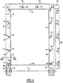
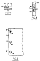
- FIGS. 6 and 7 illustrate an exemplary embodiment of such a tensioning system.
- the faces upper longitudinal sides 16 of the frame 10 of the cassette include elongated slots 54, which are radially oriented relative to a fixed point 56, located in the middle of a line joining the ends of the sides 16 opposite the side transverse 18, and corresponding to point 52 of the extendable frame 38.
- These openings 54 open into grooves formed in the longitudinal sides 16 of the frame 10, above the grooves 14 for receiving and guiding the bottom plate 10.
- These grooves 56 each receive a sliding bar 58 which itself comprises lights 60 oriented opposite to the lights 54.
- the bar 58 on the right has been shown outside the frame 10 for greater clarity, but it must of course be in the groove 56 on the corresponding side 16 of the frame.
- transverse bar 66 The bars 58 are joined together by a transverse bar 66 at their upper end.
- This transverse bar carries two pins 68 engaged in longitudinal slots 70 on the side 18 of the frame 10, and intended to engage in the slots 50 on the transverse side 42 of the extendable frame 38.
- the extendable frame 38 on which the membrane is fixed is placed on the upper face of the frame 10 so that the holes 48 of this extendable frame engage on the pins 64, and when the bars 58 by sliding in the grooves 56 as indicated above, the branches 40, 42 of the extendable frame 38 will elongate following the movement of the pins 64 in the slots 54 of the frame 10 and the membrane fixed on the frame will stretch substantially uniformly and radiant from point 52, which is then superimposed on point 56 of the frame 10.
- the elongation of the sides of the frame 38 is for example of the order of mm in transverse and from 2 to 3 mm in longitudinal , for a membrane of approximately 15 cm x 20 cm.
- the displacement of the bars 58 is ensured for example by cams 72 rotatably mounted about a transverse axis 74 and acting on the free end of the bars 58.
- a handle not shown, allows the cams 72 to rotate over a quarter in turn, for a displacement of the bars 58 of the order of a centimeter.
- each lumen 60 of each bar 58 is formed in a shoe 76 slidably mounted in a longitudinal housing 78 of the bar, and a spring or elastic element of compression 80 is arranged between the lower end of the housing 78 and the shoe 76.
- the extendable frame 38 is replaced by washers 82 of suitable material fixed at regular intervals on the periphery of the membrane 34, at least along the two long sides thereof, and comprising central orifices 84 corresponding to the holes 48 of the frame 38 to receive the pins 64 of the tension system.
- a liquid gel for example of agarose at a temperature of the order of 60 to 65 ° C.
- a liquid gel for example of agarose at a temperature of the order of 60 to 65 ° C.
- the membrane 34 on the periphery of which is fixed either the extendable frame 38 or the washers 82, is gradually deposited on the gel layer, from one end of the cassette, so that the holes 48 of the extendable frame 38 or the holes 84 of the washers 82 engage on the pins 64 of the tensioning mechanism.
- the cam control handle 72 is turned a quarter of a turn to move the bars 58 in the grooves of the frame 10, which puts the membrane 34 under low tension, by compensating for its possible elongation caused by impregnation by the gel and / or by the temperature of the gel, and by giving it perfect flatness.
- the gel is then allowed to solidify by cooling.
Landscapes
- Health & Medical Sciences (AREA)
- Life Sciences & Earth Sciences (AREA)
- Molecular Biology (AREA)
- Chemical & Material Sciences (AREA)
- Chemical Kinetics & Catalysis (AREA)
- Electrochemistry (AREA)
- Physics & Mathematics (AREA)
- Analytical Chemistry (AREA)
- Biochemistry (AREA)
- General Health & Medical Sciences (AREA)
- General Physics & Mathematics (AREA)
- Immunology (AREA)
- Pathology (AREA)
- Separation Using Semi-Permeable Membranes (AREA)
- Manufacture Of Porous Articles, And Recovery And Treatment Of Waste Products (AREA)
- Apparatus Associated With Microorganisms And Enzymes (AREA)
Claims (15)
- Verfahren zur Herstellung einer Platte aus Gel mit mikroporöser Membrane für die Trennung und die Übertragung von Makromolekülen durch Elektrophorese, beruhend auf dem Gießen des Gels in flüssiger Form auf eine Grundplatte (12), die einen Umfangsrahmen (10) trägt, dadurch gekennzeichnet, daß es ferner darauf beruht:- daß man progressiv bzw. fortschreitend auf das flüssige Gel eine trockene mikroporöse Membrane (34) legt,- daß man einen Zug auf den Umfang der Membrane (34) ausübt, um dieselbe in im wesentlichen gleichförmiger Art und Weise zu spannen,- und daß man das Gel sich verfestigen läßt, indem man die Membrane gespannt hält.
- Verfahren gemäß Anspruch 1, dadurch gekennzeichnet, daß es darauf beruht, daß man der Membrane (34) eine anfängliche mit Bezug auf das Gel konvex gekrümmte Form gibt und sie von einem Ende der Platte an auf das Gel legt, indem man ihr progressiv bzw. fortschreitend wieder eine ebene Form in dem Maße, in welchem sie in Kontakt mit dem Gel kommt, gibt.
- Verfahren gemäß Anspruch 1 oder 2, dadurch gekennzeichnet, daß es darauf beruht, daß man anfänglich den Umfang der Membrane (34) auf einem Rahmen (38) mit auszieh- bzw. streckbaren Seiten befestigt, dann, nachdem man die Membrane auf das flüssige Gel gelegt hat, die Seiten des genannten Rahmens verlängert bzw. dehnt, um die Membrane zu spannen.
- Verfahren gemäß Anspruch 3, dadurch gekennzeichnet, daß es darauf beruht, daß man die auszieh- bzw. streckbaren Seiten des Rahmens (38) während ihrer Verlängerung bzw. Dehnung gemäß Richtungen führt, die mit Bezug auf einen festen Punkt (52) ausstrahlen.
- Verfahren gemäß dem Anspruch 1 oder 2, dadurch gekennzeichnet, daß es darauf beruht, daß man Unterlagscheiben bzw. kleine Scheiben (82) auf dem Umfang der Membrane (34) wenigstens längs zweier entgegengesetzter Seiten derselben befestigt und danach einen Zug auf diese Unterlagscheiben bzw. kleinen Scheiben in Richtungen ausübt, die ausgehend von einem festen Punkt ausstrahlen, um die Membrane zu spannen.
- Verfahren gemäß einem der vorhergehenden Ansprüche, dadurch gekennzeichnet, daß es darauf beruht, daß man die vorgenannte Grundplatte (12) für die Benutzung der Platte wegnimmt.
- Einrichtung zur Herstellung einer Platte aus Gel mit mikroporöser Membrane, die zur Trennung und zur Übertragung von Makromolekülen durch Elektrophorese bestimmt ist, wobei die Einrichtung eine Grundplatte (12) umfaßt, die einen Umfangsrahmen (10) trägt, in dessen Inneres das Gel in flüssiger Form gegossen wird, wobei die Einrichtung dadurch gekennzeichnet ist, daß sie folgendes umfaßt:- Mittel (38, 82) zum Halt der Membrane (34) an ihrem Umfang,- Mittel zum Spannen, die auf die genannten Mittel zum Halt für das Spannen der auf das Gel gelegten Membrane wirken.
- Einrichtung gemäß dem Anspruch 7, dadurch gekennzeichnet, daß die Mittel zum Halt der Membrane einen Rahmen (38) mit auszieh- bzw. streckbaren Seiten umfassen, auf dem der Umfang der Membrane befestigt wird, zum Beispiel durch Punktschweißung oder -klebung.
- Einrichtung gemäß dem Anspruch 8, dadurch gekennzeichnet, daß der Rahmen (38) zum Halt der Membrane eine U-Konfiguration mit drei auszieh- bzw. streckbaren Seiten hat.
- Einrichtung gemäß dem Anspruch 7, dadurch gekennzeichnet, daß die Mittel zum Halt der Membrane Unterlagscheiben bzw. kleine Scheiben (82) umfassen, die in regelmäßigen Intervallen auf dem Umfang der Membrane wenigstens längs zweier entgegengesetzter Seiten derselben befestigt werden.
- Einrichtung gemäß einem der Ansprüche 8 bis 10 oder 8, dadurch gekennzeichnet, daß die Mittel zum Spannen der Membrane einen Zugmechanismus (58, 64), welcher auf die Mittel (38, 82) zum Halt der Membrane wirkt, und Mittel (54) zur Führung dieser Mittel zum Halt umfassen.
- Einrichtung gemäß dem Anspruch 11, dadurch gekennzeichnet, daß der vorgenannte Mechanismus folgendes umfaßt: Stäbchen (58), die zur Translation in Nuten (56) der Längsseiten (16) des Rahmens (10) der Grundplatte geführt sind, Pione bzw. Metallstücke (64), die mit den Mitteln zum Halt der Membrane zusammenwirken und in ausstrahlenden Öffnungen (54, 60) untergebracht sind, die jeweils in den vorgenannten Seiten (16) des Rahmens (10) und in den Stäbchen (58) ausgebildet sind, und Mittel zum Verlagern der Stäbchen (58) in Translation in den Nuten (56) der Seiten des Rahmens (10).
- Einrichtung gemäß dem Anspruch 12, dadurch gekennzeichnet, daß sie Mittel (76, 80) zum auto matischen Begrenzen der Spannung der Membrane auf einen vorbestimmten Wert umfaßt.
- Einrichtung gemäß einem der Ansprüche 7 bis 13, dadurch gekennzeichnet, daß die Grundplatte (12) abnehm- bzw. auswechselbar ist und an einem Ende einen Kamm (24, 26) für die Ausbildung von Schächten an einem Ende des gegossenen Gels trägt.
- Kassette mit Gel mit mikroporöser Membrane, zum Beispiel hergestellt mittels der Einrichtung gemäß einem der Ansprüche 7 bis 14, dadurch gekennzeichnet, daß sie einen Umfangsrahmen (10) umfaßt, der Mittel (14) für die Führung und zum Halt einer abnehm- bzw. auswechselbaren Grundplatte (12), auf welcher sich das Gel befindet, umfaßt, und Mittel (38, 82, 58, 64) für das Spannen der Membrane (34), die auf das Gel gelegt ist.
Applications Claiming Priority (3)
| Application Number | Priority Date | Filing Date | Title |
|---|---|---|---|
| FR9108578 | 1991-07-02 | ||
| FR9108578A FR2679033B1 (fr) | 1991-07-09 | 1991-07-09 | Procede et dispositif de fabrication d'une plaque de gel a membrane microporeuse destinee a la separation et au transfert de macromolecules par electrophorese, et cassette de gel ainsi obtenue. |
| PCT/FR1992/000650 WO1993001491A1 (fr) | 1991-07-09 | 1992-07-08 | Procede et dispositif de fabrication d'une plaque de gel a membrane microporeuse et cassette de gel |
Publications (2)
| Publication Number | Publication Date |
|---|---|
| EP0548335A1 EP0548335A1 (de) | 1993-06-30 |
| EP0548335B1 true EP0548335B1 (de) | 1996-04-17 |
Family
ID=9414852
Family Applications (1)
| Application Number | Title | Priority Date | Filing Date |
|---|---|---|---|
| EP92915601A Expired - Lifetime EP0548335B1 (de) | 1991-07-09 | 1992-07-08 | Verfahren und Vorrichtung zur Herstellung einer Gelplatte mit mikroporöser Membran und Gelkassette |
Country Status (10)
| Country | Link |
|---|---|
| US (1) | US5415752A (de) |
| EP (1) | EP0548335B1 (de) |
| JP (1) | JPH06501104A (de) |
| KR (1) | KR930702676A (de) |
| AT (1) | ATE137019T1 (de) |
| AU (1) | AU656621B2 (de) |
| CA (1) | CA2091351A1 (de) |
| DE (1) | DE69209997T2 (de) |
| FR (1) | FR2679033B1 (de) |
| WO (1) | WO1993001491A1 (de) |
Families Citing this family (4)
| Publication number | Priority date | Publication date | Assignee | Title |
|---|---|---|---|---|
| US5433837A (en) * | 1993-08-27 | 1995-07-18 | E. I. Du Pont De Nemours And Company | Gel cassette for enhanced electrophoretic separation and processes for the preparation thereof |
| US6969455B1 (en) | 2003-01-22 | 2005-11-29 | Joel Helfer | Electrophoresis frame for gel slabs with different thickness holder plates |
| WO2014007720A1 (en) * | 2012-05-31 | 2014-01-09 | Ge Healthcare Bio-Sciences Ab | An electrophoresis gel unit comprising a flat gel member attached to a support |
| US20210164936A1 (en) * | 2019-11-29 | 2021-06-03 | Smobio Technology, Inc. | Electrophoresis gel cassette |
Family Cites Families (12)
| Publication number | Priority date | Publication date | Assignee | Title |
|---|---|---|---|---|
| US3767560A (en) * | 1966-09-13 | 1973-10-23 | F Elevitch | Method and apparatus for forming electrophoresis apparatus and the like |
| US3808118A (en) * | 1969-03-13 | 1974-04-30 | Helena Lab Corp | Microporous support medium |
| DE3024288C2 (de) * | 1980-06-27 | 1982-03-25 | Europäisches Laboratorium für Molekularbiologie (EMBL), 6900 Heidelberg | Verfahren und Vorrichtung zur Herstellung dünner Schichten |
| US4381168A (en) * | 1981-01-16 | 1983-04-26 | Beckman Instruments, Inc. | Method and apparatus for separating a layer of flexible material from a surface |
| GB8605444D0 (en) * | 1986-03-05 | 1986-04-09 | Automated Microbiology Systems | Electrophoresis gel |
| US4830725A (en) * | 1987-08-04 | 1989-05-16 | Life Technologies, Inc. | Electrophoresis apparatus |
| US4812216A (en) * | 1987-08-28 | 1989-03-14 | Bios Corporation | Method of handling and transporting a transfer membrane used in a blotting apparatus |
| JPH01185439A (ja) * | 1988-01-20 | 1989-07-25 | Fuji Photo Film Co Ltd | 電気泳動ゲルシートの製造方法 |
| US4883597A (en) * | 1988-10-28 | 1989-11-28 | Brandeis University | Hydrophobic membrane for drying gel matrices |
| US4954236A (en) * | 1989-06-28 | 1990-09-04 | Bio-Rad Laboratories, Inc. | Apparatus and method for gel casting and electrophoresis in a single enclosure |
| DE3935020A1 (de) * | 1989-10-20 | 1991-04-25 | Serva Feinbiochem Gmbh & Co | Verbesserte elektrophoresegele aus agarose |
| FR2670129B1 (fr) * | 1990-12-10 | 1993-04-02 | Bertin & Cie | Procede de preparation d'une membrane garnie d'une couche d'un gel et cadre de support d'une telle membrane concu pour la mise en óoeuvre de ce procede. |
-
1991
- 1991-07-09 FR FR9108578A patent/FR2679033B1/fr not_active Expired - Fee Related
-
1992
- 1992-07-08 JP JP5502038A patent/JPH06501104A/ja active Pending
- 1992-07-08 CA CA002091351A patent/CA2091351A1/fr not_active Abandoned
- 1992-07-08 KR KR1019930700697A patent/KR930702676A/ko not_active Withdrawn
- 1992-07-08 US US07/975,941 patent/US5415752A/en not_active Expired - Fee Related
- 1992-07-08 AU AU23281/92A patent/AU656621B2/en not_active Ceased
- 1992-07-08 EP EP92915601A patent/EP0548335B1/de not_active Expired - Lifetime
- 1992-07-08 DE DE69209997T patent/DE69209997T2/de not_active Expired - Fee Related
- 1992-07-08 WO PCT/FR1992/000650 patent/WO1993001491A1/fr not_active Ceased
- 1992-07-08 AT AT92915601T patent/ATE137019T1/de not_active IP Right Cessation
Also Published As
| Publication number | Publication date |
|---|---|
| FR2679033A1 (fr) | 1993-01-15 |
| DE69209997T2 (de) | 1996-09-26 |
| AU656621B2 (en) | 1995-02-09 |
| WO1993001491A1 (fr) | 1993-01-21 |
| AU2328192A (en) | 1993-02-11 |
| US5415752A (en) | 1995-05-16 |
| KR930702676A (ko) | 1993-09-09 |
| EP0548335A1 (de) | 1993-06-30 |
| JPH06501104A (ja) | 1994-01-27 |
| DE69209997D1 (de) | 1996-05-23 |
| ATE137019T1 (de) | 1996-05-15 |
| FR2679033B1 (fr) | 1993-11-05 |
| CA2091351A1 (fr) | 1993-01-10 |
Similar Documents
| Publication | Publication Date | Title |
|---|---|---|
| FR2596948A1 (fr) | Appareil a ebrancher les troncs d'arbres | |
| FR2596947A1 (fr) | Dispositif d'avance pour deplacement le long d'un tronc d'arbre | |
| FR2744598A1 (fr) | Procede et appareil de production d'un aliment cylindrique, et aliment cylindrique | |
| EP0346177B1 (de) | Befestigungsvorrichtung für eine Platte oder ähnliches im inneren eines Rahmens | |
| EP0548335B1 (de) | Verfahren und Vorrichtung zur Herstellung einer Gelplatte mit mikroporöser Membran und Gelkassette | |
| EP2112106B1 (de) | Verfahren und Vorrichtung zum Stoßschneiden und -verkleben für Rundschälmaschine | |
| EP0592298B1 (de) | Verfahren und Vorrichtung zur Herstellung einer Gelplatte mit mikroporöser Membran zur Trennung und Übertragung von Makromolekülen durch Electroforese | |
| FR2587593A1 (fr) | Appareillage et procede pour l'epluchage partiel du mais sweet corn frais. | |
| FR2503683A1 (fr) | Dispositif de devidage automatique d'une bande d'etoffe provenant d'un rouleau monte sur un support multiple | |
| EP0490789B1 (de) | Verfahren und Vorrichtung zur Herstellung von halbdurchlässigen Hohlfaserbündeln für Membranvorrichtungen | |
| CA1135516A (fr) | Chaine a un seul sens de courbure et application a une main courante | |
| CH618940A5 (de) | ||
| FR2545463A1 (fr) | Appareil de collage de bandes | |
| FR2724294A1 (fr) | Machine pour le bridage des volailles | |
| FR2716333A1 (fr) | Dispositif de pose de gazon précultivé en bandes. | |
| FR2612827A1 (fr) | Machine de deroulage de bille de bois pourvue de rouleaux de support rotatifs et mobiles | |
| FR2632832A1 (fr) | Procede et appareil pour former des espaces depourvus d'elements d'accouplement dans une chaine de fermeture a glissiere | |
| BE1004237A4 (fr) | Procede de fabrication d'un profile pourvu d'une barriere thermique et installation pour la mise en oeuvre de ce procede. | |
| FR2693444A1 (fr) | Dispositif enrouleur de papier toilette. | |
| EP0292490B1 (de) | Verfahren und vorrichtung zum greifen eines biegsamen gegenstandes auf einem stapel | |
| FR2493572A1 (fr) | Procede d'obtention d'images composites, a facettes, appareil pour la mise en oeuvre de ce procede, produits obtenus et utilisations de ces produits | |
| FR2722949A1 (fr) | Dispositif de detroquage de tuiles de collecte de naissains d'huitres et tuiles de collecte associees | |
| FR2518008A1 (fr) | Procede et installation de coulage automatique notamment de pieces plates ou predalles realise en un materiel durcissable tel que du beton ou analogue | |
| FR2751952A1 (fr) | Installation permettant de reconditionner sous la forme d'un enroulement une matiere en bande, telle qu'une etoffe | |
| FR2655591A1 (fr) | Dispositif pour conserver l'aplat d'une bande de carton entre deux elements consecutifs d'une spiraleuse. |
Legal Events
| Date | Code | Title | Description |
|---|---|---|---|
| PUAI | Public reference made under article 153(3) epc to a published international application that has entered the european phase |
Free format text: ORIGINAL CODE: 0009012 |
|
| 17P | Request for examination filed |
Effective date: 19930212 |
|
| AK | Designated contracting states |
Kind code of ref document: A1 Designated state(s): AT BE CH DE DK ES FR GB GR IT LI LU MC NL SE |
|
| 17Q | First examination report despatched |
Effective date: 19950602 |
|
| GRAH | Despatch of communication of intention to grant a patent |
Free format text: ORIGINAL CODE: EPIDOS IGRA |
|
| GRAA | (expected) grant |
Free format text: ORIGINAL CODE: 0009210 |
|
| AK | Designated contracting states |
Kind code of ref document: B1 Designated state(s): AT BE CH DE DK ES FR GB GR IT LI LU MC NL SE |
|
| PG25 | Lapsed in a contracting state [announced via postgrant information from national office to epo] |
Ref country code: NL Free format text: LAPSE BECAUSE OF FAILURE TO SUBMIT A TRANSLATION OF THE DESCRIPTION OR TO PAY THE FEE WITHIN THE PRESCRIBED TIME-LIMIT Effective date: 19960417 Ref country code: IT Free format text: LAPSE BECAUSE OF FAILURE TO SUBMIT A TRANSLATION OF THE DESCRIPTION OR TO PAY THE FEE WITHIN THE PRE;WARNING: LAPSES OF ITALIAN PATENTS WITH EFFECTIVE DATE BEFORE 2007 MAY HAVE OCCURRED AT ANY TIME BEFORE 2007. THE CORRECT EFFECTIVE DATE MAY BE DIFFERENT FROM THE ONE RECORDED.SCRIBED TIME-LIMIT Effective date: 19960417 Ref country code: GR Free format text: LAPSE BECAUSE OF FAILURE TO SUBMIT A TRANSLATION OF THE DESCRIPTION OR TO PAY THE FEE WITHIN THE PRESCRIBED TIME-LIMIT Effective date: 19960417 Ref country code: GB Effective date: 19960417 Ref country code: ES Free format text: THE PATENT HAS BEEN ANNULLED BY A DECISION OF A NATIONAL AUTHORITY Effective date: 19960417 Ref country code: DK Effective date: 19960417 Ref country code: AT Effective date: 19960417 |
|
| REF | Corresponds to: |
Ref document number: 137019 Country of ref document: AT Date of ref document: 19960515 Kind code of ref document: T |
|
| REF | Corresponds to: |
Ref document number: 69209997 Country of ref document: DE Date of ref document: 19960523 |
|
| PG25 | Lapsed in a contracting state [announced via postgrant information from national office to epo] |
Ref country code: SE Effective date: 19960717 |
|
| PG25 | Lapsed in a contracting state [announced via postgrant information from national office to epo] |
Ref country code: LU Free format text: LAPSE BECAUSE OF NON-PAYMENT OF DUE FEES Effective date: 19960731 Ref country code: LI Effective date: 19960731 Ref country code: CH Effective date: 19960731 Ref country code: BE Effective date: 19960731 |
|
| NLV1 | Nl: lapsed or annulled due to failure to fulfill the requirements of art. 29p and 29m of the patents act | ||
| GBV | Gb: ep patent (uk) treated as always having been void in accordance with gb section 77(7)/1977 [no translation filed] |
Effective date: 19960417 |
|
| BERE | Be: lapsed |
Owner name: BERTIN & CIE Effective date: 19960731 |
|
| PG25 | Lapsed in a contracting state [announced via postgrant information from national office to epo] |
Ref country code: MC Effective date: 19970131 |
|
| PLBE | No opposition filed within time limit |
Free format text: ORIGINAL CODE: 0009261 |
|
| STAA | Information on the status of an ep patent application or granted ep patent |
Free format text: STATUS: NO OPPOSITION FILED WITHIN TIME LIMIT |
|
| REG | Reference to a national code |
Ref country code: CH Ref legal event code: PL |
|
| 26N | No opposition filed | ||
| PGFP | Annual fee paid to national office [announced via postgrant information from national office to epo] |
Ref country code: FR Payment date: 19970626 Year of fee payment: 6 |
|
| PGFP | Annual fee paid to national office [announced via postgrant information from national office to epo] |
Ref country code: DE Payment date: 19970707 Year of fee payment: 6 |
|
| PG25 | Lapsed in a contracting state [announced via postgrant information from national office to epo] |
Ref country code: FR Free format text: LAPSE BECAUSE OF NON-PAYMENT OF DUE FEES Effective date: 19990331 |
|
| PG25 | Lapsed in a contracting state [announced via postgrant information from national office to epo] |
Ref country code: DE Free format text: LAPSE BECAUSE OF NON-PAYMENT OF DUE FEES Effective date: 19990501 |
|
| REG | Reference to a national code |
Ref country code: FR Ref legal event code: ST |