EP0548397B1 - Dispositif pour la séparation de particules contenant des matières solides à partir de suspensions aqueuses - Google Patents
Dispositif pour la séparation de particules contenant des matières solides à partir de suspensions aqueuses Download PDFInfo
- Publication number
- EP0548397B1 EP0548397B1 EP91122142A EP91122142A EP0548397B1 EP 0548397 B1 EP0548397 B1 EP 0548397B1 EP 91122142 A EP91122142 A EP 91122142A EP 91122142 A EP91122142 A EP 91122142A EP 0548397 B1 EP0548397 B1 EP 0548397B1
- Authority
- EP
- European Patent Office
- Prior art keywords
- suspension
- separator
- filter
- porous
- inlet
- Prior art date
- Legal status (The legal status is an assumption and is not a legal conclusion. Google has not performed a legal analysis and makes no representation as to the accuracy of the status listed.)
- Expired - Lifetime
Links
Images

Classifications
-
- B—PERFORMING OPERATIONS; TRANSPORTING
- B01—PHYSICAL OR CHEMICAL PROCESSES OR APPARATUS IN GENERAL
- B01D—SEPARATION
- B01D29/00—Filters with filtering elements stationary during filtration, e.g. pressure or suction filters, not covered by groups B01D24/00 - B01D27/00; Filtering elements therefor
- B01D29/11—Filters with filtering elements stationary during filtration, e.g. pressure or suction filters, not covered by groups B01D24/00 - B01D27/00; Filtering elements therefor with bag, cage, hose, tube, sleeve or like filtering elements
- B01D29/13—Supported filter elements
- B01D29/23—Supported filter elements arranged for outward flow filtration
- B01D29/25—Supported filter elements arranged for outward flow filtration open-ended the arrival of the mixture to be filtered and the discharge of the concentrated mixture are situated on both opposite sides of the filtering element
-
- B—PERFORMING OPERATIONS; TRANSPORTING
- B01—PHYSICAL OR CHEMICAL PROCESSES OR APPARATUS IN GENERAL
- B01D—SEPARATION
- B01D29/00—Filters with filtering elements stationary during filtration, e.g. pressure or suction filters, not covered by groups B01D24/00 - B01D27/00; Filtering elements therefor
- B01D29/50—Filters with filtering elements stationary during filtration, e.g. pressure or suction filters, not covered by groups B01D24/00 - B01D27/00; Filtering elements therefor with multiple filtering elements, characterised by their mutual disposition
- B01D29/56—Filters with filtering elements stationary during filtration, e.g. pressure or suction filters, not covered by groups B01D24/00 - B01D27/00; Filtering elements therefor with multiple filtering elements, characterised by their mutual disposition in series connection
- B01D29/58—Filters with filtering elements stationary during filtration, e.g. pressure or suction filters, not covered by groups B01D24/00 - B01D27/00; Filtering elements therefor with multiple filtering elements, characterised by their mutual disposition in series connection arranged concentrically or coaxially
-
- B—PERFORMING OPERATIONS; TRANSPORTING
- B01—PHYSICAL OR CHEMICAL PROCESSES OR APPARATUS IN GENERAL
- B01D—SEPARATION
- B01D29/00—Filters with filtering elements stationary during filtration, e.g. pressure or suction filters, not covered by groups B01D24/00 - B01D27/00; Filtering elements therefor
- B01D29/88—Filters with filtering elements stationary during filtration, e.g. pressure or suction filters, not covered by groups B01D24/00 - B01D27/00; Filtering elements therefor having feed or discharge devices
- B01D29/90—Filters with filtering elements stationary during filtration, e.g. pressure or suction filters, not covered by groups B01D24/00 - B01D27/00; Filtering elements therefor having feed or discharge devices for feeding
- B01D29/902—Filters with filtering elements stationary during filtration, e.g. pressure or suction filters, not covered by groups B01D24/00 - B01D27/00; Filtering elements therefor having feed or discharge devices for feeding containing fixed liquid displacement elements or cores
-
- B—PERFORMING OPERATIONS; TRANSPORTING
- B01—PHYSICAL OR CHEMICAL PROCESSES OR APPARATUS IN GENERAL
- B01D—SEPARATION
- B01D29/00—Filters with filtering elements stationary during filtration, e.g. pressure or suction filters, not covered by groups B01D24/00 - B01D27/00; Filtering elements therefor
- B01D29/88—Filters with filtering elements stationary during filtration, e.g. pressure or suction filters, not covered by groups B01D24/00 - B01D27/00; Filtering elements therefor having feed or discharge devices
- B01D29/90—Filters with filtering elements stationary during filtration, e.g. pressure or suction filters, not covered by groups B01D24/00 - B01D27/00; Filtering elements therefor having feed or discharge devices for feeding
- B01D29/908—Filters with filtering elements stationary during filtration, e.g. pressure or suction filters, not covered by groups B01D24/00 - B01D27/00; Filtering elements therefor having feed or discharge devices for feeding provoking a tangential stream
Definitions
- the invention relates to a device for separating solid particles from aqueous suspensions by filtration with continuous cleaning of the filter surfaces, the suspension being rotated via an inlet in a plane perpendicular to gravity and under the action of gravity a water curtain is formed which is porous , cylindrical filter surface 6,7 of a separator 1 is guided, along which the aqueous suspension with the solid particles accumulating in the rotating water curtain runs downwards, while the cleaned water passes through the porous filter surface 6,7 and is discharged from there, and the Inlet in front of the separator 1 consists of an inlet nozzle 2 which is essentially tubular.
- a device for separating solid particles from aqueous suspensions of the type mentioned at the outset is known from DE-A-27 08 135.
- a vacuum lock is additionally provided in the known device, which, in conjunction with a vacuum source, ensures that the suspension added forms a closed layer in the separator.
- the known device is designed to be vacuum-tight from the inlet area to the solids discharge.
- a method for rainwater detection from a downpipe coming from the gutter in which the water is passed over a cover part through a conical sieve device and rainwater separation device, the rainwater being divided into one cleaned fraction and into a fraction enriched with dirt particles.
- the division of the rainwater into these fractions is achieved through the use of adhesive separating forces, which derive most of the water from the rainwater separating device.
- the separation takes place in a device consisting of an expanded metal body covering the entire surface of the screen device, the surface of which is increased by roughening.
- Rainwater drainage direction and filter flow direction are in one line.
- the known method according to DE-A-38 12 136 has proven itself in practice, but it is unsuitable for the introduction of rainwater or other suspensions arriving transversely to the flow and filter direction.
- the known device could therefore only be used in some of the rainwater detection devices which lead vertically down from the roof plane and in which there is still enough space to carry out the separation into a device arranged vertically.
- the object of the present invention is to overcome the disadvantages of the rainwater detection devices described above to avoid or separation of solid particles from suspensions and to enable an effective separation of solid particles from horizontally introduced suspensions even at low flow rates without the use of a vacuum.
- the horizontally inflowing suspension is set into a swirl flow beforehand, as a result of which an even more intensive pressing against the side walls of the separator and subsequently of the cylindrical filter surface is achieved.
- the screening device preferably consisting of a double-acting filter element which has an increased formation of adhesive forces.
- the filter element has finely formed capillaries that pull through the sieve body and thus enable solids to be separated.
- the particle size which can be achieved in the separating device according to the invention is below 50 »m.
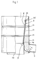
- a separator 1 is shown with a drain port 3. Inside there is a filter element 5, which has a smooth filter outer surface 6 and a roughened filter inner surface 7.
- Baffles ensure that the flow arriving via the inlet connection 2, which is preferably designed as a swirl flow, is converted from a radial / tangential introduction to a predominantly tangential flow, which is applied as a rotational flow to the inside of the surface line.
- the suspension which is set in rotation, is thus pressed against the surface line by means of the guide plates and thus forms a flow thread which, under the action of gravity, changes into a water curtain further down.
- the flow rate of the suspension is further increased by the inlet funnel 12, which forms the transition to the filter element 5.
- the suspension set in a rotating flow is passed as a water curtain over the actual separating surface, which consists of a smooth, internal filter surface 6 and a rough external filter surface 7.
- the solids are filtered out of the suspension up to a size of 100 »m. This is done by pressing the rotationally suspended suspension against smooth, fine-pored filter surfaces 6 under the influence of the peripheral speed, all particles with a diameter of> 100 »being retained, while the cleaned solution runs downwards on the rough filter surface 7.
- the pore channels are alternately opened and closed, so that a pulsation effect in connection with the pressure acting from the smooth filter surface 6 arises. This pressure fluctuation has the effect that any solid particles adhering to the smooth filter surface 6 are detached and removed from the bottom of the separator 1.
- the cleaned solution is discharged from the separator via the outlet nozzle 3.
- the concentrated, solids-containing suspension is disposed of via the main channel 14, further treatment of the suspension optionally being carried out by downstream separation stages which operate according to the method according to the invention.
- the filter element 5 consists of a conical tube, a truncated cone 15 being arranged on the input side and a cone tip 16 being arranged on the output side.
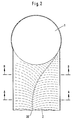
- the swirl flow in the inlet connection 2 can be generated by a depression in the form of a groove 30.
- 2 shows a cross section through the separator 1 at the level of the inlet connector 2 in a basic form, the channel 30 being guided in the flow course from the central axis of the inlet connector 2 to the inner edge of the inlet zone.
- the rainwater flowing in at A-A is thus led to the edge of the separator 1 by a swirling flow.
- FIGS. 2 and 3 show cross sections through the inlet connection 2 at the level of the section lines A-A and B-B.
- the flow channel is displaced by changing the tube sheet 32, so that the inflowing rainwater is led from the left edge of the image to the right edge of the image.
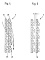
- two layers or more layers of the filter element designed according to the invention can be placed one inside the other. This means that the water flowing through the one filter element enters a new filter element on the outlet side and is deflected there, again due to the adhesive bond.
- the multiple series connection of filter elements thus enables a significant increase in the deflection angle and thus improves the filter effect.
- the water emerging from the separator 1 passes between the knobs 38 via a porous filter layer 37 and from there, in turn, into a second porous layer 39 between the knobs 40. If the distance A between the knobs 38 and the second porous filter layer 39 is increased to 1 to 2 mm, the suction effect or the adhesive forces between the filter elements is improved. This increases the filter effect.
Landscapes
- Chemical & Material Sciences (AREA)
- Chemical Kinetics & Catalysis (AREA)
- Filtration Of Liquid (AREA)
- Separation Of Suspended Particles By Flocculating Agents (AREA)
- Centrifugal Separators (AREA)
Claims (3)
- Dispositif pour séparer de suspensions aqueuses des particules de matières solides par filtration avec nettoyage en continu des faces filtrantes, la suspension étant, au moyen d'un organe d'admission, mise en rotation dans un plan perpendiculaire à la force centrifuge et un rideau d'eau se formant sous l'action de la force centrifuge, qui est dirigé sur une face filtrante poreuse cylindrique (6, 7) d'un séparateur (1), le long de laquelle la suspension aqueuse s'écoule vers le bas avec les particules de matières solides s'enrichissant dans le rideau d'eau rotatif, tandis que l'eau épurée traverse la face filtrante poreuse (6, 7) puis est évacuée, et l'organe d'admission précédant le séparateur (1) étant constitué d'un piquage d'admission (2) qui est réalisé essentiellement tubulaire, caractérisé en ce que le piquage d'admission (2) présente, sur le fond intérieur du tube qui est tourné vers l'extrémité d'évacuation du séparateur (1), une rigole (30) qui s'étend dans la direction d'écoulement depuis l'axe médian du piquage d'admission (2) jusqu'au bord extérieur du point de jonction entre le piquage d'admission (2) et le séparateur (1), un entonnoir (12) allant en se rétrécissant étant disposé à la transition entre le piquage d'admission (2) et le séparateur (1), et en ce que la face filtrante (6, 7) pourvue de pores ou d'ouvertures (13) est réalisée rugueuse sur le côté opposé à la suspension et lisse sur le côté tourné vers la suspension.
- Dispositif selon la revendication 1, caractérisé en ce que la face filtrante (7) est constituée d'une surface poreuse (37) à capillaires fins, directement tournée vers la suspension et sur le dos de laquelle sont disposés, dans la direction d'écoulement, des bossages (38) en forme de nopes ou des arêtes vives.
- Dispositif selon l'une des revendications précédentes, caractérisé en ce qu'une deuxième couche poreuse (39) est en contact avec les bossages (38) en forme de nopes et présente elle-même, sur le côté opposé, des deuxièmes bossages (40) en forme de nopes.
Priority Applications (4)
| Application Number | Priority Date | Filing Date | Title |
|---|---|---|---|
| DE59105200T DE59105200D1 (de) | 1991-12-23 | 1991-12-23 | yorrichtung zur Trennung von feststoffhaltigen Partikeln aus wässrigen Suspensionen. |
| AT91122142T ATE120977T1 (de) | 1991-12-23 | 1991-12-23 | Yorrichtung zur trennung von feststoffhaltigen partikeln aus wässrigen suspensionen. |
| DK91122142.2T DK0548397T3 (da) | 1991-12-23 | 1991-12-23 | Fremgangsmåde og indretning til adskillelse af faststofholdige partikler fra vandige suspensioner |
| EP91122142A EP0548397B1 (fr) | 1991-12-23 | 1991-12-23 | Dispositif pour la séparation de particules contenant des matières solides à partir de suspensions aqueuses |
Applications Claiming Priority (1)
| Application Number | Priority Date | Filing Date | Title |
|---|---|---|---|
| EP91122142A EP0548397B1 (fr) | 1991-12-23 | 1991-12-23 | Dispositif pour la séparation de particules contenant des matières solides à partir de suspensions aqueuses |
Publications (2)
| Publication Number | Publication Date |
|---|---|
| EP0548397A1 EP0548397A1 (fr) | 1993-06-30 |
| EP0548397B1 true EP0548397B1 (fr) | 1995-04-12 |
Family
ID=8207473
Family Applications (1)
| Application Number | Title | Priority Date | Filing Date |
|---|---|---|---|
| EP91122142A Expired - Lifetime EP0548397B1 (fr) | 1991-12-23 | 1991-12-23 | Dispositif pour la séparation de particules contenant des matières solides à partir de suspensions aqueuses |
Country Status (4)
| Country | Link |
|---|---|
| EP (1) | EP0548397B1 (fr) |
| AT (1) | ATE120977T1 (fr) |
| DE (1) | DE59105200D1 (fr) |
| DK (1) | DK0548397T3 (fr) |
Families Citing this family (8)
| Publication number | Priority date | Publication date | Assignee | Title |
|---|---|---|---|---|
| DE9408254U1 (de) * | 1994-05-19 | 1994-07-28 | Winkler, Norbert, 63699 Kefenrod | Filtereinrichtung |
| DE29718949U1 (de) * | 1997-09-11 | 1998-01-08 | Ing. Walter Hengst GmbH & Co KG, 48147 Münster | Filter, insbesondere Regenwasserfilter |
| DE29716642U1 (de) * | 1997-09-17 | 1997-11-06 | Winkler, Norbert, 63699 Kefenrod | Trenn- und Abscheidevorrichtung |
| DE19818427C5 (de) * | 1998-04-24 | 2005-07-07 | Kruk Kunststoffe Gmbh | Filter zum Einsatz in einer Vorrichtung zum Trennen von Feststoffpartikeln aus wässrigen Suspensionen, insbesondere aus Regenwasser |
| DE19847655A1 (de) * | 1998-10-15 | 2000-04-20 | Gep Umwelttechnik Gmbh | Zisternenfilter |
| DE102012017728A1 (de) * | 2012-09-07 | 2014-04-03 | Wisy Ag Haustechniksysteme, Filtertechnik | Wasserfilter, insbesondere Regenwasserfilter mit einem Sieb |
| DE102012022586A1 (de) * | 2012-11-20 | 2014-05-22 | Wisy Ag Haustechniksysteme, Filtertechnik | Regenwasserabscheider für ein Fallrohr |
| DE102013002013A1 (de) * | 2013-02-06 | 2014-08-07 | Wisy Ag Haustechniksysteme, Filtertechnik | System von Bauteilen, die zusammengesetzt einen Regenwasserabscheider für ein Fallrohr bilden |
Family Cites Families (5)
| Publication number | Priority date | Publication date | Assignee | Title |
|---|---|---|---|---|
| FI40358B (fr) * | 1959-05-05 | 1968-09-02 | Ingersoll Rand World Trade Ltd | |
| DE1245264B (de) * | 1963-02-13 | 1967-07-20 | Starcosa G M B H & Co | Siebvorrichtung, bestehend aus einem als nach unten verjuengter Rotationshohlkoerperausgebildeten Sieb mit senkrechter Achse |
| DE2708135A1 (de) * | 1977-02-25 | 1978-08-31 | Schauenburg Masch | Vorrichtung zur aufbereitung von truebe |
| DE3812136A1 (de) * | 1987-07-21 | 1989-02-02 | Norbert Winkler | Verfahren und vorrichtung zur regenwassererfassung |
| DE3835326A1 (de) * | 1988-10-17 | 1990-04-19 | Koller Josef | Vorrichtung zum abscheiden und sammeln von feststoffen aus einem fluessigkeitsstrom |
-
1991
- 1991-12-23 EP EP91122142A patent/EP0548397B1/fr not_active Expired - Lifetime
- 1991-12-23 DK DK91122142.2T patent/DK0548397T3/da active
- 1991-12-23 AT AT91122142T patent/ATE120977T1/de not_active IP Right Cessation
- 1991-12-23 DE DE59105200T patent/DE59105200D1/de not_active Expired - Fee Related
Also Published As
| Publication number | Publication date |
|---|---|
| EP0548397A1 (fr) | 1993-06-30 |
| DK0548397T3 (da) | 1995-07-10 |
| ATE120977T1 (de) | 1995-04-15 |
| DE59105200D1 (de) | 1995-05-18 |
Similar Documents
| Publication | Publication Date | Title |
|---|---|---|
| EP1062047B1 (fr) | Separateur cyclone | |
| EP3117904B1 (fr) | Dispositif de separation pour de petites parties d'un flux de fluide | |
| DE69816068T2 (de) | Vorrichtung zur abtrennung von feststoffen aus einer flüssigkeit | |
| EP0548397A1 (fr) | Dispositif pour la séparation de particules contenant des matières solides à partir de suspensions aqueuses | |
| DE3524640C2 (de) | Vorrichtung zur Behandlung von Flüssigkeiten | |
| EP0398864B1 (fr) | Procédé et dispositif de séparation de matières d'un milieu | |
| DE2038871A1 (de) | Vorrichtung zum Filtrieren von gasfoermigen Medien | |
| DE3523998C2 (fr) | ||
| CN107050967A (zh) | 一种具有收集功能的过滤装置 | |
| DE102004060981A1 (de) | Staubsammelvorrichtung für einen Staubsauger | |
| EP3758827A1 (fr) | Séparateur à coalescence, en particulier destiné à être utilisé dans un système d'air comprimé de compresseur, système d'air comprimé de compresseur et utilisation d'un séparateur à coalescence | |
| DE69107522T2 (de) | Vorrichtung zum Abführen des Waschwassers aus einem Filter mit körnigem Filtermaterial und gleichzeitigem Waschen mit Wasser und Luft. | |
| EP1368132B1 (fr) | Dispositif de revetement destine a une longue piece | |
| DE2945951C2 (de) | Verfahren und Einrichtung zum Stoftrennen mittels Fliehkraft | |
| EP0682968B1 (fr) | Installation de filtrage | |
| DE19855256A1 (de) | Mikroseparator | |
| DE102010041100A1 (de) | Entgasung | |
| DE19807068A1 (de) | Fallrohrfilter | |
| DE2421143A1 (de) | Verfahren und nasswaescher zum abscheiden von staubpartikeln aus einem luft- bzw. gasstrom | |
| DE2645580C2 (de) | Steuerkopf für Zellendrehfilter für industrielle Verwendung | |
| DE3613598A1 (de) | Vorrichtung zur feinabscheidung von fluessigkeit aus einem fluidstrom | |
| AT521979B1 (de) | Vorrichtung zum Filtern von Partikeln | |
| DE4029611C1 (en) | Dry gas scrubbing system - removes large particles in dry separator and has electrostatic device | |
| CH674950A5 (fr) | ||
| DE879677C (de) | Vorrichtung und Verfahren zum Abscheiden von in einer Fluessigkeit suspendierten Faserstoffen |
Legal Events
| Date | Code | Title | Description |
|---|---|---|---|
| PUAI | Public reference made under article 153(3) epc to a published international application that has entered the european phase |
Free format text: ORIGINAL CODE: 0009012 |
|
| AK | Designated contracting states |
Kind code of ref document: A1 Designated state(s): AT BE CH DE DK ES FR GB GR IT LI LU MC NL SE |
|
| 17P | Request for examination filed |
Effective date: 19930619 |
|
| RBV | Designated contracting states (corrected) |
Designated state(s): AT BE CH DE DK FR IT LI LU MC |
|
| 17Q | First examination report despatched |
Effective date: 19931229 |
|
| GRAA | (expected) grant |
Free format text: ORIGINAL CODE: 0009210 |
|
| AK | Designated contracting states |
Kind code of ref document: B1 Designated state(s): AT BE CH DE DK FR IT LI LU MC |
|
| REF | Corresponds to: |
Ref document number: 120977 Country of ref document: AT Date of ref document: 19950415 Kind code of ref document: T |
|
| REF | Corresponds to: |
Ref document number: 59105200 Country of ref document: DE Date of ref document: 19950518 |
|
| ITF | It: translation for a ep patent filed | ||
| REG | Reference to a national code |
Ref country code: DK Ref legal event code: T3 |
|
| ET | Fr: translation filed | ||
| PLBE | No opposition filed within time limit |
Free format text: ORIGINAL CODE: 0009261 |
|
| STAA | Information on the status of an ep patent application or granted ep patent |
Free format text: STATUS: NO OPPOSITION FILED WITHIN TIME LIMIT |
|
| 26N | No opposition filed | ||
| PGFP | Annual fee paid to national office [announced via postgrant information from national office to epo] |
Ref country code: MC Payment date: 19971223 Year of fee payment: 7 |
|
| PG25 | Lapsed in a contracting state [announced via postgrant information from national office to epo] |
Ref country code: MC Free format text: LAPSE BECAUSE OF NON-PAYMENT OF DUE FEES Effective date: 19990630 |
|
| PGFP | Annual fee paid to national office [announced via postgrant information from national office to epo] |
Ref country code: FR Payment date: 20001128 Year of fee payment: 10 Ref country code: DK Payment date: 20001128 Year of fee payment: 10 |
|
| PGFP | Annual fee paid to national office [announced via postgrant information from national office to epo] |
Ref country code: AT Payment date: 20001214 Year of fee payment: 10 |
|
| PGFP | Annual fee paid to national office [announced via postgrant information from national office to epo] |
Ref country code: CH Payment date: 20001221 Year of fee payment: 10 |
|
| PGFP | Annual fee paid to national office [announced via postgrant information from national office to epo] |
Ref country code: LU Payment date: 20010102 Year of fee payment: 10 |
|
| PGFP | Annual fee paid to national office [announced via postgrant information from national office to epo] |
Ref country code: BE Payment date: 20010103 Year of fee payment: 10 |
|
| PGFP | Annual fee paid to national office [announced via postgrant information from national office to epo] |
Ref country code: DE Payment date: 20010226 Year of fee payment: 10 |
|
| PG25 | Lapsed in a contracting state [announced via postgrant information from national office to epo] |
Ref country code: LU Free format text: LAPSE BECAUSE OF NON-PAYMENT OF DUE FEES Effective date: 20011223 Ref country code: DK Free format text: LAPSE BECAUSE OF NON-PAYMENT OF DUE FEES Effective date: 20011223 Ref country code: AT Free format text: LAPSE BECAUSE OF NON-PAYMENT OF DUE FEES Effective date: 20011223 |
|
| PG25 | Lapsed in a contracting state [announced via postgrant information from national office to epo] |
Ref country code: LI Free format text: LAPSE BECAUSE OF NON-PAYMENT OF DUE FEES Effective date: 20011231 Ref country code: CH Free format text: LAPSE BECAUSE OF NON-PAYMENT OF DUE FEES Effective date: 20011231 Ref country code: BE Free format text: LAPSE BECAUSE OF NON-PAYMENT OF DUE FEES Effective date: 20011231 |
|
| BERE | Be: lapsed |
Owner name: WINKLER NORBERT Effective date: 20011231 |
|
| PG25 | Lapsed in a contracting state [announced via postgrant information from national office to epo] |
Ref country code: DE Free format text: LAPSE BECAUSE OF NON-PAYMENT OF DUE FEES Effective date: 20020702 |
|
| REG | Reference to a national code |
Ref country code: CH Ref legal event code: PL |
|
| PG25 | Lapsed in a contracting state [announced via postgrant information from national office to epo] |
Ref country code: FR Free format text: LAPSE BECAUSE OF NON-PAYMENT OF DUE FEES Effective date: 20020830 |
|
| REG | Reference to a national code |
Ref country code: DK Ref legal event code: EBP |
|
| REG | Reference to a national code |
Ref country code: FR Ref legal event code: ST |
|
| PG25 | Lapsed in a contracting state [announced via postgrant information from national office to epo] |
Ref country code: IT Free format text: LAPSE BECAUSE OF NON-PAYMENT OF DUE FEES;WARNING: LAPSES OF ITALIAN PATENTS WITH EFFECTIVE DATE BEFORE 2007 MAY HAVE OCCURRED AT ANY TIME BEFORE 2007. THE CORRECT EFFECTIVE DATE MAY BE DIFFERENT FROM THE ONE RECORDED. Effective date: 20051223 |