EP0548604A1 - Echangeur de chaleur à plaques - Google Patents
Echangeur de chaleur à plaques Download PDFInfo
- Publication number
- EP0548604A1 EP0548604A1 EP92120520A EP92120520A EP0548604A1 EP 0548604 A1 EP0548604 A1 EP 0548604A1 EP 92120520 A EP92120520 A EP 92120520A EP 92120520 A EP92120520 A EP 92120520A EP 0548604 A1 EP0548604 A1 EP 0548604A1
- Authority
- EP
- European Patent Office
- Prior art keywords
- plate
- another
- medium
- inflow
- media
- Prior art date
- Legal status (The legal status is an assumption and is not a legal conclusion. Google has not performed a legal analysis and makes no representation as to the accuracy of the status listed.)
- Granted
Links
- 238000004140 cleaning Methods 0.000 description 8
- 230000008439 repair process Effects 0.000 description 4
- 239000007787 solid Substances 0.000 description 4
- 238000010276 construction Methods 0.000 description 3
- 238000012423 maintenance Methods 0.000 description 3
- 230000006978 adaptation Effects 0.000 description 2
- 239000000463 material Substances 0.000 description 2
- 238000000926 separation method Methods 0.000 description 2
- UGFAIRIUMAVXCW-UHFFFAOYSA-N Carbon monoxide Chemical compound [O+]#[C-] UGFAIRIUMAVXCW-UHFFFAOYSA-N 0.000 description 1
- 230000015572 biosynthetic process Effects 0.000 description 1
- 239000012459 cleaning agent Substances 0.000 description 1
- 239000011248 coating agent Substances 0.000 description 1
- 238000000576 coating method Methods 0.000 description 1
- 239000003344 environmental pollutant Substances 0.000 description 1
- 230000002349 favourable effect Effects 0.000 description 1
- 239000003546 flue gas Substances 0.000 description 1
- 239000007789 gas Substances 0.000 description 1
- 238000010438 heat treatment Methods 0.000 description 1
- 238000009434 installation Methods 0.000 description 1
- 238000009413 insulation Methods 0.000 description 1
- 238000005304 joining Methods 0.000 description 1
- 238000004519 manufacturing process Methods 0.000 description 1
- 238000000034 method Methods 0.000 description 1
- 239000002245 particle Substances 0.000 description 1
- 231100000719 pollutant Toxicity 0.000 description 1
- XLYOFNOQVPJJNP-UHFFFAOYSA-N water Substances O XLYOFNOQVPJJNP-UHFFFAOYSA-N 0.000 description 1
Images
Classifications
-
- F—MECHANICAL ENGINEERING; LIGHTING; HEATING; WEAPONS; BLASTING
- F28—HEAT EXCHANGE IN GENERAL
- F28F—DETAILS OF HEAT-EXCHANGE AND HEAT-TRANSFER APPARATUS, OF GENERAL APPLICATION
- F28F3/00—Plate-like or laminated elements; Assemblies of plate-like or laminated elements
-
- F—MECHANICAL ENGINEERING; LIGHTING; HEATING; WEAPONS; BLASTING
- F28—HEAT EXCHANGE IN GENERAL
- F28D—HEAT-EXCHANGE APPARATUS, NOT PROVIDED FOR IN ANOTHER SUBCLASS, IN WHICH THE HEAT-EXCHANGE MEDIA DO NOT COME INTO DIRECT CONTACT
- F28D9/00—Heat-exchange apparatus having stationary plate-like or laminated conduit assemblies for both heat-exchange media, the media being in contact with different sides of a conduit wall
- F28D9/0031—Heat-exchange apparatus having stationary plate-like or laminated conduit assemblies for both heat-exchange media, the media being in contact with different sides of a conduit wall the conduits for one heat-exchange medium being formed by paired plates touching each other
- F28D9/0037—Heat-exchange apparatus having stationary plate-like or laminated conduit assemblies for both heat-exchange media, the media being in contact with different sides of a conduit wall the conduits for one heat-exchange medium being formed by paired plates touching each other the conduits for the other heat-exchange medium also being formed by paired plates touching each other
-
- F—MECHANICAL ENGINEERING; LIGHTING; HEATING; WEAPONS; BLASTING
- F28—HEAT EXCHANGE IN GENERAL
- F28F—DETAILS OF HEAT-EXCHANGE AND HEAT-TRANSFER APPARATUS, OF GENERAL APPLICATION
- F28F9/00—Casings; Header boxes; Auxiliary supports for elements; Auxiliary members within casings
- F28F9/02—Header boxes; End plates
-
- F—MECHANICAL ENGINEERING; LIGHTING; HEATING; WEAPONS; BLASTING
- F28—HEAT EXCHANGE IN GENERAL
- F28F—DETAILS OF HEAT-EXCHANGE AND HEAT-TRANSFER APPARATUS, OF GENERAL APPLICATION
- F28F9/00—Casings; Header boxes; Auxiliary supports for elements; Auxiliary members within casings
- F28F9/26—Arrangements for connecting different sections of heat-exchange elements, e.g. of radiators
Definitions
- the invention relates to a plate heat exchanger for media carried in cocurrent or countercurrent.
- Such plate heat exchangers are known, they consist of shaped single plates which are connected to one another to form a flow channel for the plate pairs forming a medium, which in turn are joined to form a plate stack and each form a flow channel for the other medium.
- the inflow and outflow cross-sections of each flow channel are offset diagonally to one another in the main flow direction.
- the inflow and outflow cross sections of the channels for the two media lie next to one another, but are offset from one another by half the height of the inflow and outflow cross sections of the channels.
- the invention has for its object to develop a plate heat exchanger of the type described above in such a way that with complete separation of the media participating in the heat exchange and with low pressure loss guidance of the media, a space-saving and compact design results, which furthermore the use of similar modules for individual adaptation of the heat exchange surfaces and the materials to the respective operating conditions and, in addition to good accessibility for maintenance purposes, creates an easy exchange option for the modules for repair purposes.
- the solution to this problem by the invention is characterized in that a plurality of similar plate stacks are arranged directly next to one another, that the inflow and outflow cross sections of each plate stack are separated from one another by a central wall extending over the entire stack length, and that the central walls of adjacent plate stacks are each covered by a ceiling wall are connected to a common collecting duct and that these collecting ducts are connected alternately and with inclusion of the inflow or outflow cross sections of the two end-side plate stacks with a common inflow or outflow connection piece for each of the two media.
- each plate stack consists of shaped individual plates, which are connected to each other to form pairs of plates, which in turn are assembled to form a plate stack
- the heat exchanger according to the invention can be adapted to the operating conditions in a simple and inexpensive manner by using appropriate materials or coating the individual plates, so that the The plate heat exchanger of the invention is also used, for example, for aggressive media or media loaded with solid particles can be. Since the one medium is guided in the flow channels, which are formed by the formation of plate pairs, and the channels for the other medium are formed by the connection of the plate pairs to a plate stack, there is a slip-free separation of the media participating in the heat exchange, which in particular results in pollutant emissions leakages or solid matter transfer.
- the plate heat exchanger according to the invention Since the media guided in cocurrent or in countercurrent to one another are fed without deflection to the plate stacks arranged next to one another, the plate heat exchanger according to the invention operates with low pressure losses and with relatively low gas velocities and without drives and moving parts, so that no additional noise emissions are generated. Even when installing a cleaning system that may be required, normal sound insulation without a complex housing for the plate heat exchanger is sufficient.
- modules of the same type and a maximum of two different individual plates enables inexpensive production and simple assembly; in addition, it facilitates the adaptation of the heat exchange surface to the respective operating conditions, because the plate heat exchanger according to the invention can be varied particularly simply with regard to its heat exchange performance by changing the number of individual plates joined to form a plate stack and on the other hand by changing the number of plate stacks arranged side by side.
- the collecting duct results in favorable inflow and outflow conditions of the media participating in the heat exchange to the heat exchange surface formed by the plate stack. Since the middle and ceiling walls connected to common collecting channels can be removed without problems, there is good access to the plate stacks for maintenance and repair purposes, with repair being facilitated in that complete modules can be exchanged. In addition to loss-free flow control and good accessibility, the collecting channels formed by central and ceiling walls also provide the possibility of installing any cleaning device that may be required.
- This also has the advantage that the cleaning process can run in the direction of flow and that there is the possibility of guiding the cleaning agent, for example air, superheated steam or water, vertically from above through the stack of plates, so that no problems arise when collecting the cleaning medium contaminated with residues .
- the cleaning agent for example air, superheated steam or water
- the plate heat exchanger designed according to the invention leaves several options for the supply and removal of those participating in the heat exchange Media too.
- the inlet connection and the outlet connection for each medium can either be arranged at the same end of the adjacent stack of plates or at the other end of the adjacent stack of plates. The supply and removal of each medium can thus either take place on the same side of the plate heat exchanger or lead to a crossing of the media within the plate heat exchanger, regardless of whether the two media are in cocurrent or countercurrent to each other and whether the supply is from below or above.
- the invention proposes to design the ceiling walls of the collecting ducts to run obliquely.
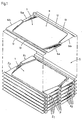
- FIG. 1 The embodiment of a plate heat exchanger shown schematically in FIG. 1 shows in perspective a plate stack S composed of a plurality of shaped individual plates 1, which are each connected to one another to form a plate pair P.
- Each individual plate 1 comprises a floor 11 which lies in a different plane than the longitudinal edges 12.
- each individual plate 1 is each with a Contact surface 13 formed, which is offset in height from the longitudinal edges 12.
- the offset between the contact surface 13 and the associated longitudinal edge 12 is twice as large as the offset between the longitudinal edges 12 and the bottom 11.
- the bottom 11 is therefore located in the middle between the plane of the longitudinal edges 12 and the plane of the contact surfaces 13.
- transverse edges 14a and 14b are diagonally opposite one another.
- FIG. 1 Two of the individual plates 1 shown as the uppermost part in FIG. 1 are connected to plate pairs P according to the lower representation in FIG. 1.
- Fig. 1 five complete plate pairs P are shown, with a single plate 1 being arranged on the top pair of plates, which is also connected to the top single plate 1 shown at a distance to form a plate pair P.
- the plate pairs P are connected in the area of the contact surfaces 13 to form the plate stack S, superimposed channels result for the two media participating in the heat exchange. While one medium flows in the flow channels, which are each formed by the plate pairs P, the other medium flows in the flow channels, which result from the joining of the plate pairs P to the plate stack S.
- the transverse edges lying in the plane of the longitudinal edges 12 14a of the individual plates 1 here form the inflow cross section Z 1 or the outflow cross section A 1 of the flow channels for the medium flowing between the plate pairs P.
- Fig. 1 which shows a counterflow heat exchanger, shows that due to the diagonal arrangement of the inlet and outlet openings, the inflow cross sections Z1 and Z2 for one medium next to the outflow cross sections A2 and A1 for the other medium, respectively offset by half a height of a pair of plates P.
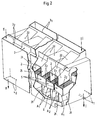
- the plate heat exchanger shown in perspective in FIG. 2 has two media I and II flowing through it in direct current, medium I being, for example, the heat-emitting medium and medium II the heat-absorbing medium.
- medium I being, for example, the heat-emitting medium and medium II the heat-absorbing medium.
- the heat exchange between the two media I and II takes place in plate stacks S which, according to FIG. 1, are formed from individual plates combined into plate pairs.
- These plate stacks S are arranged directly next to one another in such a way that their inflow cross sections Z 1, Z 2 are perpendicularly above the outflow cross sections A 1, A 2, as the section in FIG. 2 clearly shows.
- the inflow and outflow cross-sections belonging to one of the two media I or II are diagonally offset from one another, as can again be seen in FIG. 1.
- the inflow and outflow cross sections Z1, Z2 and A1, A2 of each plate stack S are separated from each other by a central wall 21 which extends over the entire length of the plate stack S.
- the middle walls 21 of adjacent plate stacks S are each connected to a common collecting duct 2 by a ceiling wall 22.
- these collecting channels 2 represent a supply or discharge of the medium I or II to or from respectively adjacent two plate stacks S.
- This inflow nozzle 3 1 is connected to those collecting channels 2 which open above the inflow cross sections Z 1 of the plate stack S.
- the streams of the medium I divide and get into the collecting channels 2 formed below the plate stack S, which lead the medium I to the outflow nozzle 4 1, which is arranged in the embodiment according to FIG. 2 below the inflow nozzle 3 1.
- the heat-absorbing medium II enters the inflow nozzle 32 from above and arrives from here into collecting channels 2, which lead to the inflow cross sections Z2 of the plate stack S.
- the partial flows of the medium 2 are divided in the plate stacks S and arrive in collecting channels 2, which in turn lead to an outflow nozzle 42, which is formed vertically below the inflow nozzle 32.
- the top walls 22 of the collecting channels 2 are designed to run obliquely, as can clearly be seen in the upper part of FIG. 2.
- the in the embodiment 2 realized DC circuit of the two media I and II participating in the heat exchange enables the generation of a surface temperature on the individual plates, which avoids the caking of solids when the media I and II enter the plate stack S as well as falling below the dew point. Should deposit products of the media arise, they can be collected and discharged via the collecting channels 2 and the outlet connections 4 1 and 4 2 below.
- the plate heat exchanger shown in Fig. 2 is accordingly particularly well suited for a recuperative heat exchange in connection with flue gas cleaning systems.
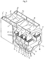
- the plate heat exchanger in Fig. 3 is designed as a countercurrent heat exchanger, in which the heat-emitting medium I according to the dash-dotted arrows from above enters the inflow nozzle 3 1 and from this inflow nozzle 3 1 into the collecting channels 2 connected to it.
- the heat-emitting medium I also divides in this case and emerges from the mutually spaced outflow cross sections A 1 of the plate stack S, namely in the underlying collection channels 2, which in turn are connected to the outflow nozzle 4 1 lying on the opposite side.
- the heat-absorbing medium II enters the inflow nozzle 32 from below and passes through the corresponding collecting channels 2 to the inflow cross sections Z 2 lying on the underside of the plate stack S. After heating the medium II in the plate stacks S, it emerges from the outflow cross sections A2; it passes into the collecting channels 2 above these outflow cross-sections A2, which are connected to the outflow connection 42.
- the inflow and outflow of the heat-absorbing medium II is indicated in Fig. 3 by solid arrows.
- both plate heat exchangers in FIGS. 2 and 3 show that despite a very compact and space-saving design, there is good access to the plate stacks S, which not only facilitates the installation of cleaning devices that may become necessary, but also good access to repairs or Maintenance work enabled.
- both representations show that the flow guidance of the two media I and II takes place in the shortest possible way and without any deflections causing pressure loss, so that the plate heat exchangers described, despite their compactness, are highly efficient.
Landscapes
- Engineering & Computer Science (AREA)
- Physics & Mathematics (AREA)
- Thermal Sciences (AREA)
- Mechanical Engineering (AREA)
- General Engineering & Computer Science (AREA)
- Heat-Exchange Devices With Radiators And Conduit Assemblies (AREA)
- Separation By Low-Temperature Treatments (AREA)
- Fuel Cell (AREA)
Applications Claiming Priority (2)
| Application Number | Priority Date | Filing Date | Title |
|---|---|---|---|
| DE9115813U DE9115813U1 (de) | 1991-12-20 | 1991-12-20 | Plattenwärmetauscher |
| DE9115813U | 1991-12-20 |
Publications (2)
| Publication Number | Publication Date |
|---|---|
| EP0548604A1 true EP0548604A1 (fr) | 1993-06-30 |
| EP0548604B1 EP0548604B1 (fr) | 1994-09-28 |
Family
ID=6874438
Family Applications (1)
| Application Number | Title | Priority Date | Filing Date |
|---|---|---|---|
| EP92120520A Expired - Lifetime EP0548604B1 (fr) | 1991-12-20 | 1992-12-02 | Echangeur de chaleur à plaques |
Country Status (7)
| Country | Link |
|---|---|
| US (1) | US5271459A (fr) |
| EP (1) | EP0548604B1 (fr) |
| AT (1) | ATE112385T1 (fr) |
| DE (2) | DE9115813U1 (fr) |
| DK (1) | DK0548604T3 (fr) |
| ES (1) | ES2065120T3 (fr) |
| RU (1) | RU2076295C1 (fr) |
Cited By (4)
| Publication number | Priority date | Publication date | Assignee | Title |
|---|---|---|---|---|
| NL1000706C2 (nl) * | 1995-06-30 | 1996-12-31 | Level Energietech Bv | Warmtewisselaar met verbeterde configuratie. |
| EP1738819A1 (fr) | 2005-06-17 | 2007-01-03 | GEA Ecoflex GmbH | Dispositif pour la purification catalytique de gaz d'échappement |
| KR20070045107A (ko) * | 2005-10-26 | 2007-05-02 | 레벨 홀딩 비.브이. | 열 교환기를 제조하기 위한 장치 및 방법 |
| WO2015152725A1 (fr) * | 2014-04-02 | 2015-10-08 | Level Holding B.V. | Récupérateur dont les canaux d'échange thermique s'étendent transversalement au sens de l'écoulement principal |
Families Citing this family (17)
| Publication number | Priority date | Publication date | Assignee | Title |
|---|---|---|---|---|
| DE9115813U1 (de) * | 1991-12-20 | 1992-02-20 | Balcke-Dürr AG, 4030 Ratingen | Plattenwärmetauscher |
| NL9301439A (nl) * | 1993-08-19 | 1995-03-16 | Eleonoor Van Andel | Warmtewisselaar en werkwijze voor het vervaardigen daarvan. |
| US6082445A (en) * | 1995-02-22 | 2000-07-04 | Basf Corporation | Plate-type heat exchangers |
| US5660228A (en) * | 1995-12-12 | 1997-08-26 | Altech Energy | Modular air-to-air heat exchanger |
| US5823249A (en) * | 1997-09-03 | 1998-10-20 | Batchelder; John Samual | Manifold for controlling interdigitated counterstreaming fluid flows |
| RU2188374C1 (ru) * | 2000-11-30 | 2002-08-27 | Федеральное государственное унитарное предприятие Российского космического агентства "Опытное конструкторское бюро "Факел" | Способ изготовления пластинчатого теплообменника |
| RU2208753C1 (ru) * | 2001-11-02 | 2003-07-20 | Черных Владимир Григорьевич | Пластинчатый теплообменник |
| US6622519B1 (en) * | 2002-08-15 | 2003-09-23 | Velocys, Inc. | Process for cooling a product in a heat exchanger employing microchannels for the flow of refrigerant and product |
| US7014835B2 (en) * | 2002-08-15 | 2006-03-21 | Velocys, Inc. | Multi-stream microchannel device |
| US6969505B2 (en) * | 2002-08-15 | 2005-11-29 | Velocys, Inc. | Process for conducting an equilibrium limited chemical reaction in a single stage process channel |
| US6851171B2 (en) | 2002-11-27 | 2005-02-08 | Battelle Memorial Institute | Method of fabricating multi-channel devices and multi-channel devices therefrom |
| US20050133204A1 (en) * | 2003-12-17 | 2005-06-23 | Renewaire, Llc | Energy recovery ventilator |
| US8747805B2 (en) * | 2004-02-11 | 2014-06-10 | Velocys, Inc. | Process for conducting an equilibrium limited chemical reaction using microchannel technology |
| JP5145718B2 (ja) * | 2006-02-03 | 2013-02-20 | 株式会社デンソー | 熱交換器 |
| GB2450760A (en) * | 2007-07-06 | 2009-01-07 | Eltek Energy Ab | Plate stack for use in a heat exchanger |
| CN104006683A (zh) * | 2014-05-01 | 2014-08-27 | 铜陵钱谊化工设备有限责任公司 | 一种板式换热器 |
| WO2022007296A1 (fr) * | 2020-07-07 | 2022-01-13 | 山东贝诺冷却设备股份有限公司 | Dispositif de dissipation de vapeur et tour de refroidissement |
Citations (5)
| Publication number | Priority date | Publication date | Assignee | Title |
|---|---|---|---|---|
| US2620169A (en) * | 1948-06-23 | 1952-12-02 | English Electric Co Ltd | Plate type heat exchanger |
| FR95672E (fr) * | 1966-01-22 | 1971-04-16 | Snecma | Perfectionnements aux échangeurs a plaques. |
| DE3202578A1 (de) * | 1982-01-27 | 1983-08-04 | Karl-Heinz Dipl.-Ing. 6589 Brücken Kaup | Kreuzstrom-plattentauscher mit bypass zur reduzierung der luftleistung und der druckverluste je tauscherelement |
| DE4100940C1 (fr) * | 1991-01-15 | 1991-11-21 | Balcke-Duerr Ag, 4030 Ratingen, De | |
| DE9115813U1 (de) * | 1991-12-20 | 1992-02-20 | Balcke-Dürr AG, 4030 Ratingen | Plattenwärmetauscher |
Family Cites Families (9)
| Publication number | Priority date | Publication date | Assignee | Title |
|---|---|---|---|---|
| GB647699A (en) * | 1948-06-23 | 1950-12-20 | English Electric Co Ltd | Improvements in and relating to plate type heat exchangers |
| GB1395439A (en) * | 1973-06-28 | 1975-05-29 | Roca Radiadores | Boiler units and hollow heat exchange elements therefor |
| GB1468514A (en) * | 1974-06-07 | 1977-03-30 | Apv Co Ltd | Plate heat exchangers |
| US4042018A (en) * | 1975-09-29 | 1977-08-16 | Des Champs Laboratories Incorporated | Packaging for heat exchangers |
| DE2549053A1 (de) * | 1975-11-03 | 1977-05-18 | Kernforschungsanlage Juelich | Waermetauscher mit plattenfoermiger waermetauschermatrix fuer die waermeuebertragung zwischen drei medien |
| US4503908A (en) * | 1979-10-01 | 1985-03-12 | Rockwell International Corporation | Internally manifolded unibody plate for a plate/fin-type heat exchanger |
| US4314607A (en) * | 1979-11-14 | 1982-02-09 | Deschamps Laboratories, Inc. | Plate type heat exchanger |
| JPS56144394A (en) * | 1980-04-11 | 1981-11-10 | Toshiba Corp | Heat exchanger |
| DE3429491A1 (de) * | 1984-08-10 | 1986-02-20 | Gea Ahlborn Gmbh & Co Kg, 3203 Sarstedt | Freistrom-plattenwaermeaustauscher |
-
1991
- 1991-12-20 DE DE9115813U patent/DE9115813U1/de not_active Expired - Lifetime
-
1992
- 1992-12-02 AT AT92120520T patent/ATE112385T1/de active
- 1992-12-02 DE DE59200569T patent/DE59200569D1/de not_active Expired - Lifetime
- 1992-12-02 ES ES92120520T patent/ES2065120T3/es not_active Expired - Lifetime
- 1992-12-02 DK DK92120520.9T patent/DK0548604T3/da active
- 1992-12-02 EP EP92120520A patent/EP0548604B1/fr not_active Expired - Lifetime
- 1992-12-18 US US07/992,707 patent/US5271459A/en not_active Expired - Lifetime
- 1992-12-18 RU RU9292016225A patent/RU2076295C1/ru active
Patent Citations (5)
| Publication number | Priority date | Publication date | Assignee | Title |
|---|---|---|---|---|
| US2620169A (en) * | 1948-06-23 | 1952-12-02 | English Electric Co Ltd | Plate type heat exchanger |
| FR95672E (fr) * | 1966-01-22 | 1971-04-16 | Snecma | Perfectionnements aux échangeurs a plaques. |
| DE3202578A1 (de) * | 1982-01-27 | 1983-08-04 | Karl-Heinz Dipl.-Ing. 6589 Brücken Kaup | Kreuzstrom-plattentauscher mit bypass zur reduzierung der luftleistung und der druckverluste je tauscherelement |
| DE4100940C1 (fr) * | 1991-01-15 | 1991-11-21 | Balcke-Duerr Ag, 4030 Ratingen, De | |
| DE9115813U1 (de) * | 1991-12-20 | 1992-02-20 | Balcke-Dürr AG, 4030 Ratingen | Plattenwärmetauscher |
Cited By (7)
| Publication number | Priority date | Publication date | Assignee | Title |
|---|---|---|---|---|
| NL1000706C2 (nl) * | 1995-06-30 | 1996-12-31 | Level Energietech Bv | Warmtewisselaar met verbeterde configuratie. |
| WO1997002461A1 (fr) * | 1995-06-30 | 1997-01-23 | Level Energietechniek B.V. | Echangeur thermique a configuration amelioree |
| EP1738819A1 (fr) | 2005-06-17 | 2007-01-03 | GEA Ecoflex GmbH | Dispositif pour la purification catalytique de gaz d'échappement |
| US7736601B2 (en) | 2005-06-17 | 2010-06-15 | Bd Heat Recovery Inc. | Apparatus for catalytic cleaning of waste gases |
| KR20070045107A (ko) * | 2005-10-26 | 2007-05-02 | 레벨 홀딩 비.브이. | 열 교환기를 제조하기 위한 장치 및 방법 |
| WO2015152725A1 (fr) * | 2014-04-02 | 2015-10-08 | Level Holding B.V. | Récupérateur dont les canaux d'échange thermique s'étendent transversalement au sens de l'écoulement principal |
| NL2012548A (nl) * | 2014-04-02 | 2016-01-12 | Level Holding Bv | Recuperator, waarvan de warmtewisselkanalen zich dwars op de lengterichting van het huis uitstrekken. |
Also Published As
| Publication number | Publication date |
|---|---|
| DK0548604T3 (da) | 1995-01-09 |
| EP0548604B1 (fr) | 1994-09-28 |
| RU2076295C1 (ru) | 1997-03-27 |
| US5271459A (en) | 1993-12-21 |
| ES2065120T3 (es) | 1995-02-01 |
| ATE112385T1 (de) | 1994-10-15 |
| DE9115813U1 (de) | 1992-02-20 |
| DE59200569D1 (de) | 1994-11-03 |
Similar Documents
| Publication | Publication Date | Title |
|---|---|---|
| EP0548604B1 (fr) | Echangeur de chaleur à plaques | |
| EP0974804B1 (fr) | Echangeur de chaleur, en particulier échangeur de chaleur pour gaz d'échappement | |
| DD239655A5 (de) | Gas/fluessigkeit- oder gas/gas-waermeaustauscher | |
| EP2452149B1 (fr) | Échangeur de chaleur à plaques | |
| EP0521298A2 (fr) | Dispositif d'échange de chaleur pour séchoir par réfrigération dans les installations d'air comprimé et échangeur de chaleur à tubes et plaques pour cette application | |
| EP0192212A1 (fr) | Echangeur de chaleur en spirale | |
| WO2013120600A2 (fr) | Dispositif de refroidissement ou de récupération de chaleur | |
| DE3220774A1 (de) | Plattenverdampfer oder -kondensator | |
| EP0826941B1 (fr) | Bloc d'échange de chaleur tubulaire | |
| DE2952736C2 (fr) | ||
| EP0044561A2 (fr) | Echangeur de chaleur, particulièrement pour échange de chaleur entre fluides gazeux | |
| EP0340433B1 (fr) | Module de tunnel pour créer une enceinte propre en technique à flux laminaire | |
| EP1738819B1 (fr) | Dispositif pour la purification catalytique de gaz d'échappement | |
| EP1139055B1 (fr) | Echangeur de chaleur à multiples faisceaux de tubes | |
| EP2369287A2 (fr) | Echangeur thermique | |
| EP0177904A2 (fr) | Dispositif pour l'échange de chaleur entre deux gaz en flux croisé | |
| EP1085285B1 (fr) | Echangeur de chaleur à plaques et évaporateur | |
| DE102011112857A1 (de) | Wärmeaustauscher | |
| DE3212162C2 (de) | Etagenspannrahmen mit Wärmetauscher | |
| DE102015104959B4 (de) | Gegenstromplattenwärmeübertrager | |
| EP0364617B1 (fr) | Dispositif de dénitration des gaz d'échappement d'une centrale | |
| DE8704409U1 (de) | Gegenstromwärmetauscher | |
| DE202010009815U1 (de) | Plattenwärmetauscher | |
| EP0443440B1 (fr) | Canal pour purger les gaz de fumées d'une chaudière | |
| DE7835175U1 (de) | Element zur direkten und/oder indirekten waermeaustausch zwischen fluiden |
Legal Events
| Date | Code | Title | Description |
|---|---|---|---|
| PUAI | Public reference made under article 153(3) epc to a published international application that has entered the european phase |
Free format text: ORIGINAL CODE: 0009012 |
|
| 17P | Request for examination filed |
Effective date: 19930430 |
|
| AK | Designated contracting states |
Kind code of ref document: A1 Designated state(s): AT BE CH DE DK ES FR GB IT LI NL SE |
|
| 17Q | First examination report despatched |
Effective date: 19940308 |
|
| RAP1 | Party data changed (applicant data changed or rights of an application transferred) |
Owner name: BDAG BALCKE-DUERR AKTIENGESELLSCHAFT |
|
| GRAA | (expected) grant |
Free format text: ORIGINAL CODE: 0009210 |
|
| AK | Designated contracting states |
Kind code of ref document: B1 Designated state(s): AT BE CH DE DK ES FR GB IT LI NL SE |
|
| REF | Corresponds to: |
Ref document number: 112385 Country of ref document: AT Date of ref document: 19941015 Kind code of ref document: T |
|
| REF | Corresponds to: |
Ref document number: 59200569 Country of ref document: DE Date of ref document: 19941103 |
|
| GBT | Gb: translation of ep patent filed (gb section 77(6)(a)/1977) |
Effective date: 19941101 |
|
| ITF | It: translation for a ep patent filed | ||
| ET | Fr: translation filed | ||
| REG | Reference to a national code |
Ref country code: DK Ref legal event code: T3 |
|
| EAL | Se: european patent in force in sweden |
Ref document number: 92120520.9 |
|
| REG | Reference to a national code |
Ref country code: ES Ref legal event code: FG2A Ref document number: 2065120 Country of ref document: ES Kind code of ref document: T3 |
|
| PLBE | No opposition filed within time limit |
Free format text: ORIGINAL CODE: 0009261 |
|
| STAA | Information on the status of an ep patent application or granted ep patent |
Free format text: STATUS: NO OPPOSITION FILED WITHIN TIME LIMIT |
|
| 26N | No opposition filed | ||
| PGFP | Annual fee paid to national office [announced via postgrant information from national office to epo] |
Ref country code: BE Payment date: 19971222 Year of fee payment: 6 |
|
| PGFP | Annual fee paid to national office [announced via postgrant information from national office to epo] |
Ref country code: ES Payment date: 19981221 Year of fee payment: 7 |
|
| PGFP | Annual fee paid to national office [announced via postgrant information from national office to epo] |
Ref country code: SE Payment date: 19981222 Year of fee payment: 7 |
|
| PGFP | Annual fee paid to national office [announced via postgrant information from national office to epo] |
Ref country code: DK Payment date: 19981223 Year of fee payment: 7 |
|
| PG25 | Lapsed in a contracting state [announced via postgrant information from national office to epo] |
Ref country code: BE Free format text: LAPSE BECAUSE OF NON-PAYMENT OF DUE FEES Effective date: 19981231 |
|
| BERE | Be: lapsed |
Owner name: BALCKE-DURR A.G. BDAG Effective date: 19981231 |
|
| PG25 | Lapsed in a contracting state [announced via postgrant information from national office to epo] |
Ref country code: DK Free format text: LAPSE BECAUSE OF NON-PAYMENT OF DUE FEES Effective date: 19991202 |
|
| PG25 | Lapsed in a contracting state [announced via postgrant information from national office to epo] |
Ref country code: SE Free format text: LAPSE BECAUSE OF NON-PAYMENT OF DUE FEES Effective date: 19991203 |
|
| EUG | Se: european patent has lapsed |
Ref document number: 92120520.9 |
|
| PG25 | Lapsed in a contracting state [announced via postgrant information from national office to epo] |
Ref country code: ES Free format text: LAPSE BECAUSE OF NON-PAYMENT OF DUE FEES Effective date: 20001203 |
|
| REG | Reference to a national code |
Ref country code: DK Ref legal event code: EBP |
|
| REG | Reference to a national code |
Ref country code: GB Ref legal event code: IF02 |
|
| REG | Reference to a national code |
Ref country code: ES Ref legal event code: FD2A Effective date: 20010113 |
|
| REG | Reference to a national code |
Ref country code: CH Ref legal event code: PUE Owner name: GEA ECOFLEX GMBH Free format text: BDAG BALCKE-DUERR AKTIENGESELLSCHAFT#HOMBERGER STRASSE 2#D-40882 RATINGEN (DE) -TRANSFER TO- GEA ECOFLEX GMBH#VOSS-STRASSE 11/13#31157 SARSTEDT (DE) |
|
| NLS | Nl: assignments of ep-patents |
Owner name: BABCOCK BORSIG AG Owner name: GEA ECOFLEX GMBH |
|
| REG | Reference to a national code |
Ref country code: GB Ref legal event code: 732E |
|
| REG | Reference to a national code |
Ref country code: FR Ref legal event code: TP |
|
| REG | Reference to a national code |
Ref country code: CH Ref legal event code: PFA Owner name: GEA ECOFLEX GMBH Free format text: GEA ECOFLEX GMBH#VOSS-STRASSE 11/13#31157 SARSTEDT (DE) -TRANSFER TO- GEA ECOFLEX GMBH#VOSS-STRASSE 11/13#31157 SARSTEDT (DE) |
|
| PGFP | Annual fee paid to national office [announced via postgrant information from national office to epo] |
Ref country code: AT Payment date: 20101214 Year of fee payment: 19 |
|
| PGFP | Annual fee paid to national office [announced via postgrant information from national office to epo] |
Ref country code: GB Payment date: 20101221 Year of fee payment: 19 |
|
| PGFP | Annual fee paid to national office [announced via postgrant information from national office to epo] |
Ref country code: DE Payment date: 20101217 Year of fee payment: 19 |
|
| PGFP | Annual fee paid to national office [announced via postgrant information from national office to epo] |
Ref country code: CH Payment date: 20111227 Year of fee payment: 20 Ref country code: NL Payment date: 20111228 Year of fee payment: 20 Ref country code: FR Payment date: 20120105 Year of fee payment: 20 |
|
| PGFP | Annual fee paid to national office [announced via postgrant information from national office to epo] |
Ref country code: IT Payment date: 20111229 Year of fee payment: 20 |
|
| REG | Reference to a national code |
Ref country code: DE Ref legal event code: R071 Ref document number: 59200569 Country of ref document: DE |
|
| REG | Reference to a national code |
Ref country code: DE Ref legal event code: R071 Ref document number: 59200569 Country of ref document: DE |
|
| REG | Reference to a national code |
Ref country code: NL Ref legal event code: V4 Effective date: 20121202 |
|
| REG | Reference to a national code |
Ref country code: CH Ref legal event code: PL |
|
| REG | Reference to a national code |
Ref country code: GB Ref legal event code: PE20 Expiry date: 20121201 |
|
| REG | Reference to a national code |
Ref country code: AT Ref legal event code: MK07 Ref document number: 112385 Country of ref document: AT Kind code of ref document: T Effective date: 20121202 |
|
| PG25 | Lapsed in a contracting state [announced via postgrant information from national office to epo] |
Ref country code: GB Free format text: LAPSE BECAUSE OF EXPIRATION OF PROTECTION Effective date: 20121201 |