EP0548607B1 - Méthode et dispositif pour couper une bande de matériau pour la fabrication de pneus - Google Patents
Méthode et dispositif pour couper une bande de matériau pour la fabrication de pneus Download PDFInfo
- Publication number
- EP0548607B1 EP0548607B1 EP92120547A EP92120547A EP0548607B1 EP 0548607 B1 EP0548607 B1 EP 0548607B1 EP 92120547 A EP92120547 A EP 92120547A EP 92120547 A EP92120547 A EP 92120547A EP 0548607 B1 EP0548607 B1 EP 0548607B1
- Authority
- EP
- European Patent Office
- Prior art keywords
- web
- winding drum
- cutting
- conveying device
- tangentially
- Prior art date
- Legal status (The legal status is an assumption and is not a legal conclusion. Google has not performed a legal analysis and makes no representation as to the accuracy of the status listed.)
- Expired - Lifetime
Links
- 239000000463 material Substances 0.000 title claims abstract description 52
- 238000005520 cutting process Methods 0.000 title claims abstract description 43
- 238000000034 method Methods 0.000 title claims abstract description 12
- 238000004804 winding Methods 0.000 claims abstract description 37
- 239000004035 construction material Substances 0.000 claims 1
- 230000002093 peripheral effect Effects 0.000 abstract 1
- 230000008719 thickening Effects 0.000 description 2
- 239000000853 adhesive Substances 0.000 description 1
- 230000001070 adhesive effect Effects 0.000 description 1
- 239000000109 continuous material Substances 0.000 description 1
- 238000012432 intermediate storage Methods 0.000 description 1
- 238000004519 manufacturing process Methods 0.000 description 1
- 230000001360 synchronised effect Effects 0.000 description 1
- 239000002699 waste material Substances 0.000 description 1
Images
Classifications
-
- B—PERFORMING OPERATIONS; TRANSPORTING
- B29—WORKING OF PLASTICS; WORKING OF SUBSTANCES IN A PLASTIC STATE IN GENERAL
- B29D—PRODUCING PARTICULAR ARTICLES FROM PLASTICS OR FROM SUBSTANCES IN A PLASTIC STATE
- B29D30/00—Producing pneumatic or solid tyres or parts thereof
- B29D30/06—Pneumatic tyres or parts thereof (e.g. produced by casting, moulding, compression moulding, injection moulding, centrifugal casting)
- B29D30/08—Building tyres
- B29D30/20—Building tyres by the flat-tyre method, i.e. building on cylindrical drums
- B29D30/30—Applying the layers; Guiding or stretching the layers during application
- B29D30/3007—Applying the layers; Guiding or stretching the layers during application by feeding a sheet perpendicular to the drum axis and joining the ends to form an annular element
-
- B—PERFORMING OPERATIONS; TRANSPORTING
- B26—HAND CUTTING TOOLS; CUTTING; SEVERING
- B26D—CUTTING; DETAILS COMMON TO MACHINES FOR PERFORATING, PUNCHING, CUTTING-OUT, STAMPING-OUT OR SEVERING
- B26D7/00—Details of apparatus for cutting, cutting-out, stamping-out, punching, perforating, or severing by means other than cutting
- B26D7/08—Means for treating work or cutting member to facilitate cutting
- B26D7/086—Means for treating work or cutting member to facilitate cutting by vibrating, e.g. ultrasonically
-
- B—PERFORMING OPERATIONS; TRANSPORTING
- B26—HAND CUTTING TOOLS; CUTTING; SEVERING
- B26D—CUTTING; DETAILS COMMON TO MACHINES FOR PERFORATING, PUNCHING, CUTTING-OUT, STAMPING-OUT OR SEVERING
- B26D7/00—Details of apparatus for cutting, cutting-out, stamping-out, punching, perforating, or severing by means other than cutting
- B26D7/08—Means for treating work or cutting member to facilitate cutting
- B26D7/14—Means for treating work or cutting member to facilitate cutting by tensioning the work
Definitions
- the invention relates to a method for cutting a material web to length according to the preamble of patent claim 1.
- a device for cutting a material web in which the material web is applied tangentially to a winding drum via a feed device and wound there. After less than one revolution of the winding drum, the remainder of the web extends tangentially from the drum to the cutter, and the web is cut to length in this position. The end of the material web is then gripped from above and below by a fixing device and the material web is placed over the remaining length.
- EP-A-0 264 720 describes a winding bandage device for producing a winding bandage.
- the device contains a pressure roller which can be pivoted towards the winding drum, but cannot be moved on the circumference of the drum.
- the invention has for its object to provide a method for cutting a material web for inserts of pneumatic vehicle tires, in which a defined processing length is achieved from continuous material feed without cutting.
- a device for performing the method is characterized by the features of claim 5
- the advantage of the invention is that the defined short remaining length ensures a reproducible material overlap or composition without thickening.
- the invention is advantageously one automatic processing of material webs accessible, especially in the case of previously unmanageable materials.
- a device according to the invention can easily be integrated directly into a production line for tire assembly.
- the invention achieves an increase in quality, and it also contributes to more economical waste avoidance.
- the main idea of the invention is to tighten the material to be cut to the shortest possible remaining length and to apply it to a winding drum immediately after cutting.
- a pressure roller is brought as close as possible to the cutting bar on the circumference of the winding drum, so that there is only a very short material length between the cutting point and the pressure roller. It should be noted, however, that the material web is not pinched between the pressure roller and the cutting bar, so that even tensioning over the entire remaining length is guaranteed.
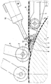
- the device has a winding drum 1, which can represent a tire building drum or an intermediate drum.
- the winding drum 1 is assigned a pressure roller 2, which is located on a swivel arm 3, the pivot point of which is movably arranged, so that the pressure roller 2 can be moved along the circumference of the winding drum 1.
- a feed device 4 with a feed belt 5 on which a material web 6 can be brought up tangentially to the winding drum 1.
- a cutting bar 7 with an exchangeable cutting bar 8 made of plastic between it and the winding drum 1.
- a vacuum device 9 is integrated in the cutting bar 7 and serves to fix the material web 6 in the area of the cutting point 10.
- the cutting bar 7 as well as the pressure roller 2 with its swivel arm 3 can be attached to the frame of the feed device 4.
- a conventional cutting system can also be provided for certain material webs 6. If the material web has a sufficiently high stickiness, the cutting knife 12 can also be set steeper, so that the cut surfaces and later contact surfaces at the joint become smaller.
- the feed device 4 as well as the cutting system 11 are designed such that they can be moved away from the winding drum 1 in order to ensure problem-free removal of wound material strips.
- the method according to the invention is explained in more detail below.
- a state is assumed in which the front end of the material strip 6 is at the cutting point 10 and the drum is stationary.
- the front end of the strip 6 is gripped by a device which is not designed, for example a vacuum device known per se, and is moved tangentially in the direction of the winding drum 1.
- the front end can then be detected, for example, by a vacuum nest in the winding drum 1 or, if there is already a strip of material on the winding drum 1, the front end holds the material web 6 due to the stickiness.
- the pressure roller 2 is then brought up to the winding drum 1 under defined pressure and the drum is set in rotation.
- the material web 6 is placed on it.
- the speeds of the feed belt 5 of the feed device 4 and the winding drum 1 can be synchronized with one another, but preferred for the winding drum 1 is a speed increased by approx is launched.
- the winding drum 1 When the winding drum 1 has almost covered a circumferential length, more precisely an angle of at least 330 °, preferably 340 to 350 °, it is stopped and at the same time the drive for the feed belt 5 is stopped.
- the front end of the material web 6 is located approximately at the level of the cutting bar 8.
- the vacuum device 9 is started so that the material web 6 is fixed in the region of the cutting point 10. If necessary, a conventional device can also be used for fixation in this area. Now the pressure roller 2 is moved toward the cutting bar 7 on the circumference of the winding drum, so that the material web 6 is tightened in the area between the cutting point 10 and the pressure roller 2.
- the pressure roller 2 essentially fulfills two functions. On the one hand, the part of the material web 6 that has already been placed on it introduced pre-tension fixed, on the other hand, the remaining length undergoes an even tightening, so that an extremely precise cut is achieved and after cutting the gap opens, so that the ends can not stick together again.
Landscapes
- Engineering & Computer Science (AREA)
- Mechanical Engineering (AREA)
- Life Sciences & Earth Sciences (AREA)
- Forests & Forestry (AREA)
- Tyre Moulding (AREA)
- Nonmetal Cutting Devices (AREA)
Claims (8)
- Procédé de coupe à la longueur d'une nappe continue (6) de matière de construction de bandages, destinée à des corsets de bandages pneumatiques de véhicules, par sectionnement transversal ou coupe en largeur au moyen d'un système de coupe, par exemple attaqué par ultra-sons la nappe continue (6) de matière étant amenée par un dispositif d'amenée (4) tangentiellement sur un tambour d'enroulement (1) et enroulée jusqu'à ce qu'à peu près une longueur correspondant à la circonférence soit atteinte et ensuite le tambour d'enroulement (1) est mis à l'arrêt,
caractérisé
en ce que la nappe continue (6) de matière est fixée dans la région d'un sommier de coupe (7) se trouvant immédiatement devant le dispositif d'amenée (4), en particulier par dépression, en ce qu'ensuite un rouleau de serrage (2) qui est en appui sous une pression définie contre la nappe continue (6) de matière lors de l'enroulement de cette dernière ou un rouleau séparé est rapproché du sommier de coupe (7) de manière qu'il déplace la nappe continue de matière (6) tangentiellement libre vers la circonférence du tambour d'enroulement, de sorte que la bande continue de matière (6) est mise sous tension et est fixée en un lieu aussi proche que possible du lieu de fixation produite par dépression et en ce que la bande continue de matière (6) qui est à cet état est sectionnée par une lame de coupe (12). - Procédé selon la revendication 1, caractérisé en ce que la vitesse adoptée du dispositif d'amenée (4) est d'environ 2% inférieure à la vitesse du tambour d'enroulement (1), de manière que la bande continue de matière (6) soit tenue sous précontrainte.
- Procédé selon la revendication 1, caractérisé en ce qu'après le sectionnement de la nappe continue de matière (6), le tambour d'enroulement (1) est remis en marche, de sorte que le rouleau de serrage (2) roule sur l'extrémité restante de la nappe continue de matière (6).
- Procédé selon la revendication 1, caractérisé en ce que la rotation du tambour d'enroulement (1) a lieu sur au moins 330° alors que le début de la nappe continue de matière (6) est à la première étape.
- Dispositif pour la mise en oeuvre du procédé selon la revendication 1, comprenant un tambour d'enroulement (1), un dispositif d'amenée (4) à l'aide duquel la nappe continue de matière (6) peut être amenée tangentiellement sur le tambour d'enroulement (1), un sommier de coupe (7) qui se trouve entre le tambour d'enroulement (1) et le dispositif d'amenée (4), caractérisé en ce qu'un système de coupe (11) déplaçable en direction transversale de la nappe continue de matière (6). par exemple attaqué par ultra-sons, est présent et en ce qu'un rouleau de serrage (2) destiné à entraîner la partie tangentiellement libre de la bande continue de matière (6) est réalisé de manière à être commandé en un lieu situé sur le tambour de commande (1) de manière à être placé à une distance aussi faible que possible du lieu de coupe (10).
- Dispositif selon la revendication 5, caractérisé en ce qu'un dispositif (9) d'exercice d'une dépression est intégré dans le sommier de coupe (7) pour la fixation de la nappe continue de matière (6).
- Dispositif selon la revendication 5, caractérisé en ce que le sommier de coupe (7) est fixé au dispositif d'amenée (4).
- Dispositif selon la revendication 5, caractérisé en ce que la lame (12) du dispositif de coupe (11) inscrit avec l'horizontale un angle compris entre 5 et 30°.
Applications Claiming Priority (2)
| Application Number | Priority Date | Filing Date | Title |
|---|---|---|---|
| DE4142723A DE4142723A1 (de) | 1991-12-21 | 1991-12-21 | Verfahren und vorrichtung zum ablaengen einer materialbahn aus reifenaufbaumaterial |
| DE4142723 | 1991-12-21 |
Publications (2)
| Publication Number | Publication Date |
|---|---|
| EP0548607A1 EP0548607A1 (fr) | 1993-06-30 |
| EP0548607B1 true EP0548607B1 (fr) | 1996-11-06 |
Family
ID=6447984
Family Applications (1)
| Application Number | Title | Priority Date | Filing Date |
|---|---|---|---|
| EP92120547A Expired - Lifetime EP0548607B1 (fr) | 1991-12-21 | 1992-12-02 | Méthode et dispositif pour couper une bande de matériau pour la fabrication de pneus |
Country Status (6)
| Country | Link |
|---|---|
| US (1) | US5273601A (fr) |
| EP (1) | EP0548607B1 (fr) |
| JP (1) | JP3187994B2 (fr) |
| AT (1) | ATE144941T1 (fr) |
| DE (2) | DE4142723A1 (fr) |
| ES (1) | ES2096012T3 (fr) |
Families Citing this family (28)
| Publication number | Priority date | Publication date | Assignee | Title |
|---|---|---|---|---|
| US6280548B1 (en) | 1995-01-05 | 2001-08-28 | Goodyear Tire & Rubber | Method and apparatus for building a laminate and forming a carcass subassembly for a tire |
| US5762740A (en) * | 1995-01-05 | 1998-06-09 | The Goodyear Tire & Rubber Company | Method for building a laminate from an assembly of tire components to form a casing |
| CA2145794A1 (fr) * | 1995-01-05 | 1996-07-06 | James Alfred Ii Benzing | Methode et appareil pour couper un stratifie d'elastomere renforce d'un cable |
| US5709760A (en) * | 1995-10-18 | 1998-01-20 | The Goodyear Tire & Rubber Company | Thin gauge, fine diameter steel cord reinforced tire ply fabric which is lap spliced |
| US6109322A (en) * | 1995-12-15 | 2000-08-29 | The Goodyear Tire & Rubber Company | Laminate composite structure for making an unvulcanized carcass for a radial ply tire as an intermediate article of manufacture |
| US6336488B1 (en) | 1995-12-15 | 2002-01-08 | The Goodyear Tire & Rubber Company | Unvulcanized noncord reinforced subassembly for incorporation in a tire casing |
| ES2189547B1 (es) * | 1998-12-17 | 2004-04-01 | Comercial De Tecnologia Sanitaria, S.A. | Maquina para el corte y soldadura de cinta continua de material plastico; en especial para cinturones de seguridad de vehiculos y similares. |
| US6592704B1 (en) | 1999-03-03 | 2003-07-15 | The Goodyear Tire & Rubber Company | Forming splice joints for elastomeric materials |
| US6755105B2 (en) | 2001-06-01 | 2004-06-29 | The Goodyear Tire & Rubber Company | Method and apparatus for cutting elastomeric materials and the article made by the method |
| US20060070504A1 (en) * | 2004-10-01 | 2006-04-06 | Downing Daniel R | Apparatus for cutting elastomeric materials |
| US7455002B2 (en) * | 2004-12-23 | 2008-11-25 | The Goodyear Tire & Rubber Company | Method for cutting elastomeric materials and the article made by the method |
| US7524398B2 (en) * | 2004-12-23 | 2009-04-28 | The Goodyear Tire & Rubber Company | Apparatus for making tire components, and a tire |
| US20060137814A1 (en) * | 2004-12-23 | 2006-06-29 | Downing Daniel R | Method for making reinforced elastomeric materials |
| US8561511B2 (en) * | 2004-12-23 | 2013-10-22 | The Goodyear Tire & Rubber Company | Anvil with vacuum width adjustment |
| US20060137804A1 (en) * | 2004-12-23 | 2006-06-29 | Downing Daniel R | Method for making tire ply |
| US20090145532A1 (en) * | 2005-07-15 | 2009-06-11 | Toyo Tire & Rubber Co., Ltd. | Method of Manufacturing A Carcass Ply |
| US7811399B2 (en) | 2006-09-21 | 2010-10-12 | The Goodyear Tire & Rubber Company | Tire component cutter apparatus and method of cutting |
| US7823490B2 (en) * | 2006-10-04 | 2010-11-02 | The Boeing Company | Cutting sequence for net trimming a composite layup at an oblique angle |
| DE102008056372A1 (de) * | 2008-10-27 | 2010-04-29 | Harburg-Freudenberger Maschinenbau Gmbh | Verfahren und Vorrichtung zum Schneiden |
| JP5366716B2 (ja) * | 2009-08-26 | 2013-12-11 | 株式会社ブリヂストン | 空気入りタイヤの製造方法 |
| KR101134639B1 (ko) * | 2009-12-21 | 2012-04-09 | 한국타이어 주식회사 | 타이어 성형드럼에 싱글비드를 부착하는 장치 |
| GB2482344A (en) * | 2010-07-30 | 2012-02-01 | Vestas Wind Sys As | Tapering an edge of a reinforcement sheet using an angled cutting tool |
| DE102012101766A1 (de) * | 2012-03-02 | 2013-09-05 | Continental Reifen Deutschland Gmbh | Verfahren zum Ablängen eines Reifenbauteiles aus einem Elastomer mit einer an den Seiten dünnen und spitz zulaufenden Materialdicke |
| FR2993197B1 (fr) * | 2012-07-11 | 2015-02-13 | Saint Gobain | Dispositif et procede de decoupe de matiere plastique en particulier d’un vitrage feuillete |
| JP6352166B2 (ja) * | 2014-12-03 | 2018-07-04 | 株式会社ブリヂストン | タイヤ構成部材の成形装置及び成形方法 |
| CN105034054B (zh) * | 2015-06-30 | 2016-08-24 | 重庆市金盾橡胶制品有限公司 | 能使得轮胎胎面切口吻合性好的新型胎面切割装置 |
| ITUB20153772A1 (it) * | 2015-09-21 | 2017-03-21 | Comerio Ercole Spa | Sistema automatico per il taglio trasversale di cord tessile e metallico gommato |
| TW202506495A (zh) * | 2023-07-27 | 2025-02-16 | 日商歐克包裝技術股份有限公司 | 薄片形成裝置及貼附裝置 |
Family Cites Families (9)
| Publication number | Priority date | Publication date | Assignee | Title |
|---|---|---|---|---|
| US3859152A (en) * | 1970-02-11 | 1975-01-07 | Firestone Tire & Rubber Co | Tire fabric cutter |
| DE2736401C2 (de) * | 1977-08-12 | 1985-02-07 | Continental Gummi-Werke Ag, 3000 Hannover | Vorrichtung zum Querschneiden von Warenbahnen aus biegsamen Stoffen |
| DE3249634C2 (de) * | 1981-08-31 | 1992-01-02 | Sumitomo Rubber Industries Ltd., Kobe, Hyogo | Verfahren und Vorrichtung um Aufbringen von Reifenmaterial auf eine Reifenaufbautrommel |
| JP2544117B2 (ja) * | 1986-10-23 | 1996-10-16 | 株式会社ブリヂストン | 細幅帯状体の供給装置 |
| US4813319A (en) * | 1987-04-01 | 1989-03-21 | The Firestone Tire & Rubber Company | Method and apparatus for transversely cutting strips of deformable material |
| JPH085141B2 (ja) * | 1987-04-14 | 1996-01-24 | 株式会社ブリヂストン | 帯状材料の貼付け装置 |
| NL8800077A (nl) * | 1988-01-14 | 1989-08-01 | Vmi Epe Holland | Inrichting voor het doorsnijden van een strook ongevulcaniseerde rubber. |
| JP2626903B2 (ja) * | 1988-05-10 | 1997-07-02 | 株式会社ブリヂストン | タイヤ構成部材の巻付け張力制御装置 |
| US5102490A (en) * | 1990-11-05 | 1992-04-07 | The Goodyear Tire & Rubber Company | Apparatus for applying tire sheet components |
-
1991
- 1991-12-21 DE DE4142723A patent/DE4142723A1/de not_active Withdrawn
-
1992
- 1992-12-02 EP EP92120547A patent/EP0548607B1/fr not_active Expired - Lifetime
- 1992-12-02 AT AT92120547T patent/ATE144941T1/de not_active IP Right Cessation
- 1992-12-02 ES ES92120547T patent/ES2096012T3/es not_active Expired - Lifetime
- 1992-12-02 DE DE59207492T patent/DE59207492D1/de not_active Expired - Lifetime
- 1992-12-09 JP JP32962892A patent/JP3187994B2/ja not_active Expired - Lifetime
- 1992-12-21 US US07/994,115 patent/US5273601A/en not_active Expired - Lifetime
Also Published As
| Publication number | Publication date |
|---|---|
| JPH05278148A (ja) | 1993-10-26 |
| JP3187994B2 (ja) | 2001-07-16 |
| EP0548607A1 (fr) | 1993-06-30 |
| DE4142723A1 (de) | 1993-07-01 |
| US5273601A (en) | 1993-12-28 |
| ES2096012T3 (es) | 1997-03-01 |
| ATE144941T1 (de) | 1996-11-15 |
| DE59207492D1 (de) | 1996-12-12 |
Similar Documents
| Publication | Publication Date | Title |
|---|---|---|
| EP0548607A1 (fr) | Méthode et dispositif pour couper une bande de matériau pour la fabrication de pneus | |
| DE69407820T2 (de) | Umroller zur herstellung von rollen aus bahnmaterial, wahlweise mit oder ohne wickelkern | |
| DE3784669T2 (de) | Vorrichtung zum befestigen einer ersatzbahn, die eine programmierte bewegung durchfuehrt, ohne eine solche bewegung zu unterbrechen. | |
| DE3232162A1 (de) | Vorrichtung zum aufbringen von reifenmaterial | |
| DE2038913C3 (de) | Vorrichtung zum Abschneiden streifenförmiger Abschnitte von einer Reifenverstärkungsbahn und zum Aufbringen der abgeschnittenen Abschnitte auf eine Reifenaufbautrommel | |
| DE2456342A1 (de) | Vorrichtung zum verbinden der stumpfen enden zweier aufeinanderfolgender baender | |
| DE3430739A1 (de) | Verfahren zum schneiden und ausstanzen sowie zufuehren von aufklebern verschiedener formen | |
| DE3109529A1 (de) | Vorrichtung zum verbinden des hinteren endes einer von einer auslaufenden rolle abgezogenen bahn mit dem vorderen ende einer von einer ersatzrolle abgezogenen bahn | |
| DE1906939A1 (de) | Verfahren und Vorrichtung zum Herstellen einer Stossverbindung zwischen den Enden zweier Kartonbahnen | |
| DE3918023C2 (de) | Verfahren und Vorrichtung zum automatischen Wickeln eines haftenden bandartigen Materials | |
| EP1524217A2 (fr) | Méthode pour le raccordement d'une bande | |
| DE69709388T2 (de) | Verfahren und vorrichtung zur herstellung von farbrollern | |
| EP0164709B1 (fr) | Procédé de fabrication d'ébauches de pneumatiques | |
| DE2256364C2 (de) | Klebegerät | |
| DE2259485A1 (de) | Vorrichtung zum verbinden von materialbahnen | |
| DE1511271A1 (de) | Verfahren und Vorrichtung zum Querdurchschneiden eines kontinuierlichen Papierstreifens,Films od.dgl. | |
| CH679488A5 (fr) | ||
| DE3119109A1 (de) | Vorrichtung und verfahren zum wechseln von vorratsrollen in einer etikettiermaschine | |
| EP2155482A1 (fr) | Procédé destiné à enrouler et épisser un profilé doté d'une âme destiné à un pneumatique de véhicule, au moyen d'un cylindre d'enroulement | |
| DE10351877B4 (de) | Schneidvorrichtung zum Abtrennen von Etiketten, Verfahren zum Abtrennen von Etiketten und Druckvorrichtung | |
| DE10112636B4 (de) | Verfahren und Vorrichtung zur Klebestellenvorbereitung einer Materialrolle | |
| DE19712524A1 (de) | Appliziervorrichtung sowie Applizierverfahren für Linerless-Etiketten | |
| DE3116744C2 (de) | Vorrichtung zum Quertrennen einer bewegten Folienbahn | |
| DE2629381A1 (de) | Verfahren zur herstellung eines tampons und vorrichtung zur durchfuehrung des verfahrens | |
| DE3136435A1 (de) | "raff- und schneidvorrichtung fuer verpackungsmaschinen" |
Legal Events
| Date | Code | Title | Description |
|---|---|---|---|
| PUAI | Public reference made under article 153(3) epc to a published international application that has entered the european phase |
Free format text: ORIGINAL CODE: 0009012 |
|
| AK | Designated contracting states |
Kind code of ref document: A1 Designated state(s): AT BE CH DE DK ES FR GB GR IT LI LU NL PT SE |
|
| 17P | Request for examination filed |
Effective date: 19930519 |
|
| 17Q | First examination report despatched |
Effective date: 19941025 |
|
| GRAG | Despatch of communication of intention to grant |
Free format text: ORIGINAL CODE: EPIDOS AGRA |
|
| GRAH | Despatch of communication of intention to grant a patent |
Free format text: ORIGINAL CODE: EPIDOS IGRA |
|
| GRAH | Despatch of communication of intention to grant a patent |
Free format text: ORIGINAL CODE: EPIDOS IGRA |
|
| GRAA | (expected) grant |
Free format text: ORIGINAL CODE: 0009210 |
|
| AK | Designated contracting states |
Kind code of ref document: B1 Designated state(s): AT BE CH DE DK ES FR GB GR IT LI LU NL PT SE |
|
| PG25 | Lapsed in a contracting state [announced via postgrant information from national office to epo] |
Ref country code: DK Effective date: 19961106 Ref country code: GR Free format text: LAPSE BECAUSE OF FAILURE TO SUBMIT A TRANSLATION OF THE DESCRIPTION OR TO PAY THE FEE WITHIN THE PRESCRIBED TIME-LIMIT Effective date: 19961106 |
|
| REF | Corresponds to: |
Ref document number: 144941 Country of ref document: AT Date of ref document: 19961115 Kind code of ref document: T |
|
| PG25 | Lapsed in a contracting state [announced via postgrant information from national office to epo] |
Ref country code: AT Effective date: 19961202 |
|
| REF | Corresponds to: |
Ref document number: 59207492 Country of ref document: DE Date of ref document: 19961212 |
|
| ITF | It: translation for a ep patent filed | ||
| REG | Reference to a national code |
Ref country code: CH Ref legal event code: NV Representative=s name: BOVARD AG PATENTANWAELTE |
|
| PG25 | Lapsed in a contracting state [announced via postgrant information from national office to epo] |
Ref country code: SE Effective date: 19970206 |
|
| ET | Fr: translation filed | ||
| GBT | Gb: translation of ep patent filed (gb section 77(6)(a)/1977) |
Effective date: 19970205 |
|
| REG | Reference to a national code |
Ref country code: ES Ref legal event code: FG2A Ref document number: 2096012 Country of ref document: ES Kind code of ref document: T3 |
|
| REG | Reference to a national code |
Ref country code: PT Ref legal event code: SC4A Free format text: AVAILABILITY OF NATIONAL TRANSLATION Effective date: 19961230 |
|
| PLBE | No opposition filed within time limit |
Free format text: ORIGINAL CODE: 0009261 |
|
| STAA | Information on the status of an ep patent application or granted ep patent |
Free format text: STATUS: NO OPPOSITION FILED WITHIN TIME LIMIT |
|
| 26N | No opposition filed | ||
| PGFP | Annual fee paid to national office [announced via postgrant information from national office to epo] |
Ref country code: CH Payment date: 20011120 Year of fee payment: 10 |
|
| PGFP | Annual fee paid to national office [announced via postgrant information from national office to epo] |
Ref country code: LU Payment date: 20011129 Year of fee payment: 10 |
|
| PGFP | Annual fee paid to national office [announced via postgrant information from national office to epo] |
Ref country code: BE Payment date: 20011220 Year of fee payment: 10 |
|
| REG | Reference to a national code |
Ref country code: GB Ref legal event code: IF02 |
|
| PG25 | Lapsed in a contracting state [announced via postgrant information from national office to epo] |
Ref country code: LU Free format text: LAPSE BECAUSE OF NON-PAYMENT OF DUE FEES Effective date: 20021202 |
|
| PG25 | Lapsed in a contracting state [announced via postgrant information from national office to epo] |
Ref country code: LI Free format text: LAPSE BECAUSE OF NON-PAYMENT OF DUE FEES Effective date: 20021231 Ref country code: CH Free format text: LAPSE BECAUSE OF NON-PAYMENT OF DUE FEES Effective date: 20021231 Ref country code: BE Free format text: LAPSE BECAUSE OF NON-PAYMENT OF DUE FEES Effective date: 20021231 |
|
| BERE | Be: lapsed |
Owner name: *CONTINENTAL A.G. Effective date: 20021231 |
|
| REG | Reference to a national code |
Ref country code: CH Ref legal event code: PL |
|
| PGFP | Annual fee paid to national office [announced via postgrant information from national office to epo] |
Ref country code: GB Payment date: 20041122 Year of fee payment: 13 Ref country code: PT Payment date: 20041122 Year of fee payment: 13 |
|
| PGFP | Annual fee paid to national office [announced via postgrant information from national office to epo] |
Ref country code: ES Payment date: 20041215 Year of fee payment: 13 |
|
| PG25 | Lapsed in a contracting state [announced via postgrant information from national office to epo] |
Ref country code: GB Free format text: LAPSE BECAUSE OF NON-PAYMENT OF DUE FEES Effective date: 20051202 |
|
| PG25 | Lapsed in a contracting state [announced via postgrant information from national office to epo] |
Ref country code: ES Free format text: LAPSE BECAUSE OF NON-PAYMENT OF DUE FEES Effective date: 20051203 |
|
| PG25 | Lapsed in a contracting state [announced via postgrant information from national office to epo] |
Ref country code: PT Free format text: LAPSE BECAUSE OF NON-PAYMENT OF DUE FEES Effective date: 20060602 |
|
| REG | Reference to a national code |
Ref country code: PT Ref legal event code: MM4A Effective date: 20060602 |
|
| GBPC | Gb: european patent ceased through non-payment of renewal fee |
Effective date: 20051202 |
|
| REG | Reference to a national code |
Ref country code: ES Ref legal event code: FD2A Effective date: 20051203 |
|
| PGFP | Annual fee paid to national office [announced via postgrant information from national office to epo] |
Ref country code: FR Payment date: 20110104 Year of fee payment: 19 |
|
| PGFP | Annual fee paid to national office [announced via postgrant information from national office to epo] |
Ref country code: NL Payment date: 20101213 Year of fee payment: 19 |
|
| REG | Reference to a national code |
Ref legal event code: SD Owner name: CONTINENTAL REIFEN DEUTSCHLAND GMBH Effective date: 20110318 Ref country code: NL |
|
| PGFP | Annual fee paid to national office [announced via postgrant information from national office to epo] |
Ref country code: IT Payment date: 20101229 Year of fee payment: 19 Ref country code: DE Payment date: 20101202 Year of fee payment: 19 |
|
| REG | Reference to a national code |
Ref country code: NL Ref legal event code: V1 Effective date: 20120701 |
|
| REG | Reference to a national code |
Ref country code: FR Ref legal event code: ST Effective date: 20120831 |
|
| REG | Reference to a national code |
Ref country code: DE Ref legal event code: R119 Ref document number: 59207492 Country of ref document: DE Effective date: 20120703 |
|
| PG25 | Lapsed in a contracting state [announced via postgrant information from national office to epo] |
Ref country code: DE Free format text: LAPSE BECAUSE OF NON-PAYMENT OF DUE FEES Effective date: 20120703 |
|
| PG25 | Lapsed in a contracting state [announced via postgrant information from national office to epo] |
Ref country code: IT Free format text: LAPSE BECAUSE OF NON-PAYMENT OF DUE FEES Effective date: 20111202 |
|
| PG25 | Lapsed in a contracting state [announced via postgrant information from national office to epo] |
Ref country code: NL Free format text: LAPSE BECAUSE OF NON-PAYMENT OF DUE FEES Effective date: 20120701 |
|
| PG25 | Lapsed in a contracting state [announced via postgrant information from national office to epo] |
Ref country code: FR Free format text: LAPSE BECAUSE OF NON-PAYMENT OF DUE FEES Effective date: 20120102 |