EP0548655A1 - Dispositif de chauffage - Google Patents
Dispositif de chauffage Download PDFInfo
- Publication number
- EP0548655A1 EP0548655A1 EP92120876A EP92120876A EP0548655A1 EP 0548655 A1 EP0548655 A1 EP 0548655A1 EP 92120876 A EP92120876 A EP 92120876A EP 92120876 A EP92120876 A EP 92120876A EP 0548655 A1 EP0548655 A1 EP 0548655A1
- Authority
- EP
- European Patent Office
- Prior art keywords
- burner
- temperature
- circuit
- threshold value
- heating device
- Prior art date
- Legal status (The legal status is an assumption and is not a legal conclusion. Google has not performed a legal analysis and makes no representation as to the accuracy of the status listed.)
- Granted
Links
- 238000010438 heat treatment Methods 0.000 title claims abstract description 16
- 239000000446 fuel Substances 0.000 claims abstract description 6
- 239000000463 material Substances 0.000 claims abstract description 6
- 238000002485 combustion reaction Methods 0.000 claims abstract description 5
- 238000011156 evaluation Methods 0.000 claims description 16
- 239000002912 waste gas Substances 0.000 abstract 3
- 238000000034 method Methods 0.000 abstract 1
- 239000007789 gas Substances 0.000 description 21
- 238000013459 approach Methods 0.000 description 2
- 241001156002 Anthonomus pomorum Species 0.000 description 1
- 238000010276 construction Methods 0.000 description 1
- 238000010586 diagram Methods 0.000 description 1
- 239000002737 fuel gas Substances 0.000 description 1
- 239000000203 mixture Substances 0.000 description 1
- 238000013021 overheating Methods 0.000 description 1
- XLYOFNOQVPJJNP-UHFFFAOYSA-N water Substances O XLYOFNOQVPJJNP-UHFFFAOYSA-N 0.000 description 1
Images

Classifications
-
- F—MECHANICAL ENGINEERING; LIGHTING; HEATING; WEAPONS; BLASTING
- F23—COMBUSTION APPARATUS; COMBUSTION PROCESSES
- F23N—REGULATING OR CONTROLLING COMBUSTION
- F23N5/00—Systems for controlling combustion
- F23N5/02—Systems for controlling combustion using devices responsive to thermal changes or to thermal expansion of a medium
- F23N5/022—Systems for controlling combustion using devices responsive to thermal changes or to thermal expansion of a medium using electronic means
-
- F—MECHANICAL ENGINEERING; LIGHTING; HEATING; WEAPONS; BLASTING
- F23—COMBUSTION APPARATUS; COMBUSTION PROCESSES
- F23N—REGULATING OR CONTROLLING COMBUSTION
- F23N5/00—Systems for controlling combustion
- F23N5/24—Preventing development of abnormal or undesired conditions, i.e. safety arrangements
- F23N5/242—Preventing development of abnormal or undesired conditions, i.e. safety arrangements using electronic means
-
- F—MECHANICAL ENGINEERING; LIGHTING; HEATING; WEAPONS; BLASTING
- F23—COMBUSTION APPARATUS; COMBUSTION PROCESSES
- F23N—REGULATING OR CONTROLLING COMBUSTION
- F23N2223/00—Signal processing; Details thereof
- F23N2223/08—Microprocessor; Microcomputer
-
- F—MECHANICAL ENGINEERING; LIGHTING; HEATING; WEAPONS; BLASTING
- F23—COMBUSTION APPARATUS; COMBUSTION PROCESSES
- F23N—REGULATING OR CONTROLLING COMBUSTION
- F23N2225/00—Measuring
- F23N2225/08—Measuring temperature
- F23N2225/10—Measuring temperature stack temperature
-
- F—MECHANICAL ENGINEERING; LIGHTING; HEATING; WEAPONS; BLASTING
- F23—COMBUSTION APPARATUS; COMBUSTION PROCESSES
- F23N—REGULATING OR CONTROLLING COMBUSTION
- F23N2225/00—Measuring
- F23N2225/08—Measuring temperature
- F23N2225/21—Measuring temperature outlet temperature
-
- F—MECHANICAL ENGINEERING; LIGHTING; HEATING; WEAPONS; BLASTING
- F23—COMBUSTION APPARATUS; COMBUSTION PROCESSES
- F23N—REGULATING OR CONTROLLING COMBUSTION
- F23N2233/00—Ventilators
- F23N2233/06—Ventilators at the air intake
-
- F—MECHANICAL ENGINEERING; LIGHTING; HEATING; WEAPONS; BLASTING
- F23—COMBUSTION APPARATUS; COMBUSTION PROCESSES
- F23N—REGULATING OR CONTROLLING COMBUSTION
- F23N2235/00—Valves, nozzles or pumps
- F23N2235/12—Fuel valves
- F23N2235/14—Fuel valves electromagnetically operated
-
- F—MECHANICAL ENGINEERING; LIGHTING; HEATING; WEAPONS; BLASTING
- F23—COMBUSTION APPARATUS; COMBUSTION PROCESSES
- F23N—REGULATING OR CONTROLLING COMBUSTION
- F23N2235/00—Valves, nozzles or pumps
- F23N2235/12—Fuel valves
- F23N2235/16—Fuel valves variable flow or proportional valves
-
- F—MECHANICAL ENGINEERING; LIGHTING; HEATING; WEAPONS; BLASTING
- F23—COMBUSTION APPARATUS; COMBUSTION PROCESSES
- F23N—REGULATING OR CONTROLLING COMBUSTION
- F23N2237/00—Controlling
- F23N2237/10—High or low fire
Definitions
- the invention relates to a heating device with a burner acting on a heat exchanger and an exhaust pipe made of a combustible or only temperature-resistant material, in the connection area of which is arranged a safety temperature limiter to a combustion chamber receiving the burner which, when a certain temperature is exceeded, supplies the fuel to the Brenners influencing signal emits.
- Exhaust systems or exhaust pipes for heating devices with low exhaust gas temperatures can be made entirely or partially of a flammable or only temperature-resistant material. It is only necessary to provide a safety temperature limiter that prevents the maximum permissible temperature of the exhaust pipe from being exceeded.
- the safety temperature limiter is formed by a capillary thermal switch which switches the burner off when a certain limit temperature is reached.
- the aim of the invention is to avoid these disadvantages and to propose a heating device of the type mentioned in the introduction, in which an exceeding of the respective limit value of the exhaust gas temperature is avoided.
- the safety temperature limiter is formed by a temperature sensor arranged in the exhaust gas line and an evaluation circuit processing its signals, which has a threshold value circuit which, when the threshold value is exceeded, causes the burner to be switched off and comprises a control circuit which, when approaching one predefined threshold value emits a signal influencing the burner's output control in the sense of reducing the same.
- the evaluation circuit comprises a selector switch for setting the threshold value of the threshold value circuit.
- the setting of the threshold switch can be very easily matched to the permissible temperatures used for the exhaust pipe, whereby the same components can always be used, regardless of the materials used for the exhaust pipe.
- the evaluation circuit has a microprocessor which also serves as a threshold circuit and to which the temperature sensor arranged in the exhaust gas line is connected on the input side via an analog-digital converter and an exhaust gas target value transmitter and on the output side with a fuel supply to the burner controlling solenoid valve is connected.
- a temperature sensor for detecting the flow temperature of a heating system and a flow setpoint generator are connected on the input side in each case via analog-digital converters, the microprocessor on the output side optionally with a blower assigned to the burner via a digital -Analog converter is connected.
- the heating device has a burner 2 which is arranged in a combustion chamber 1 and which is supplied with a fuel gas / air mixture via a blower 3 and a gas line 5 controlled by a solenoid valve 4.
- a heat exchanger 6 is arranged above the burner 2 and is connected to a radiator device (not shown) via a feed line 7 and a return line 8 in which a pump 9 is arranged.
- the air required for the blower 3 passes through an annular gap 11 surrounding an exhaust pipe 10 into the interior of the housing 12 and from there to the suction side of the blower 3.
- a temperature sensor 13 is arranged, which is connected to an evaluation circuit 14 via a connecting line 20. This is also connected to a sensor 16 which detects the temperature of the feed water via a line 17.
- the evaluation circuit 14 has a target exhaust gas value transmitter 15 for selecting a threshold value for the emission of a signal that prevents the fuel supply.
- the evaluation circuit controls the blower 3 via the line 18 in order to influence the load on the burner 3 and, via a line 19, the solenoid valve 4, which controls the gas supply to the burner 2.
- the evaluation circuit 14 has a microprocessor 21 which also serves as a threshold circuit and which, when the temperature value of the exhaust gas approaches the set threshold value, for example up to 10 ° C., has an output of the burner 2 reducing signal.
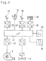
- the evaluation circuit 14 has a microprocessor 21 which is connected to the sensor 13 which detects the temperature of the exhaust gas via an analog-digital converter 22. Furthermore, an exhaust gas target value transmitter 15, a sensor 16 which detects the temperature of the flow of a heating system (not shown further) and a flow target value transmitter 25 are each connected on the input side to the microprocessor 21 via analog / digital converter 22. On the output side, the microprocessor 21 is connected via digital-analog converter 23 to the blower 3 of the burner 2 and the solenoid valve 4, which controls the gas supply to the burner. A display 26 and a voltage supply 24 are also connected to the microprocessor 21.
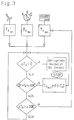
- the functional sequence of the evaluation circuit 14 is shown in FIG. 3.
- the actual exhaust gas temperature T Aist which is detected by the sensor 13, the set maximum value of the exhaust gas temperature T Amax and the target value for the flow temperature T Vsoll are processed as input variables .
- the instantaneous exhaust gas temperature T Aist is continuously compared with the set maximum exhaust gas temperature T Amax . If the difference between T Amax - T Aist is zero or negative, the maximum permissible exhaust gas temperature has been reached or exceeded. In this case, the burner 2 is locked.
- the target specification for the flow temperature T Vsoll is reduced according to a predetermined algorithm until the safety margin to the switch-off value is restored.
Landscapes
- Engineering & Computer Science (AREA)
- Chemical & Material Sciences (AREA)
- Combustion & Propulsion (AREA)
- Mechanical Engineering (AREA)
- General Engineering & Computer Science (AREA)
- Control Of Combustion (AREA)
- Yarns And Mechanical Finishing Of Yarns Or Ropes (AREA)
- Control And Other Processes For Unpacking Of Materials (AREA)
- Heat-Pump Type And Storage Water Heaters (AREA)
- Resistance Heating (AREA)
- Air-Conditioning For Vehicles (AREA)
Applications Claiming Priority (2)
| Application Number | Priority Date | Filing Date | Title |
|---|---|---|---|
| AT0246991A AT401569B (de) | 1991-12-12 | 1991-12-12 | Heizeinrichtung |
| AT2469/91 | 1991-12-12 |
Publications (2)
| Publication Number | Publication Date |
|---|---|
| EP0548655A1 true EP0548655A1 (fr) | 1993-06-30 |
| EP0548655B1 EP0548655B1 (fr) | 1997-05-14 |
Family
ID=3534921
Family Applications (1)
| Application Number | Title | Priority Date | Filing Date |
|---|---|---|---|
| EP92120876A Expired - Lifetime EP0548655B1 (fr) | 1991-12-12 | 1992-12-08 | Dispositif de chauffage |
Country Status (4)
| Country | Link |
|---|---|
| EP (1) | EP0548655B1 (fr) |
| AT (2) | AT401569B (fr) |
| DE (2) | DE4242382A1 (fr) |
| DK (1) | DK0548655T3 (fr) |
Cited By (4)
| Publication number | Priority date | Publication date | Assignee | Title |
|---|---|---|---|---|
| EP0664421A1 (fr) * | 1994-01-25 | 1995-07-26 | Emerson Electric Co. | Soupape de commande pour gaz |
| EP0892215A3 (fr) * | 1997-07-18 | 2000-07-12 | WEBASTO THERMOSYSTEME GmbH | Procédé de commande de la protection de surchauffe pour un appareil de chauffage |
| GB2358915A (en) * | 2000-02-02 | 2001-08-08 | Smiths Group Plc | Gas appliances and control systems |
| EP1130343A3 (fr) * | 2000-02-02 | 2003-01-22 | Vaillant GmbH | Installation de chauffage |
Families Citing this family (3)
| Publication number | Priority date | Publication date | Assignee | Title |
|---|---|---|---|---|
| DE4325414C2 (de) * | 1993-07-29 | 2000-02-17 | Daimler Chrysler Ag | Deformationssensor für eine Sicherheitseinrichtung zum Schutz von Fahrzeuginsassen bei einem Seitenaufprall |
| DE102021006085A1 (de) | 2021-12-09 | 2023-06-15 | Truma Gerätetechnik GmbH & Co. KG | Vorrichtung zum Erwärmen von Luft |
| NO20230257A1 (no) * | 2023-03-10 | 2024-05-27 | Safi Brannsikring As | System for tidlig detektering, varsling og forhindring av pipebrann |
Citations (4)
| Publication number | Priority date | Publication date | Assignee | Title |
|---|---|---|---|---|
| DE1027863B (de) * | 1955-12-07 | 1958-04-10 | Vaillant Joh Kg | Selbsttaetige Regelvorrichtung fuer Gas-Wasserheizer mit Waermetauscher |
| DE2500529A1 (de) * | 1974-01-10 | 1975-07-17 | Saunier Duval | Sicherheitsvorrichtung fuer gas- durchlauferhitzer mit geringer leistung |
| US4296727A (en) * | 1980-04-02 | 1981-10-27 | Micro-Burner Systems Corporation | Furnace monitoring system |
| FR2549204A1 (fr) * | 1983-07-13 | 1985-01-18 | Maillet Marcel | Generateur d'air souffle a temperature constante |
Family Cites Families (2)
| Publication number | Priority date | Publication date | Assignee | Title |
|---|---|---|---|---|
| FR2596501B1 (fr) * | 1986-03-28 | 1990-04-27 | Sdecc | Dispositif de securite pour chaudiere a gaz du type a ventilation mecanique controlee |
| JPS63254315A (ja) * | 1987-04-09 | 1988-10-21 | Matsushita Electric Ind Co Ltd | 温風暖房器の安全装置 |
-
1991
- 1991-12-12 AT AT0246991A patent/AT401569B/de not_active IP Right Cessation
-
1992
- 1992-12-08 DE DE4242382A patent/DE4242382A1/de not_active Withdrawn
- 1992-12-08 AT AT92120876T patent/ATE153122T1/de not_active IP Right Cessation
- 1992-12-08 EP EP92120876A patent/EP0548655B1/fr not_active Expired - Lifetime
- 1992-12-08 DE DE59208493T patent/DE59208493D1/de not_active Expired - Fee Related
- 1992-12-08 DK DK92120876.5T patent/DK0548655T3/da active
Patent Citations (4)
| Publication number | Priority date | Publication date | Assignee | Title |
|---|---|---|---|---|
| DE1027863B (de) * | 1955-12-07 | 1958-04-10 | Vaillant Joh Kg | Selbsttaetige Regelvorrichtung fuer Gas-Wasserheizer mit Waermetauscher |
| DE2500529A1 (de) * | 1974-01-10 | 1975-07-17 | Saunier Duval | Sicherheitsvorrichtung fuer gas- durchlauferhitzer mit geringer leistung |
| US4296727A (en) * | 1980-04-02 | 1981-10-27 | Micro-Burner Systems Corporation | Furnace monitoring system |
| FR2549204A1 (fr) * | 1983-07-13 | 1985-01-18 | Maillet Marcel | Generateur d'air souffle a temperature constante |
Non-Patent Citations (2)
| Title |
|---|
| PATENT ABSTRACTS OF JAPAN vol. 13, no. 462 (M-881)19. Oktober 1989 & JP-A-11 81 016 ( MATSUSHITA ELECTRIC ) 19. Juli 1989 * |
| PATENT ABSTRACTS OF JAPAN vol. 14, no. 221 (M-971)10. Mai 1990 & JP-A-20 52 917 ( HANADA YOSHIYUKI ) 22. Februar 1990 * |
Cited By (4)
| Publication number | Priority date | Publication date | Assignee | Title |
|---|---|---|---|---|
| EP0664421A1 (fr) * | 1994-01-25 | 1995-07-26 | Emerson Electric Co. | Soupape de commande pour gaz |
| EP0892215A3 (fr) * | 1997-07-18 | 2000-07-12 | WEBASTO THERMOSYSTEME GmbH | Procédé de commande de la protection de surchauffe pour un appareil de chauffage |
| GB2358915A (en) * | 2000-02-02 | 2001-08-08 | Smiths Group Plc | Gas appliances and control systems |
| EP1130343A3 (fr) * | 2000-02-02 | 2003-01-22 | Vaillant GmbH | Installation de chauffage |
Also Published As
| Publication number | Publication date |
|---|---|
| EP0548655B1 (fr) | 1997-05-14 |
| DK0548655T3 (da) | 1997-12-01 |
| DE4242382A1 (fr) | 1993-06-17 |
| DE59208493D1 (de) | 1997-06-19 |
| ATE153122T1 (de) | 1997-05-15 |
| AT401569B (de) | 1996-10-25 |
| ATA246991A (de) | 1996-02-15 |
Similar Documents
| Publication | Publication Date | Title |
|---|---|---|
| EP0392162B1 (fr) | Dispositif de cuisson à gaz comportant au moins un brûleur de rayonnement à gaz sous une plaque vitro-céramique et méthode pour réduire le temps de chauffage d'un tel dispositif de cuisson | |
| EP2594848B1 (fr) | Procédé de commande d'un appareil à combustion et appareil à combustion | |
| DE3026190A1 (de) | Heizeinrichtung | |
| EP0484280B1 (fr) | Installation pour la purification de l'air chargé de polluants | |
| DE3639172C2 (fr) | ||
| EP0062855B1 (fr) | Dispositif de régulation pour un dispositif de chauffage à gaz pour eau ou air | |
| DE2700025A1 (de) | Steuerungs- und ueberwachungssystem fuer gasstrahlungsbrenner zur beheizung von glaskeramik-kochflaechen | |
| EP0548655A1 (fr) | Dispositif de chauffage | |
| AT396028B (de) | Verfahren zur regelung eines voll vormischenden flaechenbrenners | |
| DE2910294C2 (de) | Temperaturregler | |
| DE3020228A1 (de) | Brennstoffbeheizte waermequelle | |
| EP0567060A1 (fr) | Procédé pour commander un brûleur à gaz avec un ventilateur | |
| AT397851B (de) | Heizgerät | |
| AT400623B (de) | Steuerung für einen flüssiggasbrenner | |
| EP0062856A1 (fr) | Dispositif de régulation pour une chaudière à gaz d'une installation de chauffage à eau chaude | |
| DE3204656C2 (de) | Brennstoffbeheizte Wärmequelle | |
| DE3689309T2 (de) | Steuerung der Fluidtemperatur bei einer Warmwasserzentralheizungsanlage und für eine Zentralheizungsanlage geeignete Komponenten. | |
| DE19616901C2 (de) | Verfahren zum Betrieb einer Kohlenstaub-Ventilatormühle für einen kohlenstaubgefeuerten Dampfkessel | |
| EP0623785A1 (fr) | Dispositif de commande pour des brûleurs d'installations de chauffage | |
| DE19825047A1 (de) | Flächenbrenner | |
| WO2008043347A1 (fr) | Réglage d'une puissance de chauffage d'un appareil de chauffage | |
| EP0793064A2 (fr) | Appareil de chauffage et méthode pour régler un appareil de chauffage | |
| AT393411B (de) | Abgas-stroemungssicherung fuer einen heizkessel mit geblaesebrenner | |
| AT401570B (de) | Verfahren zur steuerung eines gas-gebläsebrenners | |
| AT401981B (de) | Verfahren zum betrieb eines netzteiles |
Legal Events
| Date | Code | Title | Description |
|---|---|---|---|
| PUAI | Public reference made under article 153(3) epc to a published international application that has entered the european phase |
Free format text: ORIGINAL CODE: 0009012 |
|
| AK | Designated contracting states |
Kind code of ref document: A1 Designated state(s): AT BE CH DE DK ES FR GB GR IE IT LI LU NL PT SE |
|
| 17P | Request for examination filed |
Effective date: 19931202 |
|
| 17Q | First examination report despatched |
Effective date: 19950309 |
|
| GRAG | Despatch of communication of intention to grant |
Free format text: ORIGINAL CODE: EPIDOS AGRA |
|
| GRAH | Despatch of communication of intention to grant a patent |
Free format text: ORIGINAL CODE: EPIDOS IGRA |
|
| RAP1 | Party data changed (applicant data changed or rights of an application transferred) |
Owner name: VAILLANT GMBH Owner name: VAILLANT B.V. Owner name: VAILLANT LTD. Owner name: VAILLANT GES.M.B.H Owner name: VAILLANT S.A.R.L Owner name: N.V. VAILLANT S.A. Owner name: JOH. VAILLANT GMBH U. CO. |
|
| GRAH | Despatch of communication of intention to grant a patent |
Free format text: ORIGINAL CODE: EPIDOS IGRA |
|
| GRAA | (expected) grant |
Free format text: ORIGINAL CODE: 0009210 |
|
| AK | Designated contracting states |
Kind code of ref document: B1 Designated state(s): AT BE CH DE DK ES FR GB GR IE IT LI LU NL PT SE |
|
| PG25 | Lapsed in a contracting state [announced via postgrant information from national office to epo] |
Ref country code: GR Free format text: LAPSE BECAUSE OF FAILURE TO SUBMIT A TRANSLATION OF THE DESCRIPTION OR TO PAY THE FEE WITHIN THE PRESCRIBED TIME-LIMIT Effective date: 19970514 Ref country code: ES Free format text: THE PATENT HAS BEEN ANNULLED BY A DECISION OF A NATIONAL AUTHORITY Effective date: 19970514 |
|
| REF | Corresponds to: |
Ref document number: 153122 Country of ref document: AT Date of ref document: 19970515 Kind code of ref document: T |
|
| REG | Reference to a national code |
Ref country code: CH Ref legal event code: EP |
|
| ITF | It: translation for a ep patent filed | ||
| REF | Corresponds to: |
Ref document number: 59208493 Country of ref document: DE Date of ref document: 19970619 |
|
| PG25 | Lapsed in a contracting state [announced via postgrant information from national office to epo] |
Ref country code: SE Effective date: 19970814 Ref country code: PT Effective date: 19970814 |
|
| GBT | Gb: translation of ep patent filed (gb section 77(6)(a)/1977) |
Effective date: 19970725 |
|
| ET | Fr: translation filed | ||
| REG | Reference to a national code |
Ref country code: DK Ref legal event code: T3 |
|
| PG25 | Lapsed in a contracting state [announced via postgrant information from national office to epo] |
Ref country code: LU Free format text: LAPSE BECAUSE OF NON-PAYMENT OF DUE FEES Effective date: 19971208 |
|
| PLBE | No opposition filed within time limit |
Free format text: ORIGINAL CODE: 0009261 |
|
| STAA | Information on the status of an ep patent application or granted ep patent |
Free format text: STATUS: NO OPPOSITION FILED WITHIN TIME LIMIT |
|
| PG25 | Lapsed in a contracting state [announced via postgrant information from national office to epo] |
Ref country code: IE Free format text: LAPSE BECAUSE OF NON-PAYMENT OF DUE FEES Effective date: 19980330 |
|
| REG | Reference to a national code |
Ref country code: IE Ref legal event code: FD4D Ref document number: 73888 Country of ref document: IE |
|
| 26N | No opposition filed | ||
| PGFP | Annual fee paid to national office [announced via postgrant information from national office to epo] |
Ref country code: DK Payment date: 19990907 Year of fee payment: 8 |
|
| PGFP | Annual fee paid to national office [announced via postgrant information from national office to epo] |
Ref country code: NL Payment date: 19990908 Year of fee payment: 8 Ref country code: GB Payment date: 19990908 Year of fee payment: 8 Ref country code: FR Payment date: 19990908 Year of fee payment: 8 |
|
| PGFP | Annual fee paid to national office [announced via postgrant information from national office to epo] |
Ref country code: AT Payment date: 19991110 Year of fee payment: 8 |
|
| PGFP | Annual fee paid to national office [announced via postgrant information from national office to epo] |
Ref country code: BE Payment date: 19991116 Year of fee payment: 8 |
|
| PGFP | Annual fee paid to national office [announced via postgrant information from national office to epo] |
Ref country code: DE Payment date: 19991214 Year of fee payment: 8 |
|
| PGFP | Annual fee paid to national office [announced via postgrant information from national office to epo] |
Ref country code: CH Payment date: 20000331 Year of fee payment: 8 |
|
| PG25 | Lapsed in a contracting state [announced via postgrant information from national office to epo] |
Ref country code: GB Free format text: LAPSE BECAUSE OF NON-PAYMENT OF DUE FEES Effective date: 20001208 Ref country code: DK Free format text: LAPSE BECAUSE OF NON-PAYMENT OF DUE FEES Effective date: 20001208 Ref country code: AT Free format text: LAPSE BECAUSE OF NON-PAYMENT OF DUE FEES Effective date: 20001208 |
|
| PG25 | Lapsed in a contracting state [announced via postgrant information from national office to epo] |
Ref country code: LI Free format text: LAPSE BECAUSE OF NON-PAYMENT OF DUE FEES Effective date: 20001231 Ref country code: CH Free format text: LAPSE BECAUSE OF NON-PAYMENT OF DUE FEES Effective date: 20001231 Ref country code: BE Free format text: LAPSE BECAUSE OF NON-PAYMENT OF DUE FEES Effective date: 20001231 |
|
| BERE | Be: lapsed |
Owner name: N.V. VAILLANT S.A. Effective date: 20001231 |
|
| PG25 | Lapsed in a contracting state [announced via postgrant information from national office to epo] |
Ref country code: NL Free format text: LAPSE BECAUSE OF NON-PAYMENT OF DUE FEES Effective date: 20010701 |
|
| GBPC | Gb: european patent ceased through non-payment of renewal fee |
Effective date: 20001208 |
|
| REG | Reference to a national code |
Ref country code: CH Ref legal event code: PL |
|
| PG25 | Lapsed in a contracting state [announced via postgrant information from national office to epo] |
Ref country code: FR Free format text: LAPSE BECAUSE OF NON-PAYMENT OF DUE FEES Effective date: 20010831 |
|
| NLV4 | Nl: lapsed or anulled due to non-payment of the annual fee |
Effective date: 20010701 |
|
| REG | Reference to a national code |
Ref country code: DK Ref legal event code: EBP |
|
| REG | Reference to a national code |
Ref country code: FR Ref legal event code: ST |
|
| PG25 | Lapsed in a contracting state [announced via postgrant information from national office to epo] |
Ref country code: DE Free format text: LAPSE BECAUSE OF NON-PAYMENT OF DUE FEES Effective date: 20011002 |
|
| PG25 | Lapsed in a contracting state [announced via postgrant information from national office to epo] |
Ref country code: IT Free format text: LAPSE BECAUSE OF NON-PAYMENT OF DUE FEES;WARNING: LAPSES OF ITALIAN PATENTS WITH EFFECTIVE DATE BEFORE 2007 MAY HAVE OCCURRED AT ANY TIME BEFORE 2007. THE CORRECT EFFECTIVE DATE MAY BE DIFFERENT FROM THE ONE RECORDED. Effective date: 20051208 |