EP0062856A1 - Dispositif de régulation pour une chaudière à gaz d'une installation de chauffage à eau chaude - Google Patents
Dispositif de régulation pour une chaudière à gaz d'une installation de chauffage à eau chaude Download PDFInfo
- Publication number
- EP0062856A1 EP0062856A1 EP82102804A EP82102804A EP0062856A1 EP 0062856 A1 EP0062856 A1 EP 0062856A1 EP 82102804 A EP82102804 A EP 82102804A EP 82102804 A EP82102804 A EP 82102804A EP 0062856 A1 EP0062856 A1 EP 0062856A1
- Authority
- EP
- European Patent Office
- Prior art keywords
- gas
- control
- regulator
- air
- control device
- Prior art date
- Legal status (The legal status is an assumption and is not a legal conclusion. Google has not performed a legal analysis and makes no representation as to the accuracy of the status listed.)
- Granted
Links
- XLYOFNOQVPJJNP-UHFFFAOYSA-N water Substances O XLYOFNOQVPJJNP-UHFFFAOYSA-N 0.000 title claims abstract description 15
- 238000010438 heat treatment Methods 0.000 title claims abstract description 11
- 238000009434 installation Methods 0.000 title abstract 2
- 239000007789 gas Substances 0.000 claims abstract description 52
- CURLTUGMZLYLDI-UHFFFAOYSA-N Carbon dioxide Chemical compound O=C=O CURLTUGMZLYLDI-UHFFFAOYSA-N 0.000 claims abstract description 8
- QVGXLLKOCUKJST-UHFFFAOYSA-N atomic oxygen Chemical compound [O] QVGXLLKOCUKJST-UHFFFAOYSA-N 0.000 claims abstract description 6
- 229910052760 oxygen Inorganic materials 0.000 claims abstract description 6
- 239000001301 oxygen Substances 0.000 claims abstract description 6
- 229910002092 carbon dioxide Inorganic materials 0.000 claims abstract description 4
- 239000001569 carbon dioxide Substances 0.000 claims abstract description 4
- 239000003546 flue gas Substances 0.000 claims description 10
- UGFAIRIUMAVXCW-UHFFFAOYSA-N Carbon monoxide Chemical compound [O+]#[C-] UGFAIRIUMAVXCW-UHFFFAOYSA-N 0.000 claims description 9
- 238000002485 combustion reaction Methods 0.000 claims description 9
- 239000008236 heating water Substances 0.000 claims description 6
- 230000000930 thermomechanical effect Effects 0.000 claims description 2
- 230000001105 regulatory effect Effects 0.000 description 4
- 239000012528 membrane Substances 0.000 description 3
- 238000001816 cooling Methods 0.000 description 2
- 241001156002 Anthonomus pomorum Species 0.000 description 1
- 206010053615 Thermal burn Diseases 0.000 description 1
- 238000009833 condensation Methods 0.000 description 1
- 230000005494 condensation Effects 0.000 description 1
- 230000001276 controlling effect Effects 0.000 description 1
- 230000001419 dependent effect Effects 0.000 description 1
- 230000005284 excitation Effects 0.000 description 1
- 239000002737 fuel gas Substances 0.000 description 1
- 238000005259 measurement Methods 0.000 description 1
Images

Classifications
-
- F—MECHANICAL ENGINEERING; LIGHTING; HEATING; WEAPONS; BLASTING
- F23—COMBUSTION APPARATUS; COMBUSTION PROCESSES
- F23N—REGULATING OR CONTROLLING COMBUSTION
- F23N5/00—Systems for controlling combustion
- F23N5/02—Systems for controlling combustion using devices responsive to thermal changes or to thermal expansion of a medium
- F23N5/025—Systems for controlling combustion using devices responsive to thermal changes or to thermal expansion of a medium using electrical or electromechanical means
-
- F—MECHANICAL ENGINEERING; LIGHTING; HEATING; WEAPONS; BLASTING
- F23—COMBUSTION APPARATUS; COMBUSTION PROCESSES
- F23N—REGULATING OR CONTROLLING COMBUSTION
- F23N2225/00—Measuring
- F23N2225/08—Measuring temperature
-
- F—MECHANICAL ENGINEERING; LIGHTING; HEATING; WEAPONS; BLASTING
- F23—COMBUSTION APPARATUS; COMBUSTION PROCESSES
- F23N—REGULATING OR CONTROLLING COMBUSTION
- F23N2233/00—Ventilators
- F23N2233/06—Ventilators at the air intake
-
- F—MECHANICAL ENGINEERING; LIGHTING; HEATING; WEAPONS; BLASTING
- F23—COMBUSTION APPARATUS; COMBUSTION PROCESSES
- F23N—REGULATING OR CONTROLLING COMBUSTION
- F23N2233/00—Ventilators
- F23N2233/06—Ventilators at the air intake
- F23N2233/08—Ventilators at the air intake with variable speed
-
- F—MECHANICAL ENGINEERING; LIGHTING; HEATING; WEAPONS; BLASTING
- F23—COMBUSTION APPARATUS; COMBUSTION PROCESSES
- F23N—REGULATING OR CONTROLLING COMBUSTION
- F23N2235/00—Valves, nozzles or pumps
- F23N2235/12—Fuel valves
- F23N2235/14—Fuel valves electromagnetically operated
-
- F—MECHANICAL ENGINEERING; LIGHTING; HEATING; WEAPONS; BLASTING
- F23—COMBUSTION APPARATUS; COMBUSTION PROCESSES
- F23N—REGULATING OR CONTROLLING COMBUSTION
- F23N2235/00—Valves, nozzles or pumps
- F23N2235/12—Fuel valves
- F23N2235/16—Fuel valves variable flow or proportional valves
-
- F—MECHANICAL ENGINEERING; LIGHTING; HEATING; WEAPONS; BLASTING
- F23—COMBUSTION APPARATUS; COMBUSTION PROCESSES
- F23N—REGULATING OR CONTROLLING COMBUSTION
- F23N2235/00—Valves, nozzles or pumps
- F23N2235/12—Fuel valves
- F23N2235/18—Groups of two or more valves
-
- F—MECHANICAL ENGINEERING; LIGHTING; HEATING; WEAPONS; BLASTING
- F23—COMBUSTION APPARATUS; COMBUSTION PROCESSES
- F23N—REGULATING OR CONTROLLING COMBUSTION
- F23N2235/00—Valves, nozzles or pumps
- F23N2235/12—Fuel valves
- F23N2235/20—Membrane valves
-
- F—MECHANICAL ENGINEERING; LIGHTING; HEATING; WEAPONS; BLASTING
- F23—COMBUSTION APPARATUS; COMBUSTION PROCESSES
- F23N—REGULATING OR CONTROLLING COMBUSTION
- F23N2235/00—Valves, nozzles or pumps
- F23N2235/12—Fuel valves
- F23N2235/24—Valve details
-
- F—MECHANICAL ENGINEERING; LIGHTING; HEATING; WEAPONS; BLASTING
- F23—COMBUSTION APPARATUS; COMBUSTION PROCESSES
- F23N—REGULATING OR CONTROLLING COMBUSTION
- F23N5/00—Systems for controlling combustion
- F23N5/003—Systems for controlling combustion using detectors sensitive to combustion gas properties
- F23N5/006—Systems for controlling combustion using detectors sensitive to combustion gas properties the detector being sensitive to oxygen
-
- F—MECHANICAL ENGINEERING; LIGHTING; HEATING; WEAPONS; BLASTING
- F23—COMBUSTION APPARATUS; COMBUSTION PROCESSES
- F23N—REGULATING OR CONTROLLING COMBUSTION
- F23N5/00—Systems for controlling combustion
- F23N5/18—Systems for controlling combustion using detectors sensitive to rate of flow of air or fuel
Definitions
- Hot water collective heating systems are often operated with a flow temperature that is controlled depending on the outside temperature, while the heat supply to the individual rooms is regulated by radiator valves provided there, which can be adjusted manually or by means of a thermostat, depending on the heat demand in the room concerned.
- a temperature controller for collective heating systems which controls a control valve located in the supply or return line and is connected on the input side to two temperature sensors, one of which is the temperature in the supply line and the other the temperature in the return line measures. The controller is designed so that a predetermined temperature difference is maintained between the flow and return.
- DE-OS 27 47 969 shows a control device of this type for a heating system with admixture control, in which the control device acts on a mixing valve in order to maintain a predetermined temperature difference between flow and return.
- a thermostatic radiator valve provided there opens a larger flow cross-section and thus increases the amount of water flowing through. As a result, the heating water flows through the radiator faster, cooling less and thus the return temperature rises. In order to maintain a predetermined temperature difference, more hot water is consequently supplied by the mixing valve and the flow temperature is increased.
- the demand-based control is carried out on the water side with the aid of a flow or mixing valve, while the burner and thus the temperature of the hot water is controlled depending on the outside temperature, but not on the actual heat demand in the rooms.
- the object of the invention is to control the burner itself as a function of the heat requirement and in this way to feed it only that amount of gas which is required to generate the required heat.
- This object is achieved by the invention characterized in claim 1.
- the temperature difference between the flow and return of the heating water to the consumer that is to say, for example, to the radiators of a collective heating system, serves as a parameter for the actual heat demand.
- the amount of gas supplied to the burner of the boiler is regulated.
- the combustion air volume supplied to the boiler is regulated at the same time.
- the gas control device controlling the gas supply has the structure known from the company publication D3H-29 HONEYWELL COMPACT VALVES V4600 / 8600, the servo pressure regulator provided there, which can be adjusted by hand, by means of a servo pressure regulator which can be adjusted in terms of its setpoint by means of an electromagnetic drive, in accordance with the older DE- OS 30 15 980 is replaced.
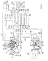
- a safety valve 4 and a main gas valve 5 are connected in series between inlet 2 and outlet 3.
- the safety valve 4 with switch-on pushbutton 6 and restart lock 7 is irrelevant to the mode of operation of the invention and is therefore not discussed in detail.
- the closing body 5 of the main gas valve is biased in the closing direction by a closing spring 8 and can be lifted off the valve seat 11 against the force of this closing spring 8 by means of a membrane 9 by the servo control pressure in the chamber 10.
- the control pressure for the chamber 10 is supplied via the channel 12 by a servo pressure regulator 13, the setpoint 5 of which can be adjusted by means of an electromagnetic drive 14.
- Room In one to be heated by the hot water heating system Room is the room thermostat 15, the contact of which closes as soon as the room temperature measured by its temperature sensor falls below the setpoint set on the room thermostat 15.
- the solenoid 16 of the gas control device 1 With the closing of this contact, the solenoid 16 of the gas control device 1 is connected to 'voltage, so that on the one hand it allows the input gas pressure to pass into the chamber 19 via the line 17 and a throttle point 18 and on the other hand with its closing body 20 the connection of this chamber to the channel 21 and blocked with this with the outlet 3. Consequently, a control pressure builds up in the chamber 19 which is dependent on the position of the throttle body 22 of the pressure regulator and which reaches the control chamber 10 of the diaphragm drive for the main gas valve 5, 11 via the channel 12 and lifts the closing body 5 from the seat 11. Thus, gas flows via line 23 to injector nozzle 24, which faces gas inlet 25 of burner 26.
- the gas stream sucks in primary air and also feeds it to the burner 26.
- the pilot burner 28 is connected to the gas control valve 1 via an ignition line 27. Its flame heats the thermocouple 29, which holds the safety valve 4 open via the magnet insert 30.
- a second injector nozzle 31 is provided, which faces a secondary air inlet 32 of the boiler 33.
- the secondary air inlet 32 opens into an air distributor pipe 35 provided with air outlet holes 34.
- the second injector nozzle 31 is connected via a line 36 to the outlet 37 of an air control valve .38, the inlet 39 of which is connected to a compressed air source in the form of a fan 40.
- the closing body 41 of the air control valve 38 is biased in the closing direction by a spring 42 and can be lifted off the seat 44 by a membrane 43 as soon as the pressure in the drive chamber 45 exceeds the forces exerted by the closing spring 42 and the pressure in the outlet 37 on the membrane 43.
- the control pressure in the chamber 45 also comes from the chamber 19 below the throttle body 22 of the servo pressure regulator 13 via a line 46. In this way, the gas supply and secondary air supply are regulated in the same direction by the servo pressure regulator 13.
- the sensor 47 of a flow switch 48 is located in the outlet 37 of the air control valve 38. Its normally open contact, which is closed by the air flow, is switched into the excitation circuit of the solenoid 16.
- the burner 26 heats a heat exchanger 51, which is connected to the radiators 53 via a circulation pump 52.
- the exhaust gases leave the boiler 33 through the flue gas exhaust 54, which passes into the chimney 56 via a draft interrupter 55.
- gas inlet 25 secondary air inlet 32 and flue gas outlet 54
- the housing 57 of the boiler 33 is closed on all sides.
- An air outlet nozzle 58 projects into the chimney 56 and is connected via a line 59 to the outlet 37 of the air control valve. With the help of this air outlet nozzle 58, an artificial draft is generated in the chimney 56.
- a throttle 60 the auxiliary air flow from the nozzle 58 can be adapted to the secondary air flow.
- a temperature sensor 63 is provided in the heating water supply line 62 from the heat exchanger 51 to the radiators 53 and a second temperature sensor 65 is provided in the return line 64.
- the outputs of both temperature sensors are connected to a controller 66, which is connected on the output side to the magnetic drive 14 of the servo pressure controller 13.
- the amount of gas supplied to the burner 26 is modulated as a function of the heat requirement. If the room temperature reaches the setpoint specified on the room thermostat 15, this interrupts the circuit of the switch-on solenoid valve, as a result of which the servo pressure regulator 13 no longer delivers control pressure into the diaphragm chamber 10 of the diaphragm drive for the main gas valve 5, 11, so that it closes under the influence of its closing spring 8. With the modulation and change in the gas supply to the main burner 26, the associated quantity of secondary air is continuously adapted to the gas throughput simultaneously via the control pressure line 46 and the air control valve 38. In this way, complete combustion and optimal utilization are achieved of the fuel gas.
- thermomechanical controller can also be used, as described for example in DE-PS 19 61 806 or DE-OS 27 47 969.
- the two temperature sensors 63 and 65 are shown as expansion sensors, which act hydraulically on an actuator via capillary tubes. This then directly mechanically adjusts the setpoint of the servo pressure regulator 13.
- the embodiment according to FIG. 2 differs from that according to FIG. 1 essentially by a changed control of the secondary air quantity depending on the gas throughput. While gas supply and secondary air supply are influenced in the same direction in the embodiment according to FIG. 1 with the help of the same servo pressure regulator 13, this acts in FIG. 2 only on the gas control valve and thus on the gas supply to the burner 26. At the same time, however, the amount of primary air drawn in via the injector nozzle 24 is changed in the same direction. To control the secondary air volume supplied and sucked in via the second injector nozzle 31, on the other hand, an oxygen or carbon dioxide sensor 70 is provided in the flue gas outlet 54, the output signal of which is fed to a controller 71.
- the controller 71 supplies an output signal to the magnetic drive 72 of the servo pressure controller 73 placed on the air control valve 38, whereby the setpoint of this pressure controller increases and at the same time the air control valve 41, 44 is opened further. Secondary air thus flows to the air distributor pipe 35, so that the excess air measured by the sensor 70 increases. If the excess air is too high, conversely, the amount of secondary air supplied via the air control valve 38 is throttled.
- the blower itself can also be controllable.
- the output line 74 of the controller 71 is connected via a connection 74 'directly to a blower control circuit, via which the speed and thus the performance of the blower can be influenced.
- the controllers 66 and 71 can be combined to form a common controller, possibly a digital controller using a microprocessor.
- a measurement of the CO 2 content of the flue gases can also be used to control the amount of secondary air.
- the circuit arrangement according to FIG. 2 works in the same way as previously described with reference to FIG. 1.
- the heating water consumer 53 itself serves as a measuring section for determining the amount of heat required.
- the greater the heat requirement the more the temperature difference between flow 62 and return 64 increases. Accordingly, the setpoint of the servo pressure controller 13 is adjusted via the guide controller 66 and the magnetic drive 14 and thus the gas throughput to the burner is controlled.
Landscapes
- Engineering & Computer Science (AREA)
- Chemical & Material Sciences (AREA)
- Combustion & Propulsion (AREA)
- Mechanical Engineering (AREA)
- General Engineering & Computer Science (AREA)
- Control Of Combustion (AREA)
Applications Claiming Priority (2)
| Application Number | Priority Date | Filing Date | Title |
|---|---|---|---|
| DE3114942 | 1981-04-13 | ||
| DE19813114942 DE3114942A1 (de) | 1981-04-13 | 1981-04-13 | Regeleinrichtung fuer den gasbefeuerten heizkessel einer warmwasser-heizungsanlage |
Publications (2)
| Publication Number | Publication Date |
|---|---|
| EP0062856A1 true EP0062856A1 (fr) | 1982-10-20 |
| EP0062856B1 EP0062856B1 (fr) | 1986-07-16 |
Family
ID=6130069
Family Applications (1)
| Application Number | Title | Priority Date | Filing Date |
|---|---|---|---|
| EP82102804A Expired EP0062856B1 (fr) | 1981-04-13 | 1982-04-02 | Dispositif de régulation pour une chaudière à gaz d'une installation de chauffage à eau chaude |
Country Status (2)
| Country | Link |
|---|---|
| EP (1) | EP0062856B1 (fr) |
| DE (2) | DE3114942A1 (fr) |
Cited By (6)
| Publication number | Priority date | Publication date | Assignee | Title |
|---|---|---|---|---|
| EP0229319A3 (en) * | 1985-12-16 | 1988-02-10 | Honeywell B.V. | Hot water heating installation with a heat consumption meter |
| US4785846A (en) * | 1986-12-24 | 1988-11-22 | Honeywell B.V. | Gas control apparatus with a pressure regulator |
| WO1993000559A1 (fr) * | 1991-06-29 | 1993-01-07 | Jin Min Choi | Systeme de chaudiere destinee a produire de l'eau chaude |
| US6003544A (en) * | 1996-04-02 | 1999-12-21 | Sit La Precisa S.R.L. | Valve unit for controlling the delivery pressure of a gas |
| US10100938B2 (en) | 2008-12-08 | 2018-10-16 | Robertshaw Controls Company | Variable flow gas valve and method for controlling same |
| CN113587140A (zh) * | 2021-08-09 | 2021-11-02 | 吉林同鑫热力集团股份有限公司 | 一种锅炉燃烧优化系统 |
Families Citing this family (1)
| Publication number | Priority date | Publication date | Assignee | Title |
|---|---|---|---|---|
| DE3742807A1 (de) * | 1987-12-17 | 1989-07-13 | Peter Huber | Temperiereinrichtung |
Citations (10)
| Publication number | Priority date | Publication date | Assignee | Title |
|---|---|---|---|---|
| US1604271A (en) * | 1924-12-17 | 1926-10-26 | Ferdinand J Friedman | Furnace equipment |
| GB918844A (en) * | 1958-11-13 | 1963-02-20 | Radiation Ltd | Improvements in or relating to temperature-controlled, gas-fired water heaters |
| US3960320A (en) * | 1975-04-30 | 1976-06-01 | Forney Engineering Company | Combustion optimizer |
| FR2324050A1 (fr) * | 1975-09-11 | 1977-04-08 | Bosch Gmbh Robert | Dispositif de reglage pour une installation de chauffage central a l'eau chaude |
| US4034911A (en) * | 1975-12-04 | 1977-07-12 | Emerson Electric Co. | Burner control system |
| FR2337316A1 (fr) * | 1975-12-29 | 1977-07-29 | Cidelcem | Generateur d'eau chaude a chauffage instantane |
| FR2356882A1 (fr) * | 1976-06-28 | 1978-01-27 | Claeys Flandria Nv | Perfectionnements aux procedes et dispositifs pour maintenir pratiquement constant a divers regimes de fonctionnement le rendement d'appareils a evacuation forcee comportant un dispositif de combustion |
| WO1980001603A1 (fr) * | 1979-01-31 | 1980-08-07 | Jydsk Varmekedelfab As | Methode et appareil de regulation de la combustion dans un four |
| EP0036613A1 (fr) * | 1980-03-20 | 1981-09-30 | Honeywell B.V. | Dispositif de régulation pour un échauffeur à eau ou air à combustion gazeuse pouvant être commandé par un capteur de température |
| GB2075718A (en) * | 1980-04-28 | 1981-11-18 | Hitachi Ltd | Method and apparatus for combustion control |
-
1981
- 1981-04-13 DE DE19813114942 patent/DE3114942A1/de not_active Withdrawn
-
1982
- 1982-04-02 EP EP82102804A patent/EP0062856B1/fr not_active Expired
- 1982-04-02 DE DE8282102804T patent/DE3271988D1/de not_active Expired
Patent Citations (10)
| Publication number | Priority date | Publication date | Assignee | Title |
|---|---|---|---|---|
| US1604271A (en) * | 1924-12-17 | 1926-10-26 | Ferdinand J Friedman | Furnace equipment |
| GB918844A (en) * | 1958-11-13 | 1963-02-20 | Radiation Ltd | Improvements in or relating to temperature-controlled, gas-fired water heaters |
| US3960320A (en) * | 1975-04-30 | 1976-06-01 | Forney Engineering Company | Combustion optimizer |
| FR2324050A1 (fr) * | 1975-09-11 | 1977-04-08 | Bosch Gmbh Robert | Dispositif de reglage pour une installation de chauffage central a l'eau chaude |
| US4034911A (en) * | 1975-12-04 | 1977-07-12 | Emerson Electric Co. | Burner control system |
| FR2337316A1 (fr) * | 1975-12-29 | 1977-07-29 | Cidelcem | Generateur d'eau chaude a chauffage instantane |
| FR2356882A1 (fr) * | 1976-06-28 | 1978-01-27 | Claeys Flandria Nv | Perfectionnements aux procedes et dispositifs pour maintenir pratiquement constant a divers regimes de fonctionnement le rendement d'appareils a evacuation forcee comportant un dispositif de combustion |
| WO1980001603A1 (fr) * | 1979-01-31 | 1980-08-07 | Jydsk Varmekedelfab As | Methode et appareil de regulation de la combustion dans un four |
| EP0036613A1 (fr) * | 1980-03-20 | 1981-09-30 | Honeywell B.V. | Dispositif de régulation pour un échauffeur à eau ou air à combustion gazeuse pouvant être commandé par un capteur de température |
| GB2075718A (en) * | 1980-04-28 | 1981-11-18 | Hitachi Ltd | Method and apparatus for combustion control |
Cited By (6)
| Publication number | Priority date | Publication date | Assignee | Title |
|---|---|---|---|---|
| EP0229319A3 (en) * | 1985-12-16 | 1988-02-10 | Honeywell B.V. | Hot water heating installation with a heat consumption meter |
| US4785846A (en) * | 1986-12-24 | 1988-11-22 | Honeywell B.V. | Gas control apparatus with a pressure regulator |
| WO1993000559A1 (fr) * | 1991-06-29 | 1993-01-07 | Jin Min Choi | Systeme de chaudiere destinee a produire de l'eau chaude |
| US6003544A (en) * | 1996-04-02 | 1999-12-21 | Sit La Precisa S.R.L. | Valve unit for controlling the delivery pressure of a gas |
| US10100938B2 (en) | 2008-12-08 | 2018-10-16 | Robertshaw Controls Company | Variable flow gas valve and method for controlling same |
| CN113587140A (zh) * | 2021-08-09 | 2021-11-02 | 吉林同鑫热力集团股份有限公司 | 一种锅炉燃烧优化系统 |
Also Published As
| Publication number | Publication date |
|---|---|
| DE3114942A1 (de) | 1982-10-28 |
| EP0062856B1 (fr) | 1986-07-16 |
| DE3271988D1 (en) | 1986-08-21 |
Similar Documents
| Publication | Publication Date | Title |
|---|---|---|
| EP0957314B1 (fr) | Dispositif de commande pour des brûleurs à gaz | |
| EP2594848B1 (fr) | Procédé de commande d'un appareil à combustion et appareil à combustion | |
| EP0062854B1 (fr) | Dispositif de chauffage à gaz pour eau ou air | |
| DE3026190A1 (de) | Heizeinrichtung | |
| EP0062855B1 (fr) | Dispositif de régulation pour un dispositif de chauffage à gaz pour eau ou air | |
| EP0275439B1 (fr) | Dispositif de régulation de puissance de générateurs de chaleur à carburant | |
| DE3911268A1 (de) | Regeleinrichtung fuer gasbrenner | |
| EP0062856A1 (fr) | Dispositif de régulation pour une chaudière à gaz d'une installation de chauffage à eau chaude | |
| EP0505714B1 (fr) | Dispositif de commande pour un brûleur de gaz avec un ventilateur pour l'alimentation d'air de combustion | |
| AT406903B (de) | Verfahren zum steuern des gasdurchsatzes | |
| EP0229319B1 (fr) | Installation de chauffage à eau chaude avec calorimètre | |
| EP0036613B1 (fr) | Dispositif de régulation pour un échauffeur à eau ou air à combustion gazeuse pouvant être commandé par un capteur de température | |
| DE3689309T2 (de) | Steuerung der Fluidtemperatur bei einer Warmwasserzentralheizungsanlage und für eine Zentralheizungsanlage geeignete Komponenten. | |
| EP0103303A2 (fr) | Source de chaleur chauffée au combustible | |
| DE3707883C1 (de) | Einrichtung zur Leistungsregelung von brennstoffbefeuerten Waermeerzeugern | |
| DE102004063992B4 (de) | Verfahren zur Steuerung einer Feuerungseinrichtung und Feuerungseinrichtung | |
| DE3333606A1 (de) | Brennstoffbeheizte waermequelle | |
| EP0158842B1 (fr) | Dispositif de régulation du rapport carburant/air d'une source de chaleur chauffée au carburant | |
| EP0036610B1 (fr) | Procédé de fonctionnement d'une source de chaleur chauffée par combustible | |
| DE3147857A1 (de) | Regeleinrichtung | |
| DE29808799U1 (de) | Regeleinrichtung für Gasbrenner | |
| EP0108349A2 (fr) | Source de chaleur chauffée au gaz | |
| DE1902063A1 (en) | Controlling oil or gas fired furnaces over - wide feed-ranges | |
| EP1260766B1 (fr) | Procédé d'adaptation d' un appareil de chauffage à brûleur à la cheminée d'air/fumée | |
| DE3044678A1 (de) | Regeleinrichtung fuer brenner |
Legal Events
| Date | Code | Title | Description |
|---|---|---|---|
| PUAI | Public reference made under article 153(3) epc to a published international application that has entered the european phase |
Free format text: ORIGINAL CODE: 0009012 |
|
| AK | Designated contracting states |
Designated state(s): BE DE FR GB IT NL |
|
| RHK1 | Main classification (correction) |
Ipc: F23N 5/02 |
|
| 17P | Request for examination filed |
Effective date: 19830122 |
|
| GRAA | (expected) grant |
Free format text: ORIGINAL CODE: 0009210 |
|
| AK | Designated contracting states |
Kind code of ref document: B1 Designated state(s): BE DE FR GB IT NL |
|
| REF | Corresponds to: |
Ref document number: 3271988 Country of ref document: DE Date of ref document: 19860821 |
|
| ET | Fr: translation filed | ||
| ITF | It: translation for a ep patent filed | ||
| PLBE | No opposition filed within time limit |
Free format text: ORIGINAL CODE: 0009261 |
|
| STAA | Information on the status of an ep patent application or granted ep patent |
Free format text: STATUS: NO OPPOSITION FILED WITHIN TIME LIMIT |
|
| 26N | No opposition filed | ||
| PGFP | Annual fee paid to national office [announced via postgrant information from national office to epo] |
Ref country code: FR Payment date: 19890307 Year of fee payment: 8 |
|
| PGFP | Annual fee paid to national office [announced via postgrant information from national office to epo] |
Ref country code: DE Payment date: 19890313 Year of fee payment: 8 |
|
| PGFP | Annual fee paid to national office [announced via postgrant information from national office to epo] |
Ref country code: GB Payment date: 19890331 Year of fee payment: 8 |
|
| PGFP | Annual fee paid to national office [announced via postgrant information from national office to epo] |
Ref country code: BE Payment date: 19890421 Year of fee payment: 8 |
|
| ITTA | It: last paid annual fee | ||
| PGFP | Annual fee paid to national office [announced via postgrant information from national office to epo] |
Ref country code: NL Payment date: 19890430 Year of fee payment: 8 |
|
| PG25 | Lapsed in a contracting state [announced via postgrant information from national office to epo] |
Ref country code: GB Effective date: 19900402 |
|
| PG25 | Lapsed in a contracting state [announced via postgrant information from national office to epo] |
Ref country code: BE Effective date: 19900430 |
|
| BERE | Be: lapsed |
Owner name: HONEYWELL B.V. Effective date: 19900430 |
|
| PG25 | Lapsed in a contracting state [announced via postgrant information from national office to epo] |
Ref country code: NL Effective date: 19901101 |
|
| GBPC | Gb: european patent ceased through non-payment of renewal fee | ||
| NLV4 | Nl: lapsed or anulled due to non-payment of the annual fee | ||
| PG25 | Lapsed in a contracting state [announced via postgrant information from national office to epo] |
Ref country code: FR Effective date: 19901228 |
|
| PG25 | Lapsed in a contracting state [announced via postgrant information from national office to epo] |
Ref country code: DE Effective date: 19910101 |
|
| REG | Reference to a national code |
Ref country code: FR Ref legal event code: ST |