EP0548666A1 - Vorrichtung für den Andruck beim Flachdruck und Verfahren zum Stabilisieren einer Offset-Flachdruckmaschine um ein genaues Farbbild zu drucken - Google Patents
Vorrichtung für den Andruck beim Flachdruck und Verfahren zum Stabilisieren einer Offset-Flachdruckmaschine um ein genaues Farbbild zu drucken Download PDFInfo
- Publication number
- EP0548666A1 EP0548666A1 EP92120935A EP92120935A EP0548666A1 EP 0548666 A1 EP0548666 A1 EP 0548666A1 EP 92120935 A EP92120935 A EP 92120935A EP 92120935 A EP92120935 A EP 92120935A EP 0548666 A1 EP0548666 A1 EP 0548666A1
- Authority
- EP
- European Patent Office
- Prior art keywords
- cylinder
- ink
- blanket
- ink removal
- removal cylinder
- Prior art date
- Legal status (The legal status is an assumption and is not a legal conclusion. Google has not performed a legal analysis and makes no representation as to the accuracy of the status listed.)
- Withdrawn
Links
- 238000007639 printing Methods 0.000 title claims abstract description 19
- 238000000034 method Methods 0.000 title claims abstract description 12
- 230000000087 stabilizing effect Effects 0.000 title description 3
- 239000000463 material Substances 0.000 claims description 15
- 239000002904 solvent Substances 0.000 claims description 12
- ZWEHNKRNPOVVGH-UHFFFAOYSA-N 2-Butanone Chemical group CCC(C)=O ZWEHNKRNPOVVGH-UHFFFAOYSA-N 0.000 claims description 6
- 238000013459 approach Methods 0.000 claims description 3
- 239000010985 leather Substances 0.000 claims description 2
- 239000002699 waste material Substances 0.000 abstract description 4
- 229910052751 metal Inorganic materials 0.000 description 8
- 239000002184 metal Substances 0.000 description 8
- 239000002609 medium Substances 0.000 description 7
- 238000001459 lithography Methods 0.000 description 4
- 238000009826 distribution Methods 0.000 description 3
- 238000004519 manufacturing process Methods 0.000 description 3
- 230000006641 stabilisation Effects 0.000 description 3
- 238000011105 stabilization Methods 0.000 description 3
- XLYOFNOQVPJJNP-UHFFFAOYSA-N water Substances O XLYOFNOQVPJJNP-UHFFFAOYSA-N 0.000 description 3
- 229920004943 Delrin® Polymers 0.000 description 2
- 229910052782 aluminium Inorganic materials 0.000 description 2
- XAGFODPZIPBFFR-UHFFFAOYSA-N aluminium Chemical compound [Al] XAGFODPZIPBFFR-UHFFFAOYSA-N 0.000 description 2
- 238000004140 cleaning Methods 0.000 description 2
- 238000007645 offset printing Methods 0.000 description 2
- 239000010935 stainless steel Substances 0.000 description 2
- 229910001220 stainless steel Inorganic materials 0.000 description 2
- VYZAMTAEIAYCRO-UHFFFAOYSA-N Chromium Chemical compound [Cr] VYZAMTAEIAYCRO-UHFFFAOYSA-N 0.000 description 1
- 229910000639 Spring steel Inorganic materials 0.000 description 1
- 229910000831 Steel Inorganic materials 0.000 description 1
- 230000009286 beneficial effect Effects 0.000 description 1
- 239000010960 cold rolled steel Substances 0.000 description 1
- 239000003086 colorant Substances 0.000 description 1
- 238000010276 construction Methods 0.000 description 1
- 230000000694 effects Effects 0.000 description 1
- 230000000977 initiatory effect Effects 0.000 description 1
- 238000012986 modification Methods 0.000 description 1
- 230000004048 modification Effects 0.000 description 1
- 239000010893 paper waste Substances 0.000 description 1
- 230000002093 peripheral effect Effects 0.000 description 1
- 229920000642 polymer Polymers 0.000 description 1
- 239000013587 production medium Substances 0.000 description 1
- 239000010959 steel Substances 0.000 description 1
Images


Classifications
-
- B—PERFORMING OPERATIONS; TRANSPORTING
- B41—PRINTING; LINING MACHINES; TYPEWRITERS; STAMPS
- B41F—PRINTING MACHINES OR PRESSES
- B41F35/00—Cleaning arrangements or devices
- B41F35/06—Cleaning arrangements or devices for offset cylinders
-
- B—PERFORMING OPERATIONS; TRANSPORTING
- B41—PRINTING; LINING MACHINES; TYPEWRITERS; STAMPS
- B41F—PRINTING MACHINES OR PRESSES
- B41F7/00—Rotary lithographic machines
- B41F7/18—Rotary lithographic machines specially adapted for proof printing
Definitions
- the invention relates generally to lithographic printing presses and more specifically to the initialization and stabilization of a production run on such presses.
- the offset lithographic process is used for printing various mediums, which may be in sheet or web form.
- the process is used in the metal can industry for printing product labels on sheets of steel, which typically run on the order of 30-40 inches square.
- Offset lithographic presses can be arranged two, three or more in a line so that multiple colors can be printed on a sheet or web during a single pass through a press line. In paper operations, 4-6 presses are common, while for metal decorating 2-3 presses are more typical. In order to print complex labels, the metal sheets frequently must be passed through the press line several times.
- the press when a new job is set up, the press must be adjusted and stabilized before it is ready to produce an accurate and acceptable image on the printed material. Specifically, adjustments are made to the press color and/or registration during start up, after which a certain amount of waste material must be run inasmuch as it takes time for the effect of the adjustments to carry through to the printed material. This period of time is generally referred to as the "run-in” period. Stabilization of the press during the run-in period is further complicated as sheets are passed through multiple presses in a press line.
- An offset lithographic press generally includes a combination of cylinders, usually a single plate cylinder, a blanket cylinder, and an impression cylinder, disposed in a parallel contacting arrangement.
- a press plate made of stainless steel, aluminum, or the like containing the image of art to be printed is mounted on each plate cylinder.
- an ink fountain along with ink distribution rollers supply ink to the surface of the press plate on the outer peripheral surface of the plate cylinder.
- offset lithography a similar arrangement provides water to the surface of the press plate.
- the printed material is fed through the nip between the blanket cylinder and the impression cylinder, which provides support for the medium to ensure accurate transfer of the ink image from the blanket.
- the invention includes a device and method for stabilizing an offset lithographic printing press to print a precise image on the surface of a material.
- the litho start-off device comprises an ink removal cylinder, the surface of which emulates the surface of the production sheets.
- the ink removal cylinder is disposed parallel to the blanket cylinder and mounted so that it can be selectively engaged and disengaged with a blanket disposed on the surface of the blanket cylinder.
- the ink removal cylinder is rotated with the same surface speed as the blanket. As the ink removal cylinder rotates while in contact with the blanket, the ink image is transferred from the surface of the blanket to the surface of the ink removal cylinder in the same manner as the ink is transferred to the production medium during actual operation.
- the litho start-off device further includes means for removing ink from the surface of the ink removal cylinder. Consequently, the ink removal cylinder can be engaged and continue to receive the ink image during an extensive run-in period, so that the press may be fully stabilized before beginning a commercial run.
- the litho start-off device during the run-in period can eliminate completely or at least substantially reduce the amount of start-up material required to stabilize the press at start-up or when adjustments are made to the press.
- the device according to the invention can greatly reduce the costs associated with start-up or press adjustments. While this reduction in the cost of printing can be beneficial to any offset lithographic printing press user, this savings can be substantial in the metal decorating industry.
- use of the device according to the invention can allow the press to be stabilized for a longer run-in period without greatly increasing the associated costs. Consequently, the press can be substantially stabilized so that it will provide higher print quality when beginning its commercial run.
- the invention may be realized in a method of preparing an offset printing press to print a stable ink image, an offset printing press which includes a litho start-off device, and a litho start-off device itself.
- the invention may be exhibited in a litho start-off device for use in an offset lithographic printing press to remove an image of ink from a circumferential surface of a rotating blanket cylinder during a run-in period during which the image and press are stabilized, the litho start-off device removing the ink image from the blanket cylinder before the ink image reaches a nip formed between the blanket cylinder and an impression cylinder, the litho start-off device comprising, in combination, an ink removal cylinder having a circumferential surface which receives the image, means for engaging and disengaging the ink removal cylinder with the blanket cylinder such that the surface of the ink removal cylinder contacts the surface of the blanket cylinder when engaged, means for driving the ink removal cylinder in synchronism with the blanket
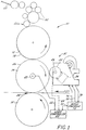
- Figure 1 is a schematic of an offset lithographic press constructed in accordance with the invention.
- FIG. 2 is an enlarged view of the litho start-off device shown in FIG. 1, partially broken away.
- FIG. 3 is a fragmentary view of a portion of the press shown in FIG. 1.
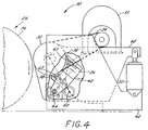
- FIG. 4 is another embodiment of the litho start-off device shown in FIG. 2.
- FIG. 1 an offset lithography printing press 10.
- the press 10 includes a plate cylinder 12, a blanket cylinder 14, and an impression cylinder 16, which are disposed in a parallel arrangement forming lines of contact between the adjacent rollers.
- One or more press plates 18, which contain the image of art that is to be printed on a material, are mounted along the outside circumference of the plate cylinder 12.
- the press plate 18 is generally made of stainless steel, aluminum, or the like.
- a printing blanket 24 is mounted on the blanket cylinder 14 for transfer of the final ink image to the printed medium.
- an ink fountain 20 and ink distribution rollers 22 are provided in order to supply ink to the surface of the image on the press plate 18.
- a similar arrangement (not shown) provides water to the surface of the press plate 18.
- ink from the ink fountain 20 is applied to the ink distribution rollers 22, which evenly distribute the ink before it is picked up by the press plate 18 of the plate cylinder 12 as it rotates against an ink form roller 22a.
- the ink image on the press plate 18 is then picked up by the blanket 24 as the blanket cylinder 14 rotates in synchronism with the plate cylinder 12.
- the ink then transfers from the blanket 24 to the surface of the medium to be printed (not shown) as it is fed through the nip 26 formed between the blanket cylinder 14 and the impression cylinder 16.
- the impression cylinder 16 provides support for the medium to insure accurate transfer of the ink image from the surface of the blanket 24 to the surface of the medium. It will further be appreciated that the medium may be fed through the nip 26 (in the direction generally indicated by the arrow 27) by any appropriate means.
- a litho start-off device 30 is mounted in the press adjacent to the blanket cylinder 14.
- the device 30 is only schematically illustrated in FIG. 1 and a general overview of the operation of the device 30 outlined in this paragraph, a more detailed description of the specific structure and operation of a preferred embodiment will follow.
- the device 30 includes an ink removal cylinder 32 that is rotatably mounted within the device 30, parallel to the blanket cylinder 14.
- the device 30 further includes means for moving the ink removal cylinder 32 into and out of engagement, so that the surface of the ink removal cylinder 32 contacts the blanket 24 along the circumferential surface of the blanket cylinder 14.
- the device 30 also includes means for driving the ink removal cylinder 32 in synchronism with the blanket cylinder 14, which is shown in detail in FIG. 2.
- the litho start-off device 30 also is provided with a scraper assembly 34.
- the scraper assembly 34 is disposed adjacent to the ink removal cylinder 32 and operates to continually remove the transferred ink image from the surface of the ink removal cylinder 32 as it rotates.
- FIG. 2 there is shown a more detailed view of the litho start-off device 30 of FIG. 1.
- the ink removal cylinder 32 is disposed in the litho start-off device 30 parallel to the blanket cylinder 14. It is an important feature of the invention that the surface of the ink removal cylinder 32 has a finish rough enough to strip the ink from the blanket 24, and yet smooth enough to be efficiently cleaned by the scraper assembly 34. In this way, the surface of the ink removal cylinder 32 will receive ink from the blanket cylinder 14 in a manner similar to that of conventional start-off material.
- the cylinder 32 is cold rolled steel tubing, chrome plated and ground to a 4 ⁇ finish.
- the scraper assembly 34 is provided to continually remove ink from the surface of the ink removal cylinder 32.
- the litho start-off device 30 shown in FIG. 2 is partially broken away to more clearly show the scraper assembly 34.
- the scraper assembly 34 includes two scrapers 36, 38, and a solvent wiper 40 disposed along the surface of the ink removal cylinder 32 between the scrapers 36, 38.
- scrapers are fabricated from the polymeric material, Delrin proved satisfactory.
- Leather backed with spring steel has also given good results.
- Other appropriate materials, such as other polymers, rubber, or the like may also be employed.
- a solvent such as methyl ethyl ketone may be utilized with a felt pad in the solvent wiper 40.
- the solvent may be sprayed or misted onto the surface of the ink removal cylinder 32 through one or more nozzles 41, as shown in another embodiment of the litho start-off device illustrated in FIG. 4.
- any cleaning means may be utilized that will adequately remove the ink from the surface of the ink removal cylinder 32, so long as the cylinder 32 is cleaned and is available for continuous removal of ink from the blanket 24.
- the surface of the ink removal cylinder 32 must be adequately smooth to allow removal of the ink by the ink scraper assembly 34, in this embodiment, the scrapers 36, 38 and wiper 40.
- the scrapers 36, 38 and the solvent wiper 40 are mounted on a bracket 42, which hinges about point 44. Additionally, the assembly may be adjusted to seat against the surface of the ink removal cylinder 32 with a desired amount of force to ensure complete removal of ink from the cylinder 32.
- a force of 500 pounds provided acceptable contact between the scrapers and the surface of the blanket cylinder.
- satisfactory results have likewise been achieved using a single blade acting like a squeegee with less than 500 lbs. being applied.
- the litho start-off device 30 is mounted within the press 10.
- the device 30 is mounted by way of a stationary bracket 46.
- a stationary bracket 46 may be provided at opposite end of the device 30 in order to secure it to the press 10.
- the device 30 is described as being mounted by a bracket 46 disposed at each end of the cylinder 32, one skilled in the art will appreciate that the device 30 may be mounted to the press 10 by any appropriate means that adequately secures the components therein.
- the ink removal cylinder 32 In order to provide a line of contact between the ink removal cylinder 32 and the blanket 24 for transfer of the ink image from one surface to the other, means are provided whereby the ink removal cylinder 32 may be moved into engagement with the blanket cylinder 14.
- the ink removal cylinder 32 is rotatably mounted to a bracket 48, which is pivotably mounted to stationary bracket 46. As with stationary bracket 46, it will be appreciated that a pivotable bracket 48 is provided at each end of the ink removal cylinder 32.
- an actuating cylinder 52 is provided between arms of the stationary bracket 46 and the pivotable bracket 48.
- the actuating cylinder may be powered either hydraulically, pneumatically, or mechanically to pivot bracket 48 to engage or disengage the ink removal cylinder 32 with the blanket cylinder 14.
- the actuating cylinder 52 is powered pneumatically. According to an important aspect of the invention, the contact force between the cylinders 32, 14 must be great enough to allow the image to transfer, but not so great that it distorts the image on the surface of the blanket 24.
- the engagement means has been described herein with reference to a pivotable unit, it will be appreciated that the ink removal cylinder 32 may be moved into engagement by an alternate means.
- the cylinder 32 may be moved into engagement in a linear fashion, by sliding the assembly into position.
- an appropriate driving means is provided.
- a servo motor 53 coupled to the ink removal cylinder 32 by means of a precision lug belt 54 drives the ink removal cylinder 32 at a desired speed.
- the surface speed of the ink removal cylinder 32 is precisely matched to the surface speed of the blanket 24. In this way, the ink image transfers between the cylinders 14, 32 without causing distortion of the image on the blanket 24. While this synchronization of the blanket cylinder 14 and the ink removal cylinder 32 may be accomplished by any appropriate means, electronic gearing is utilized in the preferred embodiment to obtain this synchronization.
- the axis of the ink removal cylinder 32 is programmed to track the axis of the blanket cylinder 14, or the master axis, at a specified ratio.
- the ratio of the blanket cylinder to the ink removal cylinder is on the order of 1 : 2.5
- the ink removal cylinder 32 must be engaged and disengaged from contact with the blanket cylinder 14 without disturbing the ink image on the blanket 24.
- the blanket cylinder 14 generally contains a clamping section 56 along its surface. It will be appreciated that the engagement and disengagement of the ink removal cylinder 32 at the precise moment when the cylinder 32 is adjacent to this clamping section will minimize any distortion in the ink image on the blanket 24 due to the movement of the litho start-off device 30.
- a logic controller 60 in order to control the timing of the engagement and disengagement process, as well as the speed of the ink removal cylinder, there is provided a logic controller 60 along with shaft encoders 62, 64, and various feedback devices.
- the shaft encoder 62 of the blanket cylinder 14 provides signals 66 to the logic controller 60 corresponding to the speed of the blanket cylinder 14, as well as the precise position of the blanket cylinder 14 and its clamping section 56 at any particular time.
- the shaft encoder 64 of the ink removal cylinder 32 provides a signal 68 that corresponds to the speed of the ink removal cylinder 32.
- the logic controller 60 utilizes the information from the signals 66, 68 to provide a signal 70 to the servo controls 72.
- the servo controls 72 in turn provide signals 74, 76 to the servo motor 53, which provides a feedback signal 78 to the servo controls 72.
- the information from the shaft encoders 62, 64 is utilized to control the operation of the litho start-off device 30 by controlling the speed and movement of the ink removal cylinder 32.
- the press In operation, when the press is first inked up or when adjustments are made to the setup of the press, the press is turned on.
- the shaft encoder 62 provides a signal 66 to logic controller 60 corresponding to the speed and position of the blanket cylinder 14.
- the logic controller in turn provides a signal 70 to the servo controls 72.
- the servo controls signal the servo motor 53 to rotate the ink removal cylinder 32 in synchronism with the blanket cylinder 14, and signal the logic controls of the actuating cylinder to engage the ink removal cylinder 32 with the blanket cylinder 14 as the clamping section 56 of the blanket cylinder 14 rotates past the litho start-off device 30.
- the feedback signal 78 from the motor 53 permits the servo controls 72 to continually adjust the speed of the ink removal cylinder 32 in order to precisely synchronize the speed with that of the blanket cylinder 14.
- ink is transferred from the blanket 24 to the surface of the ink removal cylinder 32.
- the scrapers 36, 38 and the solvent wiper 40 of the scraper assembly 34 remove the ink from the surface of the ink removal cylinder 32, so that the ink removal cylinder 32 continues to present to the blanket 24 a clean surface for receiving the ink image.
- the press can be operated for a sufficient length of time to allow true stabilization and consistency in image quality before the press begins a commercial run.
- the logic controller signals the sheet feeder (not shown) located at the front of the press line to start feeding sheets.
- the logic controller 60 then signals the servo controls 72 and the logic controls of the actuating cylinder 52 to disengage the litho start-off device 30 from the blanket cylinder 14 at the clamping section 56 at the moment when the first commercial sheet approaches the nip 26 between the blanket cylinder 14 and the impression cylinder 16.
Landscapes
- Engineering & Computer Science (AREA)
- Mechanical Engineering (AREA)
- Inking, Control Or Cleaning Of Printing Machines (AREA)
- Rotary Presses (AREA)
Applications Claiming Priority (2)
| Application Number | Priority Date | Filing Date | Title |
|---|---|---|---|
| US07/805,466 US5235913A (en) | 1991-12-10 | 1991-12-10 | Litho start-off device and method of stabilizing an offset lithographic printing press to print a precise ink image |
| US805466 | 1991-12-10 |
Publications (1)
| Publication Number | Publication Date |
|---|---|
| EP0548666A1 true EP0548666A1 (de) | 1993-06-30 |
Family
ID=25191637
Family Applications (1)
| Application Number | Title | Priority Date | Filing Date |
|---|---|---|---|
| EP92120935A Withdrawn EP0548666A1 (de) | 1991-12-10 | 1992-12-09 | Vorrichtung für den Andruck beim Flachdruck und Verfahren zum Stabilisieren einer Offset-Flachdruckmaschine um ein genaues Farbbild zu drucken |
Country Status (5)
| Country | Link |
|---|---|
| US (1) | US5235913A (de) |
| EP (1) | EP0548666A1 (de) |
| JP (1) | JPH05330008A (de) |
| AU (1) | AU2978292A (de) |
| CA (1) | CA2083550A1 (de) |
Cited By (1)
| Publication number | Priority date | Publication date | Assignee | Title |
|---|---|---|---|---|
| EP0696504A1 (de) * | 1994-08-09 | 1996-02-14 | Baldwin Japan Ltd. | Vorrichtung zum Reinigen von Zylindern |
Families Citing this family (4)
| Publication number | Priority date | Publication date | Assignee | Title |
|---|---|---|---|---|
| US5456169A (en) * | 1993-08-10 | 1995-10-10 | Werner Kammann Maschinenfabrik Gmbh | Process and apparatus for printing on flat individual articles |
| ES2175867T3 (es) * | 1993-12-29 | 2002-11-16 | Wifag Maschf | Maquina de impresion rotativa. |
| US5575211A (en) * | 1994-10-28 | 1996-11-19 | Hycorr Machine Corporation | Washing Arrangement for rotary printer |
| US9616657B2 (en) | 2013-10-01 | 2017-04-11 | Goss International Americas, Inc. | Closed loop ink thickness control system with reduced substrate waste in a printing press |
Citations (6)
| Publication number | Priority date | Publication date | Assignee | Title |
|---|---|---|---|---|
| GB742262A (en) * | 1952-01-04 | 1955-12-21 | Roland Offsetmaschf | Improvements in or relating to apparatus for cleaning cylinders in printing or other machines |
| FR2284452A1 (fr) * | 1974-09-11 | 1976-04-09 | Carnaud & Forges | Dispositif destine aux machines a imprimer, utilisable notamment lors de la mise en marche de ces dernieres |
| GB1464311A (en) * | 1975-05-12 | 1977-02-09 | Heidelberger Druckmasch Ag | Washing device for a printing press |
| JPH02164540A (ja) * | 1988-12-19 | 1990-06-25 | Nippon Baldwin Kk | オフセット印刷機圧胴洗浄装置 |
| EP0391223A2 (de) * | 1989-04-01 | 1990-10-10 | M.A.N.-ROLAND Druckmaschinen Aktiengesellschaft | Verfahren zum Betreiben einer Druckmaschine während einer Einstellphase (Andruck) |
| DE4010957A1 (de) * | 1990-04-05 | 1991-10-10 | Wolfgang Loessner | Waschvorrichtung fuer den gummituchzylinder einer offset-druckmaschine |
Family Cites Families (15)
| Publication number | Priority date | Publication date | Assignee | Title |
|---|---|---|---|---|
| US1178907A (en) * | 1915-05-07 | 1916-04-11 | Goss Printing Press Co Ltd | Web-perfecting press. |
| US2944484A (en) * | 1957-03-11 | 1960-07-12 | Albert Van Luit & Co | Printing apparatus |
| US3016826A (en) * | 1960-06-22 | 1962-01-16 | Earl M Sage | Printing press cleaning apparatus |
| CH463544A (de) * | 1963-12-06 | 1968-10-15 | Giori Gualtiero | Reinigungsvorrichtung für Wischzylinder in Ein- oder Mehrfarbenstahlstichdruckmaschinen |
| US3410206A (en) * | 1966-11-28 | 1968-11-12 | Capital Tool And Mfg Co Inc | Ink separator |
| US3422758A (en) * | 1967-03-27 | 1969-01-21 | Addressograph Multigraph | Blanket cleaner for rotary duplicating machine |
| US3693547A (en) * | 1971-07-27 | 1972-09-26 | Addressograph Multigraph | Cleaning unit for printing press blanket |
| DE2520919B2 (de) * | 1975-05-10 | 1978-01-26 | Heidelberger Druckmaschinen Ag, 6900 Heidelberg | Wascheinrichtung zum reinigen des gummizylinders einer offsetdruckmaschine |
| JPS55103962A (en) * | 1979-02-05 | 1980-08-08 | Dainippon Screen Mfg Co Ltd | Cleaning device for blanket drum in lithographic press and the like |
| US4270450A (en) * | 1979-09-10 | 1981-06-02 | M.A.N.-Roland Druckmaschinen Aktiengesellschaft | Arrangement for washing cylinders on printing presses |
| DE3120983A1 (de) * | 1980-05-28 | 1982-04-29 | Dai Nippon Insatsu K.K., Tokyo | Vorrichtung zum waschen des gummituchzylinders einer rotations-offsetpresse |
| DE3781221T3 (de) * | 1986-08-02 | 2000-02-17 | Dai Nippon Insatsu K.K., Tokio/Tokyo | Reinigungssystem für eine Druckmaschine. |
| US4765242A (en) * | 1986-12-04 | 1988-08-23 | Kabushiki Kaisha Asahi Shimbunsha | Device for cleaning blanket mounted around cylindrical drum of a printing machine |
| GB2203096B (en) * | 1987-03-28 | 1991-02-06 | Heidelberger Druckmasch Ag | Offset printing press blanket washing device |
| JPH01122438A (ja) * | 1987-11-06 | 1989-05-15 | B J Trading Kk | シリンダ洗浄装置 |
-
1991
- 1991-12-10 US US07/805,466 patent/US5235913A/en not_active Expired - Fee Related
-
1992
- 1992-11-23 CA CA002083550A patent/CA2083550A1/en not_active Abandoned
- 1992-12-01 AU AU29782/92A patent/AU2978292A/en not_active Abandoned
- 1992-12-09 EP EP92120935A patent/EP0548666A1/de not_active Withdrawn
- 1992-12-10 JP JP4330581A patent/JPH05330008A/ja active Pending
Patent Citations (6)
| Publication number | Priority date | Publication date | Assignee | Title |
|---|---|---|---|---|
| GB742262A (en) * | 1952-01-04 | 1955-12-21 | Roland Offsetmaschf | Improvements in or relating to apparatus for cleaning cylinders in printing or other machines |
| FR2284452A1 (fr) * | 1974-09-11 | 1976-04-09 | Carnaud & Forges | Dispositif destine aux machines a imprimer, utilisable notamment lors de la mise en marche de ces dernieres |
| GB1464311A (en) * | 1975-05-12 | 1977-02-09 | Heidelberger Druckmasch Ag | Washing device for a printing press |
| JPH02164540A (ja) * | 1988-12-19 | 1990-06-25 | Nippon Baldwin Kk | オフセット印刷機圧胴洗浄装置 |
| EP0391223A2 (de) * | 1989-04-01 | 1990-10-10 | M.A.N.-ROLAND Druckmaschinen Aktiengesellschaft | Verfahren zum Betreiben einer Druckmaschine während einer Einstellphase (Andruck) |
| DE4010957A1 (de) * | 1990-04-05 | 1991-10-10 | Wolfgang Loessner | Waschvorrichtung fuer den gummituchzylinder einer offset-druckmaschine |
Non-Patent Citations (1)
| Title |
|---|
| PATENT ABSTRACTS OF JAPAN vol. 014, no. 420 (M-1023)11 September 1990 & JP-A-02 164 540 ( NIPPON BALDWIN KK ) 25 June 1990 * |
Cited By (1)
| Publication number | Priority date | Publication date | Assignee | Title |
|---|---|---|---|---|
| EP0696504A1 (de) * | 1994-08-09 | 1996-02-14 | Baldwin Japan Ltd. | Vorrichtung zum Reinigen von Zylindern |
Also Published As
| Publication number | Publication date |
|---|---|
| US5235913A (en) | 1993-08-17 |
| CA2083550A1 (en) | 1993-06-11 |
| AU2978292A (en) | 1993-06-17 |
| JPH05330008A (ja) | 1993-12-14 |
Similar Documents
| Publication | Publication Date | Title |
|---|---|---|
| US4724764A (en) | Dampening system | |
| JP2550047B2 (ja) | 加刷装置 | |
| US4878427A (en) | Printing station with toolless changeable plate cylinder | |
| CA1325922C (en) | Printing unit for rotary printing presses | |
| GB2277055A (en) | Process for ink distribution control during print job changes | |
| EP0899098B1 (de) | Druckmaschine mit auf einem Schlitten montierten austauschbaren Plattenzylindern | |
| JPH1067089A (ja) | 印刷機用の駆動装置 | |
| US5388514A (en) | Inking unit for printing machines | |
| US5375522A (en) | Method and apparatus for washing a printing press in conjunction with a damping unit | |
| DE69608741D1 (de) | Vorrichtung zum Reinigen eines Zylinders für eine Druckmaschine | |
| JPH11342583A (ja) | 完全解放ブランケット | |
| GB2139561A (en) | Dampening system | |
| US5904093A (en) | Apparatus and method for changing images during operation of a printing press | |
| JPS63188049A (ja) | コ−タ−機能を兼備する印刷機 | |
| US5148747A (en) | Process for setting a production run ink zone profile | |
| US4567823A (en) | Arrangement on multi-color rotary presses for application of liquids to a printing unit cylinder | |
| GB2212106A (en) | Offset printing machine dampening/inking unit | |
| US5235913A (en) | Litho start-off device and method of stabilizing an offset lithographic printing press to print a precise ink image | |
| ATE190911T1 (de) | Farbzuführvorrichtung | |
| EP0547753B1 (de) | Offsetdruckmaschine | |
| US4944223A (en) | Mechanism for continuously supplying dampening medium in offset printing machine | |
| US5452660A (en) | Washing device selectively engageable with plural inking paths | |
| US7055433B1 (en) | Method of operation of a printing unit and printing unit for offset machine | |
| US4981077A (en) | Dampening apparatus for lithographic press | |
| US4932322A (en) | Swing away color head for offset duplicator |
Legal Events
| Date | Code | Title | Description |
|---|---|---|---|
| PUAI | Public reference made under article 153(3) epc to a published international application that has entered the european phase |
Free format text: ORIGINAL CODE: 0009012 |
|
| AK | Designated contracting states |
Kind code of ref document: A1 Designated state(s): AT BE CH DE DK ES FR GB IT LI NL |
|
| STAA | Information on the status of an ep patent application or granted ep patent |
Free format text: STATUS: THE APPLICATION IS DEEMED TO BE WITHDRAWN |
|
| 18D | Application deemed to be withdrawn |
Effective date: 19931231 |