EP0548701A1 - Gehäuse, elektrischer Verbinder und Verbinderanordnung - Google Patents
Gehäuse, elektrischer Verbinder und Verbinderanordnung Download PDFInfo
- Publication number
- EP0548701A1 EP0548701A1 EP92121105A EP92121105A EP0548701A1 EP 0548701 A1 EP0548701 A1 EP 0548701A1 EP 92121105 A EP92121105 A EP 92121105A EP 92121105 A EP92121105 A EP 92121105A EP 0548701 A1 EP0548701 A1 EP 0548701A1
- Authority
- EP
- European Patent Office
- Prior art keywords
- housing
- base body
- cover
- projection
- barbs
- Prior art date
- Legal status (The legal status is an assumption and is not a legal conclusion. Google has not performed a legal analysis and makes no representation as to the accuracy of the status listed.)
- Granted
Links
- 229920003023 plastic Polymers 0.000 description 2
- 239000004033 plastic Substances 0.000 description 2
- 230000006835 compression Effects 0.000 description 1
- 238000007906 compression Methods 0.000 description 1
- 238000002347 injection Methods 0.000 description 1
- 239000007924 injection Substances 0.000 description 1
- 238000001746 injection moulding Methods 0.000 description 1
- 238000003780 insertion Methods 0.000 description 1
- 230000037431 insertion Effects 0.000 description 1
- 230000007257 malfunction Effects 0.000 description 1
- 239000000463 material Substances 0.000 description 1
- 238000000034 method Methods 0.000 description 1
- 238000000926 separation method Methods 0.000 description 1
Images

Classifications
-
- B—PERFORMING OPERATIONS; TRANSPORTING
- B60—VEHICLES IN GENERAL
- B60R—VEHICLES, VEHICLE FITTINGS, OR VEHICLE PARTS, NOT OTHERWISE PROVIDED FOR
- B60R16/00—Electric or fluid circuits specially adapted for vehicles and not otherwise provided for; Arrangement of elements of electric or fluid circuits specially adapted for vehicles and not otherwise provided for
- B60R16/02—Electric or fluid circuits specially adapted for vehicles and not otherwise provided for; Arrangement of elements of electric or fluid circuits specially adapted for vehicles and not otherwise provided for electric constitutive elements
- B60R16/023—Electric or fluid circuits specially adapted for vehicles and not otherwise provided for; Arrangement of elements of electric or fluid circuits specially adapted for vehicles and not otherwise provided for electric constitutive elements for transmission of signals between vehicle parts or subsystems
- B60R16/0239—Electronic boxes
-
- H—ELECTRICITY
- H01—ELECTRIC ELEMENTS
- H01R—ELECTRICALLY-CONDUCTIVE CONNECTIONS; STRUCTURAL ASSOCIATIONS OF A PLURALITY OF MUTUALLY-INSULATED ELECTRICAL CONNECTING ELEMENTS; COUPLING DEVICES; CURRENT COLLECTORS
- H01R13/00—Details of coupling devices of the kinds covered by groups H01R12/70 or H01R24/00 - H01R33/00
- H01R13/46—Bases; Cases
- H01R13/502—Bases; Cases composed of different pieces
- H01R13/506—Bases; Cases composed of different pieces assembled by snap action of the parts
-
- H—ELECTRICITY
- H05—ELECTRIC TECHNIQUES NOT OTHERWISE PROVIDED FOR
- H05K—PRINTED CIRCUITS; CASINGS OR CONSTRUCTIONAL DETAILS OF ELECTRIC APPARATUS; MANUFACTURE OF ASSEMBLAGES OF ELECTRICAL COMPONENTS
- H05K5/00—Casings, cabinets or drawers for electric apparatus
- H05K5/10—Casings, cabinets or drawers for electric apparatus comprising several parts forming a closed casing
- H05K5/15—Casings, cabinets or drawers for electric apparatus comprising several parts forming a closed casing assembled by resilient members
Definitions
- the invention relates to a housing according to the preamble of patent claim 1, an electrical connector according to the preamble of patent claim 6 and a connector arrangement according to the preamble of patent claim 7.
- Housings for electrical connectors are known from practice, as specified in the preamble of the claim. Such housings can often not meet the requirements for durability and strength of the snap connection between the housing base and the cover. This applies to an increased extent if the housings are used for connectors in cable sets, in particular for the wiring of automobiles. Both the rough conditions when installed in the car on the assembly line and the various loads when used in the car place high demands on the snap connection.
- the invention is therefore based on the endeavor to ensure permanent locking of the housing parts in such a housing and in particular to increase the connecting forces between the housing parts.
- the invention proposes that the tip of the arrowhead-like part, after being connected under tension, rests against the other housing part in such a way that, starting from the tip, a force is directed onto the barbs which tends to move the barbs apart.
- Advantageous configurations can be found in the features of the subclaims, furthermore an electrical connector comprising the housing and a connector arrangement formed therewith.
- the new housing design ensures that there is always a good locking between the housing parts after the housing has been installed. Even if the arrowhead-like part of the snap connection should be bent, in particular compressed, it is pushed apart again into the correct latching position by the inventive design during assembly. Plastic deformations can therefore no longer lead to malfunctions in the latching, but are eliminated as a result of the design and arrangement according to the invention and are therefore ineffective.
- the connecting force or holding force between the housing parts is increased; d. H. a much higher separation force has to be used to separate the housing parts.
- a separating force is applied to one of the housing parts in the direction opposite to the direction of the arrow, the elastic arrowhead-like part cannot simply be compressed. This is supported by the arrowhead on the other housing part and thus opposes compression.
- the arrowhead-like locking part presses against a part of the other housing part, this locking part is protected against external influences, so that an unintentional release of the lock is excluded.
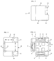
- the connector housing 1 is composed of a base body 2 ( Figures 1 to 3) and a cover 3 ( Figures 4 to 6).
- the housing 1 comprises electrical plug contacts 4, which are designed as angled plug sleeves ( Figures 7 to 9).
- the plug contacts 4 are inserted from behind into three chambers 5 of the base body 2 and secured against being pulled out by a locking hook 6, which is supported on a step 7 of the chamber 5.
- a locking hook 6 which is supported on a step 7 of the chamber 5.
- One of the plug contacts is shown in FIGS. 8 and 9.
- the plug contacts 4 are firmly attached to electrical lines 8.
- the three chambers 5 of the base body 2 are arranged in a U shape with respect to one another (FIG. 2).
- the electrical lines emerge laterally from the chambers 5 via channel-shaped channels 9.
- the plug contacts 4 connected to the lines 8 can therefore be easily inserted into the base body 2 from the rear side 10.
- an end wall 12 On the front side 11 of the base body 2 there is an end wall 12 which has a projection 13 in the opening area of the U-shape. At a distance X from the projection 13 (FIG. 1), two shoulders 14 extend, the distance Y of which corresponds to the distance of the U-legs, compare FIGS. 1 and 2.
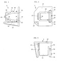
- the cover 3 (FIGS. 3 to 5) essentially consists of an end plate 15, the shape of which is adapted to the cross section of the base body 2.
- Four projections extend perpendicularly from the end plate 15.
- a first projection 16 is essentially U-shaped.
- a second projection 17 is considerably shorter, has approximately the width of the U-web 18 of the projection 16 and is arranged outside of the U-web 18 and at a short distance parallel to it.
- a third lead 19 is formed near a corner of the end plate 15. It has an angular or L-shaped cross section, see FIG. 5, and tapers towards its end in cross section.
- a fourth protrusion 20 extends near the U-opening of the protrusion 16. It has the shape of an arrowhead, see Figure 4, but is as a frame, i. H. hollow, trained. At the rear regions 21, the projection 20 is connected both to the end plate 15 and to the legs of the U-shaped projection 16, see FIG. 6. Between the regions 21 there is a recess 22 in the end plate 15, in addition to the regions 21 two recesses 23 arranged. They facilitate the shape of the projection 20.
- the rear areas 21 are followed by barbs 24, from which two legs 25 emanate, which unite in the tip 26.
- the legs 25 taper in cross section towards the tip 26, see FIG. 4.
- the assembly of the housing 1 proceeds as follows: Three plug contacts 4 struck on electrical lines 8 are pushed into the chambers 5 until the locking hooks 6 lock behind the steps 5 (first locking of the plug contacts 4).
- the lines 8 lie in the channels 9.
- the cover 3 is pushed into the base body 2 from the rear, from the side 10.
- the projections 16 to 19 serve to guide and clearly assign the cover to the base body 2.
- the projections 16 and 17 act as inner, the projection 19 as outer guide members, compare FIGS. 7 to 9.
- the tip 26 of the cover 3 abuts the projection 13 of the base body 2. Then the legs 25 bend slightly outwards as they move further, and the barbs 24 snap behind the shoulders 14 of the base housing 2.
- Suitable materials for the housing parts are customary plastics which can be processed by injection molding. The main requirement is that the housing parts are tough and elastic, but, as already mentioned above, deformations of the prefabricated parts cannot impair the good locking of the housing parts. While in the example described it is assumed that there are two separate housing parts, the invention can also be used when both housing parts are injection molded together and z. B. are connected to each other via a film hinge or the like.
Landscapes
- Engineering & Computer Science (AREA)
- Microelectronics & Electronic Packaging (AREA)
- Mechanical Engineering (AREA)
- Connector Housings Or Holding Contact Members (AREA)
- Details Of Connecting Devices For Male And Female Coupling (AREA)
- Casings For Electric Apparatus (AREA)
- Coupling Device And Connection With Printed Circuit (AREA)
Abstract
Description
- Die Erfindung betrifft ein Gehäuse nach dem Oberbegriff des Patentanspruches 1, einen elektrischen Verbinder nach dem Oberbegriff des Patentanspruches 6 und eine Verbinderanordnung nach dem Oberbegriff des Patentanspruches 7.
- Aus der Praxis sind Gehäuse für elektrische Steckverbinder bekannt, wie sie im Oberbegriff des Patentanspruches angegeben sind.
Derartige Gehäuse können oft nicht die Ansprüche an die Haltbarkeit und Festigkeit der Schnappverbindung zwischen Gehäusegrundkörper und Deckel befriedigen. Dies gilt in erhöhtem Maße, wenn die Gehäuse bei Steckverbindern in Kabelsätzen, insbesondere für die Verdrahtung von Automobilen, eingesetzt werden. Sowohl die rauhen Zustände beim Einbau in das Auto am Fließband als auch die vielfältigen Belastungen beim Gebrauch im Auto stellen hohe Ansprüche an die Schnappverbindung. - Der Erfindung liegt daher das Bestreben zugrunde, bei einem derartigen Gehäuse eine dauerhafte Verrastung der Gehäuseteile sicherzustellen und insbesondere die Verbindungskräfte zwischen den Gehäuseteilen zu erhöhen.
- Die Erfindung schlägt hierzu vor, daß die Spitze des pfeilspitzartigen Teils nach dem Verbinden unter Spannung an dem anderen Gehäuseteil so anliegt, daß von der Spitze ausgehend eine Kraft auf die Widerhaken gerichtet ist, welche die Widerhaken auseinander zu bewegen bestrebt ist. Vorteilhafte Ausgestaltungen finden sich in den Merkmalen der Unteransprüche, des weiteren ein das Gehäuse umfassender elektrischer Verbinder und eine damit gebildete Verbinderanordnung.
- Die Erfindung ist zwar anhand eines elektrischen Verbinders näher erläutert. Jedoch ist die Erfindung auch bei ähnlichen Anwendungsfällen von Gehäusen verwendbar.
- Durch die neue Gehäuseausbildung ist sichergestellt, daß nach der Montage des Gehäuses stets eine gute Verrastung zwischen den Gehäuseteilen vorliegt. Selbst wenn der pfeilspitzartige Teil der Schnappverbindung einmal verbogen, insbesondere zusammengedrückt, sein sollte, wird er durch die erfindungsgemäße Ausbildung während der Montage wieder in die ordnungsgemäße Verrastungsstellung auseinandergedrückt. Plastische Verformungen können somit nicht mehr zu Fehlfunktionen der Verrastung führen, sondern werden infolge der erfindungsgemäßen Ausbildung und Anordnung beseitigt und damit wirkungslos.
- Darüber hinaus wird die Verbindungskraft oder Haltekraft zwischen den Gehäuseteilen erhöht; d. h. es ist eine wesentlich höhere Trennkraft aufzuwenden, um die Gehäuseteile voneinander zu trennen. Beim Aufbringen einer Trennkraft auf einen der Gehäuseteile in Richtung entgegengesetzt zur Pfeilrichtung kann das elastische pfeilspitzartige Teil nicht ohne weiteres zusammengedrückt werden. Dieser stützt sich über die Pfeilspitze am anderen Gehäuseteil ab und widersetzt sich damit einem Zusammendrücken. Schließlich ist dadurch, daß das pfeilspitzartige Verriegelungsteil gegen einen Teil des anderen Gehäuseteils drückt, dieser Verriegelungsteil gegen äußere Einwirkungen geschützt, so daß ein unbeabsichtigtes Lösen der Verriegelung ausgeschlossen ist.
- In der Zeichnung ist ein Ausführungsbeispiel der Erfindung dargestellt, das im folgenden näher beschrieben wird.
- Figur 1
- zeigt den Grundkörper eines Gehäuses für einen elektrischen Steckverbinder in Seitenansicht.
- Figur 2
- zeigt den Grundkörper nach Figur 1 in Stirnansicht, d. h. von links gesehen.
- Figur 3
- zeigt den Grundkörper nach Figur 1 von unten gesehen.
- Figur 4
- zeigt den Deckel für den Grundkörper nach den Figuren 1 bis 3 in Seitenansicht.
- Figur 5
- zeigt den Deckel nach Figur 4 in Stirnansicht, d. h. von links gesehen.
- Figur 6
- zeigt den Deckel nach Figur 5 in Draufsicht.
- Figur 7
- zeigt den Zusammenbau des Gehäuses aus Grundkörper und Deckel für einen Steckverbinder.
- Figur 8
- zeigt das Gehäuse nach Figur 7 in Seitenansicht, d. h. von links gesehen, mit einem Steckkontakt.
- Figur 9
- zeigt den Schnitt IX-IX durch das Gehäuse nach Figur 8.
- Das Steckergehäuse 1 ist zusammengesetzt aus einem Grundkörper 2 (Figuren 1 bis 3) und einem Deckel 3 (Figuren 4 bis 6). Das Gehäuse 1 umfaßt elektrische Steckkontakte 4, die als Winkelsteckhülsen ausgebildet sind (Figuren 7 bis 9). Die Steckkontakte 4 sind von hinten in drei Kammern 5 des Grundkörpers 2 eingesetzt und durch einen Sperrhaken 6, der sich an einer Stufe 7 der Kammer 5 abstützt, gegen Herausziehen gesichert. In den Figuren 8 und 9 ist einer der Steckkontakte eingezeichnet. Die Steckkontakte 4 sind an elektrische Leitungen 8 fest angeschlagen.
- Die drei Kammern 5 des Grundkörpers 2 sind in U-Form zueinander angeordnet (Figur 2). Die elektrischen Leitungen treten seitlich über rinnenförmige Kanäle 9 aus den Kammern 5 aus. Die mit den Leitungen 8 verbundenen Steckkontakte 4 können demnach leicht von der hinteren Seite 10 in den Grundkörper 2 eingesetzt werden.
- An der Vorderseite 11 des Grundkörpers 2 ist eine Stirnwand 12 angeordnet, die einen Vorsprung 13 im Öffnungsbereich der U-Form aufweist. Im Abstand X zum Vorsprung 13 (Figur 1) erstrecken sich zwei Absätze 14, deren Abstand Y voneinander dem Abstand der U-Schenkel entspricht, vergleiche Figuren 1 und 2.
- Der Deckel 3 (Figuren 3 bis 5) besteht im wesentlichen aus einer Abschlußplatte 15, die in ihrer Form dem Querschnitt des Grundkörpers 2 angepaßt ist. Von der Abschlußplatte 15 erstrecken sich senkrecht hierzu vier Vorsprünge. Ein erster Vorsprung 16 ist im wesentlichen U-förmig ausgebildet. Ein zweiter Vorsprung 17 ist erheblich kürzer, hat etwa die Breite des U-Stegs 18 des Vorsprungs 16 und ist außerhalb des U-Stegs 18 sowie mit geringem Abstand parallel dazu angeordnet. Ein dritter Vorsprung 19 ist nahe einer Ecke der Abschlußplatte 15 angeformt. Er ist im Querschnitt winkel- oder L-förmig ausgebildet, siehe Figur 5, und verjüngt sich im Querschnitt zu seinem Ende hin.
- Ein vierter Vorsprung 20 erstreckt sich nahe der U-Öffnung des Vorsprungs 16. Er hat die Form einer Pfeilspitze, vergleiche Figur 4, ist jedoch als Rahmen, d. h. hohl, ausgebildet. An den hinteren Bereichen 21 ist der Vorsprung 20 sowohl mit der Abschlußplatte 15 als auch mit den Schenkeln des U-förmigen Vorsprungs 16 verbunden, vergleiche Figur 6. Zwischen den Bereichen 21 ist in der Abschlußplatte 15 eine Ausnehmung 22, neben den Bereichen 21 sind ebenfalls zwei Ausnehmungen 23 angeordnet. Sie erleichtern die Formgebung des Vorsprungs 20.
- An die hinteren Bereiche 21 schließen sich Widerhaken 24 an, von denen zwei Schenkel 25 ausgehen, die sich in der Spitze 26 vereinigen. Die Schenkel 25 verjüngen sich im Querschnitt zur Spitze 26 hin, vergleiche Figur 4.
- Der Zusammenbau des Gehäuses 1 läuft folgendermaßen ab:
Drei an elektrische Leitungen 8 angeschlagene Steckkontakte 4 werden in die Kammern 5 eingeschoben, bis sich die Sperrhaken 6 hinter den Stufen 5 verrasten (erste Verriegelung der Steckkontakte 4). Die Leitungen 8 liegen dabei in den Kanälen 9. Der Deckel 3 wird von hinten, von der Seite 10, in den Grundkörper 2 eingeschoben. Dabei dienen die Vorsprünge 16 bis zur 19 zur Führung und eindeutigen Zuordnung des Deckels zum Grundkörper 2. Beim Einschieben werden die Schenkel 25 zwischen die Absätze 14 geführt. Da der Abstand X (Figur 7) zwischen den Widerhaken 24 größer ist als der Abstand Y zwischen den Absätzen 14, wird der Vorsprung 20 im Bereich der Schenkel 25 und der Widerhaken 24 zusammengedrückt, bis die Widerhaken 24 zwischen die Absätze 14 passen. Wenn der Abstand W = Y ist, kann der Vorsprung 20 mit seiner Spitze 26 und den Schenkeln 25 die Absätze 14 passieren. Dabei wirken die Vorsprünge 16 und 17 als innere, der Vorsprung 19 als äußere Führungsglieder, vergleiche die Figuren 7 bis 9. - Am Ende des Einschiebvorganges geschieht folgendes:
Zunächst stößt die Spitze 26 des Deckels 3 auf den Vorsprung 13 des Grundkörpers 2. Dann verbiegen sich die Schenkel 25 bei weiterem Verschieben etwas nach außen, und die Widerhaken 24 schnappen hinter die Absätze 14 des Grundgehäuses 2. - Durch Vorsehen des Abstandes Z (Figur 7) zwischen der Stirnwand 12 des Grundkörpers 2 und dem U-förmigen Vorsprung 16 des Dekkels 3 ist sichergestellt, daß sich der Vorsprung 20 mit seiner Spitze 26 und seinen Widerhaken 24 zwischen dem Vorsprung 13 der Stirnwand 12 und den Absätzen 14 des Grundkörpers 2 verspannen kann.
Das hat zur Folge, daß sich die von der Spitze 26 ausgehende Kraft F in eine axiale Teilkraft F1 und in eine dazu quergerichtete Teilkraft F2 aufteilt, vergleiche Kräftedreieck in Figur 7. Die Kraft F2 bewirkt nun, daß die Widerhaken 24 auseinandergedrückt werden. Mit anderen Worten: Die Kraft F2 setzt sich einer eventuellen außen aufgebrachten oder auftretenden Lösekraft entgegen. Denn zum Lösen müssen die Widerhaken 24 sich erst wieder annähern, damit Abstand W wieder gleich Y wird, vergleiche Figur 7. Wird z. B. auf die Steckkontakte 4 oder auf ihre Leitungen 8 eine Kraft in Richtung auf die Abschlußplatte 15 des Deckels 3 ausgeübt, so stemmen sich die Schenkel 25 einem Verringern des Abstandes W entgegen. Dies bewirkt eine größere Haltekraft, die erst bei außergewöhnlich hohen äußeren Kräften überwunden werden kann. In der Regel dürfte in derartigen Fällen jedoch schon die angeschlossene Leitung 8 zerreißen, bevor sich die Schnappverbindung der Widerhaken 24 löst.
Als Material für die Gehäuseteile kommen übliche im Spritzgießverfahren verarbeitbare Kunststoffe in Betracht. Hauptvoraussetzung ist, daß die Gehäuseteile zäh-elastisch ausgebildet sind, wobei jedoch, wie oben schon erwähnt, auch Deformationen der vorfabrizierten Teile die gute Verriegelung der Gehäuseteile nicht beeinträchtigen können. Während im beschriebenen Beispiel von zwei getrennten Gehäuseteilen ausgegangen wird, kann die Erfindung aber auch dann verwendet werden, wenn beide Gehäuseteile zusammen gespritzt und z. B. über ein Filmscharnier oder dergleichen miteinander verbunden sind. -
- 1
- Steckergehäuse
- 2
- Grundkörper
- 3
- Deckel
- 4
- Steckkontakte
- 5
- Kammern
- 6
- Sperrhaken
- 7
- Stufe
- 8
- elektrische Leitung
- 9
- Kanäle
- 10
- Hinterseite von 2
- 11
- Vorderseite von 2
- 12
- Stirnwand
- 13
- Vorsprung
- 14
- Absätze
- 15
- Abschlußplatte
- 16
- 1. Vorsprung
- 17
- 2. Vorsprung
- 18
- U-Steg von 16
- 19
- 3. Vorsprung
- 20
- 4. Vorsprung
- 21
- hintere Bereiche
- 22
- Ausnehmung
- 23
- Ausnehmungen
- 24
- Widerhaken
- 25
- Schenkel
- 26
- Spitze
- W
- Abstand zwischen 24
- X
- Abstand zwischen 13 und 14
- Y
- Abstand zwischen 14
- Z
- Abstand zwischen 12 und 16
- F
- Kraft
- F1
- Teilkraft
- F2
- Teilkraft
Claims (7)
- Gehäuse (1)- aus einem Grundkörper (2) zur Aufnahme von elektrischen Bauteilen (4),- und aus einem den Grundkörper (2) zumindest auf einer Seite verschließenden Deckel (3),- mit einer Verriegelungsvorrichtung (14, 24) zwischen dem Grundkörper (2) und dem Deckel (3),dadurch gekennzeichnet, daß die Spitze (26) des pfeilspitzartigen Teils (Vorsprung 20) nach dem Verbinden unter Spannung an dem anderen Gehäuseteil (Vorsprung 13) so anliegt, daß von der Spitze (26) ausgehend eine Kraft (F 2) auf die Widerhaken (24) gerichtet ist, welche die Widerhaken (24) auseinander zu bewegen bestrebt ist.-- die aus mindestens einem elastischen, hohlen, pfeilspitzartigen Teil (Vorsprung 20) besteht,--- der beim Verbinden sich zunächst zusammendrücken läßt, jedoch dann sich elastisch spreizend mit Widerhaken (24) hinter zwei Absätze (14) des anderen Gehäuseteils (Grundkörper 2 oder Deckel 3) greift und die Verbindung der Gehäuseteile (2, 3) sichert,
- Gehäuse nach Anspruch 1, dadurch gekennzeichnet, daß der pfeilspitzartige Teil (20) am Deckel (3) und am Grundkörper (2) ein Vorsprung (13) angeordnet ist, gegen den die Spitze (26) zur Anlage kommt.
- Gehäuse nach Anspruch 1 oder 2, dadurch gekennzeichnet, daß der Deckel (3) mindestens ein Führungsglied (16 bis 19) aufweist, das sich in Pfeilrichtung erstreckt.
- Gehäuse nach Anspruch 3, dadurch gekennzeichnet, daß das Führungsglied (16 bis 19) im Querschnitt eine L- oder U-Form auf- weist (Fig. 5).
- Gehäuse nach Anspruch 3 oder 4, dadurch gekennzeichnet, daß das Führungsglied bzw. die Führungsglieder (16 bis 19) innerhalb und/oder außerhalb des Grundkörpers (2) angeordnet ist bzw. sind.
- Elektrischer Steckverbinder mit einem Gehäuse nach einem der Ansprüche 1 bis 5, dadurch gekennzeichnet, daß im Gehäuse (1) mindestens ein Steckkontakt (4) angeordnet ist, der durch den Deckel (3) allein oder zusätzlich im Grundkörper (2) gehalten ist.
- Verbinderanordnung mit einem elektrischen Steckverbinder nach Anspruch 6, dadurch gekennzeichnet,- daß drei Kammern (5) und drei Steckkontakte (4) in U-Form angeordnet sind,- daß die Steckkontakte (4) als Winkelsteckhülsen ausgebildet sind,- daß die Winkelsteckhülsen fest mit elektrischen, isolierten Leitungen (8) verbunden sind,- daß die elektrischen Leitungen (8) in rinnenförmige Kanäle (9) des Grundkörpers (2) eingelegt sind und- daß die Kammern (5) und die Kanäle (9) von dem Deckel (3) abgedeckt sind.
Applications Claiming Priority (2)
| Application Number | Priority Date | Filing Date | Title |
|---|---|---|---|
| DE4142525 | 1991-12-21 | ||
| DE4142525A DE4142525C1 (de) | 1991-12-21 | 1991-12-21 |
Publications (2)
| Publication Number | Publication Date |
|---|---|
| EP0548701A1 true EP0548701A1 (de) | 1993-06-30 |
| EP0548701B1 EP0548701B1 (de) | 1995-05-17 |
Family
ID=6447847
Family Applications (1)
| Application Number | Title | Priority Date | Filing Date |
|---|---|---|---|
| EP92121105A Expired - Lifetime EP0548701B1 (de) | 1991-12-21 | 1992-12-11 | Gehäuse, elektrischer Verbinder und Verbinderanordnung |
Country Status (4)
| Country | Link |
|---|---|
| EP (1) | EP0548701B1 (de) |
| AT (1) | ATE122823T1 (de) |
| DE (2) | DE4142525C1 (de) |
| ES (1) | ES2073849T3 (de) |
Families Citing this family (3)
| Publication number | Priority date | Publication date | Assignee | Title |
|---|---|---|---|---|
| DE4431281A1 (de) * | 1994-09-02 | 1996-03-07 | Teves Gmbh Alfred | Rastverbindung von Gehäuseteilen mit integriertem Sicherungsstift |
| DE4431859C1 (de) * | 1994-09-07 | 1996-01-04 | Reinshagen Kabelwerk Gmbh | Dose zum Einbau in einem Motorraum und zur Aufnahme elektrischer Bauteile und deren Leitungsanschlüsse |
| EP0714228B1 (de) * | 1994-11-22 | 1999-09-15 | DODUCO GmbH | Zweiteiliges Gehäuse aus Kunststoff zum Aufnehmen einer elektronischen Schaltung |
Citations (2)
| Publication number | Priority date | Publication date | Assignee | Title |
|---|---|---|---|---|
| FR2153752A5 (de) * | 1971-09-23 | 1973-05-04 | Labinal | |
| DE8908758U1 (de) * | 1989-07-19 | 1989-09-07 | Bär Elektrowerke GmbH & Co KG, 58579 Schalksmühle | Elektrisches Gerät, insbesondere Haushaltsgerät |
Family Cites Families (5)
| Publication number | Priority date | Publication date | Assignee | Title |
|---|---|---|---|---|
| DE2616333A1 (de) * | 1976-04-14 | 1977-11-03 | Siemens Ag | Vorrichtung zum befestigen und abstuetzen von leiterplatten |
| DE2901213C2 (de) * | 1979-01-13 | 1985-05-09 | Brown, Boveri & Cie Ag, 6800 Mannheim | Lösbare Stiftverbindung für Bauelemente |
| DE3103534C2 (de) * | 1981-02-03 | 1983-09-08 | Varta Batterie Ag, 3000 Hannover | Batteriegehäuse aus Kunststoff |
| GB2130805B (en) * | 1982-11-12 | 1986-03-26 | Kitagawa Ind Co Ltd | Spacer for spacing apart wiring boards |
| US4760495A (en) * | 1987-04-16 | 1988-07-26 | Prime Computer Inc. | Stand-off device |
-
1991
- 1991-12-21 DE DE4142525A patent/DE4142525C1/de not_active Expired - Fee Related
-
1992
- 1992-12-11 ES ES92121105T patent/ES2073849T3/es not_active Expired - Lifetime
- 1992-12-11 EP EP92121105A patent/EP0548701B1/de not_active Expired - Lifetime
- 1992-12-11 AT AT92121105T patent/ATE122823T1/de not_active IP Right Cessation
- 1992-12-11 DE DE59202244T patent/DE59202244D1/de not_active Expired - Lifetime
Patent Citations (2)
| Publication number | Priority date | Publication date | Assignee | Title |
|---|---|---|---|---|
| FR2153752A5 (de) * | 1971-09-23 | 1973-05-04 | Labinal | |
| DE8908758U1 (de) * | 1989-07-19 | 1989-09-07 | Bär Elektrowerke GmbH & Co KG, 58579 Schalksmühle | Elektrisches Gerät, insbesondere Haushaltsgerät |
Also Published As
| Publication number | Publication date |
|---|---|
| EP0548701B1 (de) | 1995-05-17 |
| ES2073849T3 (es) | 1995-08-16 |
| DE59202244D1 (de) | 1995-06-22 |
| DE4142525C1 (de) | 1993-06-03 |
| ATE122823T1 (de) | 1995-06-15 |
Similar Documents
| Publication | Publication Date | Title |
|---|---|---|
| DE19812935C2 (de) | Elektrisches Steckverbinder-Anschlußstück | |
| DE69503315T2 (de) | Hermaphroditisches elektrisches Kontaktelement | |
| DE69032353T2 (de) | Elektrischer Verbinder für Brennstoffinjektor und Anschlüsse dazu | |
| DE69200607T2 (de) | Elektrische Verbindung und Gehäuse für elektrische Bauteile mit einer solchen Verbindung. | |
| EP3961821B1 (de) | Verbindungsvorrichtung mit einem steckverbinder und einem gegensteckverbinder | |
| DE102011055919A1 (de) | Anschlussklemme | |
| DE2931441A1 (de) | Erdvorrichtung | |
| DE102016121967A1 (de) | Elektrische Anschluss- sowie Verbindungsklemme | |
| DE102013217787A1 (de) | Elektrische Anschlussdose | |
| DE102021126788A1 (de) | Radschutzvorrichtung für ein Zweirad | |
| EP0548701B1 (de) | Gehäuse, elektrischer Verbinder und Verbinderanordnung | |
| EP1503460A1 (de) | Kabelabdichtung für einen Steckverbinder | |
| EP0424806B1 (de) | Anordnung zum Fixieren eines mechanischen und/oder elektrischen Verbindungselementes, insbesondere einer Kontaktfeder | |
| DE29619139U1 (de) | Anschlußstück für Cageclamp-Anschlußtechnik | |
| DE102023122401A1 (de) | Elektrischer Verbinder für ein abgedichtetesInline-Verbindungssystem ohne Anschlussklemme | |
| DE9115903U1 (de) | Gehäuse, elektrischer Verbinder und Verbinderanordnung | |
| EP1720222B1 (de) | Steckverbinder, insbesondere für Airbag-Zündsysteme | |
| EP1303008B1 (de) | Verbinderteil eines elektrischen Steckverbinders | |
| DE20110120U1 (de) | Zylindrisches Verbindungsteil mit Batterieklemme | |
| DE102004003907B4 (de) | Klips | |
| DE102020203637A1 (de) | Steckverbinder mit dichtungselement an einer anlagefläche | |
| DE8702252U1 (de) | Hochspannungsbauteil | |
| DE19742934B4 (de) | Kontakt, Verbindergehäuse und elektrische Verbinderanordnung bestehend aus Kontakt und Verbindergehäuse | |
| EP1469568B1 (de) | Steckkontaktelement und Verfahren zur Herstellung eines Gehäuseteils für dieses | |
| WO2003067715A1 (de) | Gehäuse mit integrierter zugentlastung |
Legal Events
| Date | Code | Title | Description |
|---|---|---|---|
| PUAI | Public reference made under article 153(3) epc to a published international application that has entered the european phase |
Free format text: ORIGINAL CODE: 0009012 |
|
| 17P | Request for examination filed |
Effective date: 19930428 |
|
| AK | Designated contracting states |
Kind code of ref document: A1 Designated state(s): AT BE DE ES FR GB IE IT PT SE |
|
| 17Q | First examination report despatched |
Effective date: 19941027 |
|
| GRAA | (expected) grant |
Free format text: ORIGINAL CODE: 0009210 |
|
| AK | Designated contracting states |
Kind code of ref document: B1 Designated state(s): AT BE DE ES FR GB IE IT PT SE |
|
| PG25 | Lapsed in a contracting state [announced via postgrant information from national office to epo] |
Ref country code: BE Effective date: 19950517 |
|
| REF | Corresponds to: |
Ref document number: 122823 Country of ref document: AT Date of ref document: 19950615 Kind code of ref document: T |
|
| REG | Reference to a national code |
Ref country code: IE Ref legal event code: FG4D Free format text: 63781 |
|
| ITF | It: translation for a ep patent filed | ||
| REF | Corresponds to: |
Ref document number: 59202244 Country of ref document: DE Date of ref document: 19950622 |
|
| GBT | Gb: translation of ep patent filed (gb section 77(6)(a)/1977) |
Effective date: 19950525 |
|
| REG | Reference to a national code |
Ref country code: ES Ref legal event code: FG2A Ref document number: 2073849 Country of ref document: ES Kind code of ref document: T3 |
|
| PG25 | Lapsed in a contracting state [announced via postgrant information from national office to epo] |
Ref country code: SE Effective date: 19950817 Ref country code: PT Effective date: 19950817 |
|
| ET | Fr: translation filed | ||
| RAP2 | Party data changed (patent owner data changed or rights of a patent transferred) |
Owner name: DELPHI AUTOMOTIVE SYSTEMS DEUTSCHLAND GMBH |
|
| PG25 | Lapsed in a contracting state [announced via postgrant information from national office to epo] |
Ref country code: AT Effective date: 19951211 |
|
| REG | Reference to a national code |
Ref country code: IE Ref legal event code: FD4D Ref document number: 63781 Country of ref document: IE |
|
| PG25 | Lapsed in a contracting state [announced via postgrant information from national office to epo] |
Ref country code: IE Free format text: LAPSE BECAUSE OF NON-PAYMENT OF DUE FEES Effective date: 19951231 |
|
| PLBE | No opposition filed within time limit |
Free format text: ORIGINAL CODE: 0009261 |
|
| STAA | Information on the status of an ep patent application or granted ep patent |
Free format text: STATUS: NO OPPOSITION FILED WITHIN TIME LIMIT |
|
| REG | Reference to a national code |
Ref country code: FR Ref legal event code: CD |
|
| 26N | No opposition filed | ||
| REG | Reference to a national code |
Ref country code: GB Ref legal event code: IF02 |
|
| PGFP | Annual fee paid to national office [announced via postgrant information from national office to epo] |
Ref country code: GB Payment date: 20031128 Year of fee payment: 12 |
|
| PGFP | Annual fee paid to national office [announced via postgrant information from national office to epo] |
Ref country code: ES Payment date: 20031223 Year of fee payment: 12 |
|
| PG25 | Lapsed in a contracting state [announced via postgrant information from national office to epo] |
Ref country code: GB Free format text: LAPSE BECAUSE OF NON-PAYMENT OF DUE FEES Effective date: 20041211 |
|
| PG25 | Lapsed in a contracting state [announced via postgrant information from national office to epo] |
Ref country code: ES Free format text: LAPSE BECAUSE OF NON-PAYMENT OF DUE FEES Effective date: 20041213 |
|
| GBPC | Gb: european patent ceased through non-payment of renewal fee |
Effective date: 20041211 |
|
| REG | Reference to a national code |
Ref country code: ES Ref legal event code: FD2A Effective date: 20041213 |
|
| PGFP | Annual fee paid to national office [announced via postgrant information from national office to epo] |
Ref country code: IT Payment date: 20101218 Year of fee payment: 19 |
|
| PGFP | Annual fee paid to national office [announced via postgrant information from national office to epo] |
Ref country code: DE Payment date: 20101208 Year of fee payment: 19 |
|
| PGFP | Annual fee paid to national office [announced via postgrant information from national office to epo] |
Ref country code: FR Payment date: 20111219 Year of fee payment: 20 |
|
| REG | Reference to a national code |
Ref country code: DE Ref legal event code: R071 Ref document number: 59202244 Country of ref document: DE |
|
| REG | Reference to a national code |
Ref country code: DE Ref legal event code: R071 Ref document number: 59202244 Country of ref document: DE |