EP0548701A1 - Boîtier de connecteurs électriques et agencement de connexion - Google Patents
Boîtier de connecteurs électriques et agencement de connexion Download PDFInfo
- Publication number
- EP0548701A1 EP0548701A1 EP92121105A EP92121105A EP0548701A1 EP 0548701 A1 EP0548701 A1 EP 0548701A1 EP 92121105 A EP92121105 A EP 92121105A EP 92121105 A EP92121105 A EP 92121105A EP 0548701 A1 EP0548701 A1 EP 0548701A1
- Authority
- EP
- European Patent Office
- Prior art keywords
- housing
- base body
- cover
- projection
- barbs
- Prior art date
- Legal status (The legal status is an assumption and is not a legal conclusion. Google has not performed a legal analysis and makes no representation as to the accuracy of the status listed.)
- Granted
Links
- 229920003023 plastic Polymers 0.000 description 2
- 239000004033 plastic Substances 0.000 description 2
- 230000006835 compression Effects 0.000 description 1
- 238000007906 compression Methods 0.000 description 1
- 238000002347 injection Methods 0.000 description 1
- 239000007924 injection Substances 0.000 description 1
- 238000001746 injection moulding Methods 0.000 description 1
- 238000003780 insertion Methods 0.000 description 1
- 230000037431 insertion Effects 0.000 description 1
- 230000007257 malfunction Effects 0.000 description 1
- 239000000463 material Substances 0.000 description 1
- 238000000034 method Methods 0.000 description 1
- 238000000926 separation method Methods 0.000 description 1
Images

Classifications
-
- B—PERFORMING OPERATIONS; TRANSPORTING
- B60—VEHICLES IN GENERAL
- B60R—VEHICLES, VEHICLE FITTINGS, OR VEHICLE PARTS, NOT OTHERWISE PROVIDED FOR
- B60R16/00—Electric or fluid circuits specially adapted for vehicles and not otherwise provided for; Arrangement of elements of electric or fluid circuits specially adapted for vehicles and not otherwise provided for
- B60R16/02—Electric or fluid circuits specially adapted for vehicles and not otherwise provided for; Arrangement of elements of electric or fluid circuits specially adapted for vehicles and not otherwise provided for electric constitutive elements
- B60R16/023—Electric or fluid circuits specially adapted for vehicles and not otherwise provided for; Arrangement of elements of electric or fluid circuits specially adapted for vehicles and not otherwise provided for electric constitutive elements for transmission of signals between vehicle parts or subsystems
- B60R16/0239—Electronic boxes
-
- H—ELECTRICITY
- H01—ELECTRIC ELEMENTS
- H01R—ELECTRICALLY-CONDUCTIVE CONNECTIONS; STRUCTURAL ASSOCIATIONS OF A PLURALITY OF MUTUALLY-INSULATED ELECTRICAL CONNECTING ELEMENTS; COUPLING DEVICES; CURRENT COLLECTORS
- H01R13/00—Details of coupling devices of the kinds covered by groups H01R12/70 or H01R24/00 - H01R33/00
- H01R13/46—Bases; Cases
- H01R13/502—Bases; Cases composed of different pieces
- H01R13/506—Bases; Cases composed of different pieces assembled by snap action of the parts
-
- H—ELECTRICITY
- H05—ELECTRIC TECHNIQUES NOT OTHERWISE PROVIDED FOR
- H05K—PRINTED CIRCUITS; CASINGS OR CONSTRUCTIONAL DETAILS OF ELECTRIC APPARATUS; MANUFACTURE OF ASSEMBLAGES OF ELECTRICAL COMPONENTS
- H05K5/00—Casings, cabinets or drawers for electric apparatus
- H05K5/10—Casings, cabinets or drawers for electric apparatus comprising several parts forming a closed casing
- H05K5/15—Casings, cabinets or drawers for electric apparatus comprising several parts forming a closed casing assembled by resilient members
Definitions
- the invention relates to a housing according to the preamble of patent claim 1, an electrical connector according to the preamble of patent claim 6 and a connector arrangement according to the preamble of patent claim 7.
- Housings for electrical connectors are known from practice, as specified in the preamble of the claim. Such housings can often not meet the requirements for durability and strength of the snap connection between the housing base and the cover. This applies to an increased extent if the housings are used for connectors in cable sets, in particular for the wiring of automobiles. Both the rough conditions when installed in the car on the assembly line and the various loads when used in the car place high demands on the snap connection.
- the invention is therefore based on the endeavor to ensure permanent locking of the housing parts in such a housing and in particular to increase the connecting forces between the housing parts.
- the invention proposes that the tip of the arrowhead-like part, after being connected under tension, rests against the other housing part in such a way that, starting from the tip, a force is directed onto the barbs which tends to move the barbs apart.
- Advantageous configurations can be found in the features of the subclaims, furthermore an electrical connector comprising the housing and a connector arrangement formed therewith.
- the new housing design ensures that there is always a good locking between the housing parts after the housing has been installed. Even if the arrowhead-like part of the snap connection should be bent, in particular compressed, it is pushed apart again into the correct latching position by the inventive design during assembly. Plastic deformations can therefore no longer lead to malfunctions in the latching, but are eliminated as a result of the design and arrangement according to the invention and are therefore ineffective.
- the connecting force or holding force between the housing parts is increased; d. H. a much higher separation force has to be used to separate the housing parts.
- a separating force is applied to one of the housing parts in the direction opposite to the direction of the arrow, the elastic arrowhead-like part cannot simply be compressed. This is supported by the arrowhead on the other housing part and thus opposes compression.
- the arrowhead-like locking part presses against a part of the other housing part, this locking part is protected against external influences, so that an unintentional release of the lock is excluded.
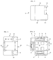
- the connector housing 1 is composed of a base body 2 ( Figures 1 to 3) and a cover 3 ( Figures 4 to 6).
- the housing 1 comprises electrical plug contacts 4, which are designed as angled plug sleeves ( Figures 7 to 9).
- the plug contacts 4 are inserted from behind into three chambers 5 of the base body 2 and secured against being pulled out by a locking hook 6, which is supported on a step 7 of the chamber 5.
- a locking hook 6 which is supported on a step 7 of the chamber 5.
- One of the plug contacts is shown in FIGS. 8 and 9.
- the plug contacts 4 are firmly attached to electrical lines 8.
- the three chambers 5 of the base body 2 are arranged in a U shape with respect to one another (FIG. 2).
- the electrical lines emerge laterally from the chambers 5 via channel-shaped channels 9.
- the plug contacts 4 connected to the lines 8 can therefore be easily inserted into the base body 2 from the rear side 10.
- an end wall 12 On the front side 11 of the base body 2 there is an end wall 12 which has a projection 13 in the opening area of the U-shape. At a distance X from the projection 13 (FIG. 1), two shoulders 14 extend, the distance Y of which corresponds to the distance of the U-legs, compare FIGS. 1 and 2.
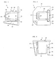
- the cover 3 (FIGS. 3 to 5) essentially consists of an end plate 15, the shape of which is adapted to the cross section of the base body 2.
- Four projections extend perpendicularly from the end plate 15.
- a first projection 16 is essentially U-shaped.
- a second projection 17 is considerably shorter, has approximately the width of the U-web 18 of the projection 16 and is arranged outside of the U-web 18 and at a short distance parallel to it.
- a third lead 19 is formed near a corner of the end plate 15. It has an angular or L-shaped cross section, see FIG. 5, and tapers towards its end in cross section.
- a fourth protrusion 20 extends near the U-opening of the protrusion 16. It has the shape of an arrowhead, see Figure 4, but is as a frame, i. H. hollow, trained. At the rear regions 21, the projection 20 is connected both to the end plate 15 and to the legs of the U-shaped projection 16, see FIG. 6. Between the regions 21 there is a recess 22 in the end plate 15, in addition to the regions 21 two recesses 23 arranged. They facilitate the shape of the projection 20.
- the rear areas 21 are followed by barbs 24, from which two legs 25 emanate, which unite in the tip 26.
- the legs 25 taper in cross section towards the tip 26, see FIG. 4.
- the assembly of the housing 1 proceeds as follows: Three plug contacts 4 struck on electrical lines 8 are pushed into the chambers 5 until the locking hooks 6 lock behind the steps 5 (first locking of the plug contacts 4).
- the lines 8 lie in the channels 9.
- the cover 3 is pushed into the base body 2 from the rear, from the side 10.
- the projections 16 to 19 serve to guide and clearly assign the cover to the base body 2.
- the projections 16 and 17 act as inner, the projection 19 as outer guide members, compare FIGS. 7 to 9.
- the tip 26 of the cover 3 abuts the projection 13 of the base body 2. Then the legs 25 bend slightly outwards as they move further, and the barbs 24 snap behind the shoulders 14 of the base housing 2.
- Suitable materials for the housing parts are customary plastics which can be processed by injection molding. The main requirement is that the housing parts are tough and elastic, but, as already mentioned above, deformations of the prefabricated parts cannot impair the good locking of the housing parts. While in the example described it is assumed that there are two separate housing parts, the invention can also be used when both housing parts are injection molded together and z. B. are connected to each other via a film hinge or the like.
Landscapes
- Engineering & Computer Science (AREA)
- Microelectronics & Electronic Packaging (AREA)
- Mechanical Engineering (AREA)
- Connector Housings Or Holding Contact Members (AREA)
- Details Of Connecting Devices For Male And Female Coupling (AREA)
- Casings For Electric Apparatus (AREA)
- Coupling Device And Connection With Printed Circuit (AREA)
Applications Claiming Priority (2)
| Application Number | Priority Date | Filing Date | Title |
|---|---|---|---|
| DE4142525 | 1991-12-21 | ||
| DE4142525A DE4142525C1 (fr) | 1991-12-21 | 1991-12-21 |
Publications (2)
| Publication Number | Publication Date |
|---|---|
| EP0548701A1 true EP0548701A1 (fr) | 1993-06-30 |
| EP0548701B1 EP0548701B1 (fr) | 1995-05-17 |
Family
ID=6447847
Family Applications (1)
| Application Number | Title | Priority Date | Filing Date |
|---|---|---|---|
| EP92121105A Expired - Lifetime EP0548701B1 (fr) | 1991-12-21 | 1992-12-11 | Boîtier de connecteurs électriques et agencement de connexion |
Country Status (4)
| Country | Link |
|---|---|
| EP (1) | EP0548701B1 (fr) |
| AT (1) | ATE122823T1 (fr) |
| DE (2) | DE4142525C1 (fr) |
| ES (1) | ES2073849T3 (fr) |
Families Citing this family (3)
| Publication number | Priority date | Publication date | Assignee | Title |
|---|---|---|---|---|
| DE4431281A1 (de) * | 1994-09-02 | 1996-03-07 | Teves Gmbh Alfred | Rastverbindung von Gehäuseteilen mit integriertem Sicherungsstift |
| DE4431859C1 (de) * | 1994-09-07 | 1996-01-04 | Reinshagen Kabelwerk Gmbh | Dose zum Einbau in einem Motorraum und zur Aufnahme elektrischer Bauteile und deren Leitungsanschlüsse |
| EP0714228B1 (fr) * | 1994-11-22 | 1999-09-15 | DODUCO GmbH | Boítier en deux parties en matière plastique pour loger un circuit électronique |
Citations (2)
| Publication number | Priority date | Publication date | Assignee | Title |
|---|---|---|---|---|
| FR2153752A5 (fr) * | 1971-09-23 | 1973-05-04 | Labinal | |
| DE8908758U1 (de) * | 1989-07-19 | 1989-09-07 | Bär Elektrowerke GmbH & Co KG, 58579 Schalksmühle | Elektrisches Gerät, insbesondere Haushaltsgerät |
Family Cites Families (5)
| Publication number | Priority date | Publication date | Assignee | Title |
|---|---|---|---|---|
| DE2616333A1 (de) * | 1976-04-14 | 1977-11-03 | Siemens Ag | Vorrichtung zum befestigen und abstuetzen von leiterplatten |
| DE2901213C2 (de) * | 1979-01-13 | 1985-05-09 | Brown, Boveri & Cie Ag, 6800 Mannheim | Lösbare Stiftverbindung für Bauelemente |
| DE3103534C2 (de) * | 1981-02-03 | 1983-09-08 | Varta Batterie Ag, 3000 Hannover | Batteriegehäuse aus Kunststoff |
| GB2130805B (en) * | 1982-11-12 | 1986-03-26 | Kitagawa Ind Co Ltd | Spacer for spacing apart wiring boards |
| US4760495A (en) * | 1987-04-16 | 1988-07-26 | Prime Computer Inc. | Stand-off device |
-
1991
- 1991-12-21 DE DE4142525A patent/DE4142525C1/de not_active Expired - Fee Related
-
1992
- 1992-12-11 ES ES92121105T patent/ES2073849T3/es not_active Expired - Lifetime
- 1992-12-11 EP EP92121105A patent/EP0548701B1/fr not_active Expired - Lifetime
- 1992-12-11 AT AT92121105T patent/ATE122823T1/de not_active IP Right Cessation
- 1992-12-11 DE DE59202244T patent/DE59202244D1/de not_active Expired - Lifetime
Patent Citations (2)
| Publication number | Priority date | Publication date | Assignee | Title |
|---|---|---|---|---|
| FR2153752A5 (fr) * | 1971-09-23 | 1973-05-04 | Labinal | |
| DE8908758U1 (de) * | 1989-07-19 | 1989-09-07 | Bär Elektrowerke GmbH & Co KG, 58579 Schalksmühle | Elektrisches Gerät, insbesondere Haushaltsgerät |
Also Published As
| Publication number | Publication date |
|---|---|
| EP0548701B1 (fr) | 1995-05-17 |
| ES2073849T3 (es) | 1995-08-16 |
| DE59202244D1 (de) | 1995-06-22 |
| DE4142525C1 (fr) | 1993-06-03 |
| ATE122823T1 (de) | 1995-06-15 |
Similar Documents
| Publication | Publication Date | Title |
|---|---|---|
| DE19812935C2 (de) | Elektrisches Steckverbinder-Anschlußstück | |
| DE69503315T2 (de) | Hermaphroditisches elektrisches Kontaktelement | |
| DE69032353T2 (de) | Elektrischer Verbinder für Brennstoffinjektor und Anschlüsse dazu | |
| DE69200607T2 (de) | Elektrische Verbindung und Gehäuse für elektrische Bauteile mit einer solchen Verbindung. | |
| EP3961821B1 (fr) | Dispositif de connexion doté d'un connecteur enfichable et d'un connecteur enfichable complémentaire | |
| DE102011055919A1 (de) | Anschlussklemme | |
| DE2931441A1 (de) | Erdvorrichtung | |
| DE102016121967A1 (de) | Elektrische Anschluss- sowie Verbindungsklemme | |
| DE102013217787A1 (de) | Elektrische Anschlussdose | |
| DE102021126788A1 (de) | Radschutzvorrichtung für ein Zweirad | |
| EP0548701B1 (fr) | Boîtier de connecteurs électriques et agencement de connexion | |
| EP1503460A1 (fr) | Joint d'étanchéité pour câble pour un connecteur à fiche | |
| EP0424806B1 (fr) | Dispositif pour fixer un organe de connexion électrique et/ou mécanique, notamment un ressort de contact | |
| DE29619139U1 (de) | Anschlußstück für Cageclamp-Anschlußtechnik | |
| DE102023122401A1 (de) | Elektrischer Verbinder für ein abgedichtetesInline-Verbindungssystem ohne Anschlussklemme | |
| DE9115903U1 (de) | Gehäuse, elektrischer Verbinder und Verbinderanordnung | |
| EP1720222B1 (fr) | Connecteur électrique, notamment pour des systèmes d' allumage d' airbag | |
| EP1303008B1 (fr) | Partie de liaison d'un connecteur électrique | |
| DE20110120U1 (de) | Zylindrisches Verbindungsteil mit Batterieklemme | |
| DE102004003907B4 (de) | Klips | |
| DE102020203637A1 (de) | Steckverbinder mit dichtungselement an einer anlagefläche | |
| DE8702252U1 (de) | Hochspannungsbauteil | |
| DE19742934B4 (de) | Kontakt, Verbindergehäuse und elektrische Verbinderanordnung bestehend aus Kontakt und Verbindergehäuse | |
| EP1469568B1 (fr) | Borne femelle et procédé de fabrication d' une pièce de son boîtier | |
| WO2003067715A1 (fr) | Boitier avec element de decharge de tension integre |
Legal Events
| Date | Code | Title | Description |
|---|---|---|---|
| PUAI | Public reference made under article 153(3) epc to a published international application that has entered the european phase |
Free format text: ORIGINAL CODE: 0009012 |
|
| 17P | Request for examination filed |
Effective date: 19930428 |
|
| AK | Designated contracting states |
Kind code of ref document: A1 Designated state(s): AT BE DE ES FR GB IE IT PT SE |
|
| 17Q | First examination report despatched |
Effective date: 19941027 |
|
| GRAA | (expected) grant |
Free format text: ORIGINAL CODE: 0009210 |
|
| AK | Designated contracting states |
Kind code of ref document: B1 Designated state(s): AT BE DE ES FR GB IE IT PT SE |
|
| PG25 | Lapsed in a contracting state [announced via postgrant information from national office to epo] |
Ref country code: BE Effective date: 19950517 |
|
| REF | Corresponds to: |
Ref document number: 122823 Country of ref document: AT Date of ref document: 19950615 Kind code of ref document: T |
|
| REG | Reference to a national code |
Ref country code: IE Ref legal event code: FG4D Free format text: 63781 |
|
| ITF | It: translation for a ep patent filed | ||
| REF | Corresponds to: |
Ref document number: 59202244 Country of ref document: DE Date of ref document: 19950622 |
|
| GBT | Gb: translation of ep patent filed (gb section 77(6)(a)/1977) |
Effective date: 19950525 |
|
| REG | Reference to a national code |
Ref country code: ES Ref legal event code: FG2A Ref document number: 2073849 Country of ref document: ES Kind code of ref document: T3 |
|
| PG25 | Lapsed in a contracting state [announced via postgrant information from national office to epo] |
Ref country code: SE Effective date: 19950817 Ref country code: PT Effective date: 19950817 |
|
| ET | Fr: translation filed | ||
| RAP2 | Party data changed (patent owner data changed or rights of a patent transferred) |
Owner name: DELPHI AUTOMOTIVE SYSTEMS DEUTSCHLAND GMBH |
|
| PG25 | Lapsed in a contracting state [announced via postgrant information from national office to epo] |
Ref country code: AT Effective date: 19951211 |
|
| REG | Reference to a national code |
Ref country code: IE Ref legal event code: FD4D Ref document number: 63781 Country of ref document: IE |
|
| PG25 | Lapsed in a contracting state [announced via postgrant information from national office to epo] |
Ref country code: IE Free format text: LAPSE BECAUSE OF NON-PAYMENT OF DUE FEES Effective date: 19951231 |
|
| PLBE | No opposition filed within time limit |
Free format text: ORIGINAL CODE: 0009261 |
|
| STAA | Information on the status of an ep patent application or granted ep patent |
Free format text: STATUS: NO OPPOSITION FILED WITHIN TIME LIMIT |
|
| REG | Reference to a national code |
Ref country code: FR Ref legal event code: CD |
|
| 26N | No opposition filed | ||
| REG | Reference to a national code |
Ref country code: GB Ref legal event code: IF02 |
|
| PGFP | Annual fee paid to national office [announced via postgrant information from national office to epo] |
Ref country code: GB Payment date: 20031128 Year of fee payment: 12 |
|
| PGFP | Annual fee paid to national office [announced via postgrant information from national office to epo] |
Ref country code: ES Payment date: 20031223 Year of fee payment: 12 |
|
| PG25 | Lapsed in a contracting state [announced via postgrant information from national office to epo] |
Ref country code: GB Free format text: LAPSE BECAUSE OF NON-PAYMENT OF DUE FEES Effective date: 20041211 |
|
| PG25 | Lapsed in a contracting state [announced via postgrant information from national office to epo] |
Ref country code: ES Free format text: LAPSE BECAUSE OF NON-PAYMENT OF DUE FEES Effective date: 20041213 |
|
| GBPC | Gb: european patent ceased through non-payment of renewal fee |
Effective date: 20041211 |
|
| REG | Reference to a national code |
Ref country code: ES Ref legal event code: FD2A Effective date: 20041213 |
|
| PGFP | Annual fee paid to national office [announced via postgrant information from national office to epo] |
Ref country code: IT Payment date: 20101218 Year of fee payment: 19 |
|
| PGFP | Annual fee paid to national office [announced via postgrant information from national office to epo] |
Ref country code: DE Payment date: 20101208 Year of fee payment: 19 |
|
| PGFP | Annual fee paid to national office [announced via postgrant information from national office to epo] |
Ref country code: FR Payment date: 20111219 Year of fee payment: 20 |
|
| REG | Reference to a national code |
Ref country code: DE Ref legal event code: R071 Ref document number: 59202244 Country of ref document: DE |
|
| REG | Reference to a national code |
Ref country code: DE Ref legal event code: R071 Ref document number: 59202244 Country of ref document: DE |