EP0548806A2 - Fixation de ski - Google Patents
Fixation de ski Download PDFInfo
- Publication number
- EP0548806A2 EP0548806A2 EP92121491A EP92121491A EP0548806A2 EP 0548806 A2 EP0548806 A2 EP 0548806A2 EP 92121491 A EP92121491 A EP 92121491A EP 92121491 A EP92121491 A EP 92121491A EP 0548806 A2 EP0548806 A2 EP 0548806A2
- Authority
- EP
- European Patent Office
- Prior art keywords
- ski
- tension member
- boot
- heel
- binding according
- Prior art date
- Legal status (The legal status is an assumption and is not a legal conclusion. Google has not performed a legal analysis and makes no representation as to the accuracy of the status listed.)
- Granted
Links
Images









Classifications
-
- A—HUMAN NECESSITIES
- A63—SPORTS; GAMES; AMUSEMENTS
- A63C—SKATES; SKIS; ROLLER SKATES; DESIGN OR LAYOUT OF COURTS, RINKS OR THE LIKE
- A63C9/00—Ski bindings
- A63C9/08—Ski bindings yieldable or self-releasing in the event of an accident, i.e. safety bindings
- A63C9/086—Ski bindings yieldable or self-releasing in the event of an accident, i.e. safety bindings using parts which are fixed on the shoe of the user and are releasable from the ski binding
-
- A—HUMAN NECESSITIES
- A63—SPORTS; GAMES; AMUSEMENTS
- A63C—SKATES; SKIS; ROLLER SKATES; DESIGN OR LAYOUT OF COURTS, RINKS OR THE LIKE
- A63C9/00—Ski bindings
- A63C9/02—Non-self-releasing bindings with swivel sole-plate or swivel parts, i.e. Ellefsen-type
-
- A—HUMAN NECESSITIES
- A63—SPORTS; GAMES; AMUSEMENTS
- A63C—SKATES; SKIS; ROLLER SKATES; DESIGN OR LAYOUT OF COURTS, RINKS OR THE LIKE
- A63C9/00—Ski bindings
- A63C9/08—Ski bindings yieldable or self-releasing in the event of an accident, i.e. safety bindings
- A63C9/0807—Ski bindings yieldable or self-releasing in the event of an accident, i.e. safety bindings for both towing and downhill skiing
-
- A—HUMAN NECESSITIES
- A63—SPORTS; GAMES; AMUSEMENTS
- A63C—SKATES; SKIS; ROLLER SKATES; DESIGN OR LAYOUT OF COURTS, RINKS OR THE LIKE
- A63C9/00—Ski bindings
- A63C9/08—Ski bindings yieldable or self-releasing in the event of an accident, i.e. safety bindings
- A63C9/081—Ski bindings yieldable or self-releasing in the event of an accident, i.e. safety bindings with swivel sole-plate
-
- A—HUMAN NECESSITIES
- A63—SPORTS; GAMES; AMUSEMENTS
- A63C—SKATES; SKIS; ROLLER SKATES; DESIGN OR LAYOUT OF COURTS, RINKS OR THE LIKE
- A63C9/00—Ski bindings
- A63C9/08—Ski bindings yieldable or self-releasing in the event of an accident, i.e. safety bindings
- A63C9/083—Ski bindings yieldable or self-releasing in the event of an accident, i.e. safety bindings with loosenable cable strap
-
- A—HUMAN NECESSITIES
- A63—SPORTS; GAMES; AMUSEMENTS
- A63C—SKATES; SKIS; ROLLER SKATES; DESIGN OR LAYOUT OF COURTS, RINKS OR THE LIKE
- A63C9/00—Ski bindings
- A63C9/08—Ski bindings yieldable or self-releasing in the event of an accident, i.e. safety bindings
- A63C9/085—Ski bindings yieldable or self-releasing in the event of an accident, i.e. safety bindings with sole hold-downs, e.g. swingable
- A63C9/08535—Ski bindings yieldable or self-releasing in the event of an accident, i.e. safety bindings with sole hold-downs, e.g. swingable with a mobile body or base or single jaw
- A63C9/0855—Ski bindings yieldable or self-releasing in the event of an accident, i.e. safety bindings with sole hold-downs, e.g. swingable with a mobile body or base or single jaw pivoting about a vertical axis
-
- A—HUMAN NECESSITIES
- A63—SPORTS; GAMES; AMUSEMENTS
- A63C—SKATES; SKIS; ROLLER SKATES; DESIGN OR LAYOUT OF COURTS, RINKS OR THE LIKE
- A63C9/00—Ski bindings
- A63C9/08—Ski bindings yieldable or self-releasing in the event of an accident, i.e. safety bindings
- A63C9/085—Ski bindings yieldable or self-releasing in the event of an accident, i.e. safety bindings with sole hold-downs, e.g. swingable
- A63C9/08557—Details of the release mechanism
- A63C9/08564—Details of the release mechanism using cam or slide surface
-
- A—HUMAN NECESSITIES
- A63—SPORTS; GAMES; AMUSEMENTS
- A63C—SKATES; SKIS; ROLLER SKATES; DESIGN OR LAYOUT OF COURTS, RINKS OR THE LIKE
- A63C9/00—Ski bindings
- A63C9/08—Ski bindings yieldable or self-releasing in the event of an accident, i.e. safety bindings
- A63C9/085—Ski bindings yieldable or self-releasing in the event of an accident, i.e. safety bindings with sole hold-downs, e.g. swingable
- A63C9/08557—Details of the release mechanism
- A63C9/08578—Details of the release mechanism using a plurality of biasing elements
-
- A—HUMAN NECESSITIES
- A63—SPORTS; GAMES; AMUSEMENTS
- A63C—SKATES; SKIS; ROLLER SKATES; DESIGN OR LAYOUT OF COURTS, RINKS OR THE LIKE
- A63C9/00—Ski bindings
- A63C9/12—Non-self-releasing elastic heel-straps
-
- A—HUMAN NECESSITIES
- A63—SPORTS; GAMES; AMUSEMENTS
- A63C—SKATES; SKIS; ROLLER SKATES; DESIGN OR LAYOUT OF COURTS, RINKS OR THE LIKE
- A63C9/00—Ski bindings
- A63C9/20—Non-self-releasing bindings with special sole edge holders instead of toe-straps
-
- A—HUMAN NECESSITIES
- A63—SPORTS; GAMES; AMUSEMENTS
- A63C—SKATES; SKIS; ROLLER SKATES; DESIGN OR LAYOUT OF COURTS, RINKS OR THE LIKE
- A63C2201/00—Use of skates, skis, roller-skates, snowboards and courts
- A63C2201/04—Ski jumping
-
- A—HUMAN NECESSITIES
- A63—SPORTS; GAMES; AMUSEMENTS
- A63C—SKATES; SKIS; ROLLER SKATES; DESIGN OR LAYOUT OF COURTS, RINKS OR THE LIKE
- A63C9/00—Ski bindings
- A63C9/08—Ski bindings yieldable or self-releasing in the event of an accident, i.e. safety bindings
- A63C9/0805—Adjustment of the toe or heel holders; Indicators therefor
Definitions
- the invention relates to a ski binding with a front sole holding device and a heel holding device which can be lifted off the ski.
- Bindings of this simple type are used in particular in ski jumping and, in the simplest form, comprise a firm front jaw with corresponding sole hold-down devices in order to keep the tip of the boot on the ski, the sole holding device in the heel area lifting off the heel during ski flight and especially during landing must allow.
- the object of the invention is to enable precise ski guidance during the ski flight and, in particular, to avoid the risk of the ski being rolled up in the event of wind gusts.
- the heel holding device comprises a tension member which can be moved on all sides and connects the heel of the boot to the ski and allows the heel of the boot to be lifted up to a predetermined height.
- this tension member can either be provided in addition to a conventional cable tie which is necessary to hold the boot in the front jaw or only the tension member can be provided, when the front sole holder is designed so that it keeps the boot on the ski without a circumferential cable, ie without a heel holding device.
- the tension member which limits the swivel angle of the boot relative to the shoe to a certain value, increases the stability of the flight and prevents the ski from flipping up dangerously when gusts of wind occur.
- the tension member is both arbitrarily detachable and, when a tensile force acting on the boot heel exceeds a predetermined value, releases the connection between the boot heel and the ski.
- the force that is necessary for the release of this connection can be set so high that it is not exceeded during the ski flight, but that during the Telemark landing It is possible to break this connection so that the ski jumper can touch down in the usual position.
- a possible advantageous embodiment of the tension member for realizing this idea is that the tension member is divided and that the two parts of the tension member can be connected by a two-part, designed in the manner of a push button.
- two parts of a connector designed in the manner of a push button can be fastened at a distance from one another on the tension member, so that the tension member in the closed state of the connector to the length required during ski flying sets and extended after loosening the connector by force to the length required for the Telemark landing.
- the front sole holding device is designed as a safety holding device that triggers in the event of an overload.
- a clip made of elastic material, for example plastic is provided at the end of the tension member associated with the heel of the boot, which is arranged on a boot arranged, cylindrical, perpendicular to the surface of the boot sole and between two flanges it can be positively latched on transversely to the pin axis.
- the clamp With the usual tensile load, which occurs when the boot swivels relative to the ski during the flight phase and also during landing, the clamp is clamped between the flanges of the pin and cannot therefore come loose.
- the pin arranged on the boot can be released from the chamber, since this can only be plugged onto this pin with a slight clamping effect. This ensures that after the boot is released from the front sole holding device, the tension member does not act as a lanyard, but that the ski jumper is completely released from the ski.
- the clip can be right-angled in one plane have a gap to the longitudinal axis of the pin, which extends from the end which can be plugged onto the pin to beyond the recess provided for the pin, and that one end of the tension member is ski-shaped, while the other end is fixedly arranged on the clip.
- the clip can deform due to the gap, as a result of which it is no longer held in a form-fitting manner between the two flanges of the pin and can therefore also be released from it if the pulling direction is not perpendicular to the pin axis runs. This is advantageous not only when the boot is completely released from the ski, but also when the boot heel has to be jerkily lifted further off the ski during the landing than is the case during the flight phase.
- the further proposed solutions are provided in order to enable the swivel angle of the boot sole to be increased in a controllable manner in relation to the ski during the transition from the flight phase to the telemark landing, wherein in all cases the bracket already explained is provided, which completely releases the boot from the ski enables.
- Both a clamp made of solid material and a clamp that can be deformed by a gap can be used.
- An advantageous embodiment which enables the connection between the boot heel and the ski to be released, is that one end of the tension member is arranged in a ski-like manner and the other end carries a locking bolt which extends transversely to the direction of travel and projects beyond the tension member on both sides and which opens into a downward opening , The protruding ends of the locking bolt can be snapped into the locking groove, which is formed on the underside of the clip.
- a modification of this solution principle is that one end of the tension member is fastened to the clamp, while the other end carries a locking bolt which extends transversely to the direction of pull and projects over the tension member on both sides, which engages in a clamping strip fastened to the ski with two open, the protruding ends of the locking bolt can be snapped into positive locking grooves.
- the tension member can be elastically stretchable in itself, preferably with increasing stretch the resistance increases progressively, but it is expedient in most of the applications described here that the tension member is inextensible is.
- tension member is inextensible in the pulling direction and is attached with its ski-fixed end to one end of a tension spring, the other end of which is adjustably held on the ski in the pulling direction.
- the spring can preferably be accommodated in a tube arranged in a ski-like manner.
- the tension member is designed to be inextensible in the pulling direction and is guided in an S-shape between its end which is fixed on the ski and the free end via two deflecting bodies, one of which has the first deflecting body closer to the ski-fixed end by means of an adjustable compression spring cushioned and the second deflecting body is arranged ski-like.
- the arrangement can be such that the spring is arranged in a housing which has an outlet opening for the tension member, the edge of the outlet opening in the housing serving as a ski-fixed deflecting body.
- the train resistance can be changed and the beginning of the strongly progressive resistance phase can be set.
- tension member is fixed at one end directly or indirectly on the boot heel and with its other end on the ski in the area of the sole pad and in the area in between a deflection pin is guided, which is pivotally mounted at one end at a ski-fixed point and can be latched with its other end into a latching trap arranged on the ski and can be released therefrom when a predetermined force is exceeded.
- tension member is inextensible in the pulling direction and is arranged with its ski-fixed end on a spring-loaded winding roller adjustable in the direction of rotation.
- the reel spool can be provided with a driver which is supported on a spring-loaded, ski-fixed stop which, when an adjustable tensile force on the tension member is exceeded, the driver and thus a further rotation the reel releases.
- a particularly advantageous embodiment of the desired solution a defined transition in the swivel angle range from ski flying to the landing phase, is characterized according to the invention in that the tension member is guided between the reel spool and the heel of the boot via a ski-fixed deflection device and that a ski-resistant passage barrier is connected between the reel spool and the deflection device is provided for a thickening arranged on the tension member, the passage barrier permitting the thickening when the predetermined tension force is exceeded to extend the tension member.
- the thickening can advantageously be displaceable and adjustable in the longitudinal direction of the tension member.
- passage block is characterized in that the passage block is designed as a U-shaped bracket with its base attached to the ski, the legs of which are elastic.
- a structurally advantageous solution is obtained if the passage block is provided on the deflection device.
- FIGS. 3 to 29 show a front sole holding device as can be used, for example, in connection with the heel holding devices according to FIGS. 3 to 29.
- the front safety binding comprises a base part 1 which can be fastened on a ski (not shown), a release part 2 and a guide jaw 3 with a clamping device 4 fastened on the release part.
- the base part 1 consists of a housing 5, in which a trigger mechanism is accommodated, which comprises a spring assembly consisting of a plurality of springs 6, which on the one hand against an adjustable by means of a screw 7 and not shown in the drawing, and one not shown in the drawing movable slider are supported, which carries a through a slot 8 of the housing 5 projecting control roller 9.
- a trigger mechanism which comprises a spring assembly consisting of a plurality of springs 6, which on the one hand against an adjustable by means of a screw 7 and not shown in the drawing, and one not shown in the drawing movable slider are supported, which carries a through a slot 8 of the housing 5 projecting control roller 9.
- On the housing 5 three guide rollers 10 are still freely rotatable, which are provided with circumferential grooves 11.
- the guide rollers are arranged with their axes of rotation, not shown, on a circle at the same distance from one another and serve for the rotatable mounting of the trigger part 2.
- the arrangement of the guide flanges 12 is such that the guide rollers 10 are in the middle of the respective guide flanges 12 in the use position.
- a trigger cam 14 is fixedly connected to the trigger part 2 and has a central latching recess 15 at its free end and adjoining symmetrically designed control cams 16.
- the control roller 9 engages in the locking recess 15. Due to their shape, the control cams 16 adjoining the latching recess 15 initially provide resistance to rotation of the trigger part 2. Since the control roller 9 lies in the latching recess 15 in the use position, the trigger part 2 can only be rotated if the control roller 9, which rolls on one of the control cams 16 during this rotary movement, is displaced in its slot 8 against the resistance of the springs 6.
- the trigger hardness can be determined.
- the guide jaw 3 provided on the release part 2 is essentially U-shaped and has a base 17 and two legs 18 and 19 standing vertically upwards, the free edges 20 and 21 of which are bent inwards and are at a distance from the base 17, which corresponds essentially to the thickness of the sole of the boot, so that after its insertion in the direction of arrow 22 it is held both in the lateral direction by the legs 18, 19 and upwards by the edges 20, 21. So that the boot cannot slip out backwards, that is, against the direction of arrow 22, the tensioning device 4 is provided, which is designed as an angled two-armed lever 23, 24 and by means of a Thru axle 25 is pivotally mounted in the legs 18, 19.
- the tensioning device 4 When inserting the boot in the guide jaws, the tensioning device 4 is first pivoted so that the lever 23 points forwards and downwards, as a result of which a V-shaped fitting 26 open to the rear can slide on the top of the boot sole 27 under the short lever 24. After pivoting the clamping device 4 upwards, the lever 24 hooks onto the fitting 26.
- a heel holding device which can be used in connection with a front sole holding device according to FIGS. 1 and 2, but also with a non-releasing heel holding device, as has been used in ski jumping for many years, and a front jaw Cable tie included.
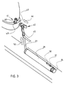
- the heel holding device shown in Figures 3 and 4 comprises an inextensible, all-round movable tension member 27 in the form of a band, which is fastened at one end to a tension spring 28 which is guided in a tube 29 fixed on the ski surface.
- This tube is located behind the boot heel on the ski surface and has at its end facing the boot a guide body 30 in the form of a plug fastened in the tube 29.
- This guide body 30 has a transverse slot 31 for the passage of the tension member 27.
- the end of the spring 28 facing away from the tension member 27 is fastened to an adjustable stop 32 which is guided displaceably in the tube 29 and has a threaded part 33 for screwing into the spring 28.
- a screw bolt 34 with head 35, which abuts the end of the tube 29, is screwed into an internal thread 36 of the stop 32.
- it has a pin 37 which extends through an elongated hole 38 in the tube 39.
- the expansion path of the spring 28 and thus the extension path of the tension member 27 is limited by the abutment of the front end 39 of the tension spring 28 on the guide body 30, whereby the requirement for a fixed stop for the pivoting movement of the Boot heel is met.
- the expansion path of the spring 28 can be changed by moving the stop 32. Thus, the resistance can be adjusted during the extension.
- the other end of the tension member 27 is attached to a bracket 40 which is designed in the manner of a pair of pliers and has a head 41 which comprises two grippers 42.
- a bracket 40 which is designed in the manner of a pair of pliers and has a head 41 which comprises two grippers 42.
- In one piece with the head 41 are two legs 43, through which a pin 44 is inserted, which bridges the gap between the two legs 43 and serves to fix the tension member 27, the end of which is wrapped around this pin and by means of a buckle 45 for adjusting the
- the pull-out path is adjustable.
- the clip 40 can be plugged in the direction of the arrow 46 onto a pin 47 which is fastened to the heel essentially perpendicular to the surface of the boot sole and has a cylindrical middle part 48 and two limiting flanges 49.
- the distance between the flanges 49 corresponds to the thickness of the head 41 of the clip 40, which is made of an elastic plastic and can be clipped with its gripper arms 42 onto the cylindrical part 48 of the pin 47, so that this clip against a certain resistance again Pin can be loosened. Since the clip fits exactly between the two flanges 49, this clip cannot be tilted. It can therefore only be pushed onto and removed from the pin axis perpendicular to the pin axis. As a result, the clamp cannot be released from the pin 47 when the boot heel is lifted, so that when the boot heel is lifted, the tension member 27 is pulled out of the tube 29 against the action of the spring 28.
- FIGS. 9 to 11 differs from that in FIG. 3 only in so far as the pin 47 is not arranged on the upper side of the protruding edge of the shoulder, but in a recess 51 in the stiffener heel, which makes it more pleasing Attachment of the pin 47 is reached.
- the pin 47 is held in the upper and lower boundary wall 51.1 and 51.2 and is at a certain distance from the vertical boundary wall 51.3.
- the distance between the boundary walls 51.1 and 51.2 running parallel to the sole surface corresponds to the thickness of the head 41 of the clamp 40, as a result of which these boundary walls take over the function of the flanges 49 in the embodiment according to FIG. 3 and prevent the clamp 40 from tilting relative to the pin 47.
- FIG. 10 shows the use of an all-around movable but inextensible tension member 27 which is fixed to the ski by means of a screw 27.1 and only serves to limit the stroke of the heel of the boot, the size of the pivoting angle of the boot sole relative to the ski being varied by changing the length of the tension member 27 by means of the buckle 45 is adjustable.
- 5 to 8 show two further embodiments for the design of the heel holding device, insofar as it relates to the design of the part to which the ski-fixed end of the tension member 27 is fastened and which serves to generate resistance when the tension member 27 is pulled out.
- a compression spring 53 is arranged in a ski-fixed housing 52, which is attached at one end to a pin 54 in the housing 52 and which has at its other end a T-shaped deflection body 55, the longitudinal bar of which 56 is inserted into the spring 53 and its cross bar 57 is guided in lateral longitudinal slots 58 of the housing 52.
- the tension member 27 is fixed at its ski-fixed end by means of a screw on the housing 52 or on the ski and is S-shaped guided on the one hand over the deflection body 57 and on the other hand over a further deflection body 59, which is formed by the delimitation of a slot 59.2 in the housing 52.
- the free end of the tension member 27 is attached to the ski boot in the same way as shown in FIGS. 3 and 9 to 11 and is therefore no longer shown in these figures. If the tension member 27 is now pulled, it is pulled out of the housing 52, the tension member pressing against the deflection body 57 during this movement and displacing it against the action of the spring 53.
- the displacement path can be limited by the slots 58, so that the heel of the boot is raised with increasing resistance up to a firm stop.
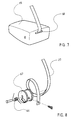
- FIGS. 7 and 8 show a further embodiment of the heel holding device.
- This comprises a reel spool 67 arranged in a housing 65 and loaded by a spring 66, which always tries to pull the tension member 27 through a slot 68 into the housing 65, the tension member 27 being reeled onto the reel spool 67, of which it is at one Raising the heel of the boot against the action of the spring 66 is unwound.
- FIG. 12 shows an embodiment of the heel holding device that is modified compared to FIGS. 5 and 6.
- the pulling member 27 is fastened at one end to the housing in a ski-fixed housing 52.1 and is guided in an S-shape over two deflecting bodies 55.1 and 59.1, the deflecting body 58.1 being the upper limit of a slot 59.3 from which the pulling member 27 leads out of the housing is.
- the deflecting body 55.1 is designed as a rotatably mounted roller which is rotatably mounted in a fork head 57.1 which is slidably guided in the housing in the longitudinal direction of the ski.
- the fork head 57.1 has a cylindrical extension 56.1 running in the longitudinal direction of the housing and thus in the longitudinal direction of the ski, onto which a compression spring 53 is attached.
- the other end of the compression spring is supported on an inner flange 68 of a hollow screw 70 formed with an outer flange 69, which can be screwed into a threaded bore 71 of the housing 52.1.
- This hollow screw 70 forms one with its inner flange 68 adjustable stop for the spring 53.
- the hollow screw 70 has a hollow cylindrical projection 72 projecting outwards from the outer flange 69, which is provided with an internal thread 73 into which a screw bolt 74 can be screwed and which engages in the interior of the spring 53.
- the screw bolt 74 is provided with a rotary knob 75, which is hollow and engages over the shoulder 72.
- the rotary knob 75 is used to adjust the screw bolt 74, whose end located within the housing 52.1 serves as a stop for the shoulder 56.1, which, depending on the screw-in depth of the screw bolt 74, creates a variable stop for limiting the pull-out path of the tension member 27.
- FIGS. 13 to 29 take into account the different requirements that are placed on such a heel-holding device during ski flying and landing to an even greater extent than was the case with the previously described embodiments.
- a clamp is used to fasten the tension member to the boot heel, as was described in its basic structure in connection with FIGS. 3 and 4.
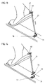
- the embodiment shown in Figures 13 and 14 comprises an inextensible, all-round movable tension member 27 in the form of a band, at one end of which a clip 40 is provided for attachment to a pin 47 on the heel of the boot, while the other end of the tension member 27 over one side the tension member carries protruding locking bolts 70 which can be locked in a clamping strip 71 fastened to the ski with two upwardly open locking grooves 72 which receive the projecting ends of the locking bolts in a form-fitting manner.
- the locking bolt 70 is in the locked position shown in FIG. 13, the tension member 27 restricting the swivel angle between the boot sole and the ski to the extent required for ski flight.
- the terminal strip 71 is preferably made of an elastically deformable plastic.
- a longer tension member 27.1 is provided, one end of which, as in the embodiment according to FIG. 13, is fastened to the pin 47 by means of the clamp 40, while the other end of the tension member 27.1 in the region of the sole support by means of a Screw 73 is attached to the ski.
- the intermediate area of the tension member 27.1 is guided around a deflection pin 74, which is pivotally mounted at one end at a ski-fixed point 75 and can be latched with its other end into a latching trap 76 arranged on the ski and can be released therefrom when a predetermined force is exceeded, as shown in Figure 16.
- FIGS. 17 and 18 basically corresponds in principle to the design according to FIGS. 13 and 14.
- a locking pin 70 is provided, which projects beyond the tension member 27 on both sides.
- This latching bolt can be latched into a latching groove 77 which is open at the bottom and positively accommodates the projecting ends of the latching bolt 70 and which is formed on the underside of the clamp 40.
- the other end of the tension member 27 is fixed to the ski by means of a screw 73.
- one end of the tension member 27 is fixed on the ski by means of a screw 73, while the other end, as shown in FIG. 4, is fixed on the clip 40.1 by means of a pin 44.
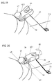
- the clamp despite the fixed connection of the tension member 27 on the ski and the clamp, releases the boot heel during the landing process enable, it is provided with a gap 78 which extends from the end which can be plugged onto the pin 47 to the recess 79 provided for the pin, which is formed between the grippers 42 of the clamp 40.1 and serves to receive the pin 47.
- this gap 78 the part of the clip which interacts with the pin 47, as can be seen in FIG.
- FIG. 19 shows the position of the tension member and the clamp during the flight phase
- FIG. 20 shows the state of this clamp that results when the clamp is released.
- the tension member is made in two parts, the two parts being designated 27.2 and 27.3.
- the two parts are connected to one another by a two-part connecting piece 81, which is designed in the manner of a push button.
- the two parts of the connecting piece are designated 81.1 and 81.2.
- Both parts are provided with eyelets 82 through which the ends of the parts 27.2 and 27.3 of the tension member can be fastened in an adjustable manner.
- the part 81.2 has a thickened head 83 which can be snapped into a corresponding locking recess 84 of the part 81.1. Since the two parts consist of an elastic plastic, the head 83 can be pulled out of the latching recess 84 under the action of an increased tensile force, as can be seen from FIG.
- FIG. 22 shows the same heel holding device as in FIG. 21, but in the open state, but a change in the ski binding is shown. While the heel-holding devices described so far are combined with a safety release binding according to FIGS. 1 and 2, FIG. 22 is intended to show the combination of the heel-holding device according to the invention with a hitherto common jump binding.
- a non-releasing front jaw 100 on which a cable tie, comprising a cable 101 with spring 102 resting on the heel, is guided to a conventional tensioner, not shown.
- the known deep-drawn hooks for the cable 101 provided on both sides are designated by 103.
- the tension member 27 is fastened to the ski and the boot heel in the same way as in the embodiment according to FIGS. 21 and 22.
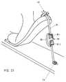
- the tension member is made in one piece, and the two parts 81.1 and 81.2 of the connecting piece 81 are fastened to the pulling element at a distance from one another, whereby in the closed state of the connecting piece 81 a loop 85 remains, by the length of which the pulling element is lengthened when the connecting piece 81 is loosened, as a result of which the boot heel is lifted higher is made possible on landing.
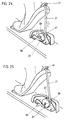
- one end of the tension member 27 is fixed to the heel of the boot by means of the clip 40 as in the previous embodiments, while the other end of the tension member 27 is rolled up on a reel spool 67, as shown for example in FIG and described in connection with this figure.
- the additional measure which is used in the embodiment according to FIGS. 24 and 25 compared to the embodiment according to FIGS. 7 and 8, serves to extend the tension member 27 during the transition from the flight phase to the landing, specifically over a defined swivel angle.
- This fixedly defined swivel angle which can be set for the flight phase, is ensured by a driver 86, which is provided on the reel spool 67 and a spring-loaded ski-fixed stop 87, on which there is contact when the take-up reel 67 rotates in the direction of the arrow 88, the driver 86 engages, as can be seen from FIG.
- the stop 87 is laterally deflected in the direction of the arrow 89, as a result of which the reel spool performs a further revolution and thereby a further piece of the Pull member 27 can release according to the circumference of the reel spool, which increases the pivot angle for the heel of the boot.
- FIGS. 26 to 29 show two variants of an embodiment which are similar to one another.
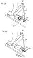
- a tension member 27 which can be fixed to the boot heel by means of a clip 40, is used, which is rolled up on a reel spool 67 in accordance with the embodiment according to FIGS. 24 and 25.
- the tension member in the embodiments according to FIGS. 26 to 29 is guided over a ski-fixed deflection device 90 which comprises a roller 92 which is rotatably mounted by means of a fitting part 91.
- a passage stop designated overall by 93, which consists of a U-shaped bracket, the base 94 of which is fastened to the fitting part or to the ski, while the upstanding legs 95 are elastic are resilient.
- a fixed thickening 96 is provided on the tension member 27, which is designed as a band, and which is located between the reel spool 67 and the passage barrier during the flight phase, in which the swivel angle of the boot is limited to a certain dimension 93 is located on which this thickening 96.1 is supported and thus limits the swivel angle of the heel of the boot. If an increased tractive force occurs during landing, the legs 95 of the passage blocker 93, as indicated by the arrow 97, are elastically pressed apart, so that the thickening can pass through the passage blocker 93, whereby the necessary extension of the tension member 27 occurs.
- FIGS. 28 and 29 differs from that according to FIGS. 26 and 27 only in that the thickening 96 has two slots 98 through which the tension band can be looped so that the thickening can be displaced on the tension member 27 designed as a band and is therefore adjustable.
Landscapes
- Footwear And Its Accessory, Manufacturing Method And Apparatuses (AREA)
- Crystals, And After-Treatments Of Crystals (AREA)
- Materials For Medical Uses (AREA)
- Binders And Loading Units For Sheaves (AREA)
- Package Frames And Binding Bands (AREA)
- Ropes Or Cables (AREA)
- Transition And Organic Metals Composition Catalysts For Addition Polymerization (AREA)
- Polishing Bodies And Polishing Tools (AREA)
- Prostheses (AREA)
- Polarising Elements (AREA)
- Photovoltaic Devices (AREA)
- Die Bonding (AREA)
- Amplifiers (AREA)
- Silicon Polymers (AREA)
- Pharmaceuticals Containing Other Organic And Inorganic Compounds (AREA)
- Acyclic And Carbocyclic Compounds In Medicinal Compositions (AREA)
- Regulating Braking Force (AREA)
- Magnetic Heads (AREA)
Applications Claiming Priority (2)
| Application Number | Priority Date | Filing Date | Title |
|---|---|---|---|
| DE4142434 | 1991-12-20 | ||
| DE4142434A DE4142434A1 (de) | 1991-12-20 | 1991-12-20 | Sicherheitsbindung |
Publications (3)
| Publication Number | Publication Date |
|---|---|
| EP0548806A2 true EP0548806A2 (fr) | 1993-06-30 |
| EP0548806A3 EP0548806A3 (fr) | 1993-07-14 |
| EP0548806B1 EP0548806B1 (fr) | 1999-03-10 |
Family
ID=6447789
Family Applications (2)
| Application Number | Title | Priority Date | Filing Date |
|---|---|---|---|
| EP92121492A Expired - Lifetime EP0553468B1 (fr) | 1991-12-20 | 1992-12-17 | Fixation de securité pour ski |
| EP92121491A Expired - Lifetime EP0548806B1 (fr) | 1991-12-20 | 1992-12-17 | Fixation de ski |
Family Applications Before (1)
| Application Number | Title | Priority Date | Filing Date |
|---|---|---|---|
| EP92121492A Expired - Lifetime EP0553468B1 (fr) | 1991-12-20 | 1992-12-17 | Fixation de securité pour ski |
Country Status (6)
| Country | Link |
|---|---|
| US (2) | US5310206A (fr) |
| EP (2) | EP0553468B1 (fr) |
| AT (2) | ATE177331T1 (fr) |
| DE (4) | DE4143411C2 (fr) |
| FI (2) | FI925791A7 (fr) |
| NO (2) | NO177889C (fr) |
Cited By (8)
| Publication number | Priority date | Publication date | Assignee | Title |
|---|---|---|---|---|
| WO1996020761A1 (fr) * | 1994-12-31 | 1996-07-11 | Adidas Ag | Chaussure pour ski de saut |
| EP1108453A2 (fr) | 1999-12-15 | 2001-06-20 | win.air Sportartikel GmbH | Fixation, spécialement pour le saut à ski |
| FR2804613A1 (fr) * | 2000-02-07 | 2001-08-10 | Salomon Sa | Dispositif de retenue d'une chaussure sur un engin de sport |
| WO2002064223A1 (fr) * | 2001-02-09 | 2002-08-22 | Salomon S.A. | Dispositif de retenue d"une chaussure sur un engin de sport |
| DE202010013473U1 (de) | 2010-09-21 | 2010-12-30 | Rass, Tom | Skibindung |
| DE102010026937A1 (de) | 2010-04-07 | 2011-10-13 | Win.Air Sportartikel Gmbh | Skischuh, Ski und Skibindung |
| EP2430933A1 (fr) | 2010-09-21 | 2012-03-21 | Tom Rass | Chaussure de saut à ski et système de fixation comprenant une chaussure de saut à ski et une fixation de ski |
| DE202018000659U1 (de) | 2018-02-09 | 2018-03-01 | Volkmar Rass | Skibindung |
Families Citing this family (18)
| Publication number | Priority date | Publication date | Assignee | Title |
|---|---|---|---|---|
| AT397351B (de) * | 1992-08-24 | 1994-03-25 | Aichholzer Franz | Kombination einer sicherheits-sprungschibindung mit einem sprungschuh |
| DE19506384C1 (de) * | 1995-02-23 | 1996-08-29 | Rottefella As | Bindung für das Skispringen oder den Tourenskilauf, insbesondre den Skilauf im Telemark-Stil |
| FI3090U1 (fi) * | 1996-12-10 | 1997-10-13 | Ilkka Tapani Tuomikoski | Mäkihyppyside |
| DE19703942C2 (de) * | 1997-02-03 | 1999-03-11 | Carl Franz | Schibindung |
| US5941553A (en) * | 1997-09-15 | 1999-08-24 | Korman; Nathan M. | Boot binding apparatus for a snowboard |
| US6168173B1 (en) | 1997-11-19 | 2001-01-02 | The Burton Corporation | Snowboard boot with binding interface |
| AT407837B (de) * | 1998-04-30 | 2001-06-25 | Aichholzer Franz | Sicherheitsbindung für einen sprungski |
| USD431275S (en) * | 1999-01-07 | 2000-09-26 | Blankenbaker Jr William R | Adjustable boot binding mount |
| AT412326B (de) * | 2002-10-22 | 2005-01-25 | Fischer Gmbh | Verbindung eines sprungskis mit einem skischuh |
| FR2850031B1 (fr) * | 2003-01-21 | 2006-08-11 | Salomon Sa | Fixation a energie deportee |
| FR2873044B1 (fr) * | 2004-07-13 | 2006-09-29 | Salomon Sa | Dispositif de fixation d'une chaussure a un article de sport avec systeme de rappel elastique separe |
| EP1791038A1 (fr) | 2005-11-24 | 2007-05-30 | Vaucher Manufacture Fleurier SA | Mouvement horloger |
| US7458598B2 (en) * | 2005-12-05 | 2008-12-02 | Jeffrey Giffin | Telemark binding with releasable riser plate assembly |
| EP2111900B1 (fr) * | 2008-04-25 | 2011-12-14 | Rottefella AS | Cartouche de ressort pour fixation de ski |
| DE102010040928A1 (de) * | 2010-09-16 | 2012-03-22 | Salewa Sport Ag | Gleitbrettbindung, insbesondere Tourenskibindung |
| EP2431081B1 (fr) | 2010-09-17 | 2014-11-05 | Österreichischer Skiverband | Guide de talon d'une fixation de ski |
| FI10002U1 (fi) * | 2012-06-18 | 2013-03-19 | Low Bind Oy | Mäkihyppyside |
| IT202100029006A1 (it) * | 2021-11-02 | 2023-05-02 | Atk Sports S R L | Porzione posteriore di attacco da sci alpinismo |
Family Cites Families (25)
| Publication number | Priority date | Publication date | Assignee | Title |
|---|---|---|---|---|
| CH179790A (de) * | 1934-11-29 | 1935-09-30 | Loepfe Ruegg Hans | An Skiern anzubringende Vorrichtung zum Anziehen der Skier gegen die Schuhhinterteile beim Skifahren. |
| AT148177B (de) * | 1935-02-27 | 1936-12-28 | Johann Brandauer | Sicherheitsvorrichtung für Skibindungen. |
| DE664562C (de) * | 1937-08-24 | 1938-08-30 | Erhard Kenk | Sprungskibindung |
| FR835768A (fr) * | 1938-03-26 | 1938-12-30 | Fixation de sécurité pour ski, à déchaussement automatique | |
| FR841929A (fr) * | 1938-08-09 | 1939-06-01 | Dispositif de sécurité perfectionnant la fixation élastique des skis sur les chaussures | |
| CH218104A (de) * | 1939-07-27 | 1941-11-30 | Christen Xaver | Sicherungsvorrichtung an Skiern mit Fersenzugbindungen. |
| US2396373A (en) * | 1941-01-02 | 1946-03-12 | Henrichsen Knut | Ski binding |
| US2685448A (en) * | 1950-11-21 | 1954-08-03 | Robert A Walker | Ski and binding therefor |
| US2789827A (en) * | 1955-05-16 | 1957-04-23 | Nicholas T Knauf | Heel release ski binding |
| US3825274A (en) * | 1970-11-17 | 1974-07-23 | Nat Recreation Ind | Ski binding with automatic boot-to-ski return |
| AT315695B (de) * | 1971-04-29 | 1974-06-10 | Riedel Tilo | Am Schuhvorderteil angreifendes fangriemenartiges Verbindungsglied |
| FR2179657B1 (fr) * | 1972-04-12 | 1976-10-29 | Salomon & Fils F | |
| US3941397A (en) * | 1974-06-17 | 1976-03-02 | Kidder Richard A | Ski device |
| FR2287928A1 (fr) * | 1974-10-15 | 1976-05-14 | Ramillon Rene | Accessoire de securite pour ski |
| DE2455147A1 (de) * | 1974-11-21 | 1976-05-26 | Dietrich Dipl Ing Lutz | Ski-sicherheitsfangeinrichtung |
| DE2526822A1 (de) * | 1975-06-16 | 1976-12-30 | Ver Baubeschlag Gretsch Co | Sicherheitsskibindung |
| CH570180A5 (en) * | 1975-08-21 | 1975-12-15 | Mezger Edgard | Ski safety line attached to skier - prevents loss of ski if separated from foot release bindings, does not cause injuries to skier |
| DE2846914C2 (de) * | 1978-10-27 | 1981-03-12 | Geze Gmbh, 7250 Leonberg | Sicherheits-Plattenskibindung |
| FR2497595B1 (fr) * | 1981-01-06 | 1985-05-17 | Salomon & Fils F | |
| FR2524812B1 (fr) * | 1982-04-08 | 1986-05-23 | Salomon Sa | Dispositif de fixation de securite pour le ski de fond |
| US4611822A (en) * | 1983-04-14 | 1986-09-16 | Bernhardson Gary E | Cross country ski binding |
| DE8405187U1 (de) * | 1984-02-21 | 1985-06-13 | Fedder, Hans-Werner, 5650 Solingen | Fangvorrichtung für Skier |
| CH667779A5 (de) * | 1985-10-04 | 1988-11-15 | Ueli Eser | Verbindung zwischen einem pedal fuer ein fahrrad und einem schuh. |
| FR2635014B1 (fr) * | 1988-08-05 | 1990-10-12 | Salomon Sa | Fixation de ski de fond a fermeture automatique |
| FR2638373B1 (fr) * | 1988-10-27 | 1991-01-25 | Salomon Sa | Fixation pour le maintien, sur un ski de fond, de l'avant d'une chaussure |
-
1991
- 1991-12-20 DE DE4143411A patent/DE4143411C2/de not_active Expired - Lifetime
- 1991-12-20 DE DE4143410A patent/DE4143410C2/de not_active Expired - Lifetime
-
1992
- 1992-12-17 NO NO924887A patent/NO177889C/no unknown
- 1992-12-17 AT AT92121491T patent/ATE177331T1/de active
- 1992-12-17 US US07/991,963 patent/US5310206A/en not_active Expired - Fee Related
- 1992-12-17 US US07/991,956 patent/US5366235A/en not_active Expired - Fee Related
- 1992-12-17 NO NO924888A patent/NO178327C/no unknown
- 1992-12-17 EP EP92121492A patent/EP0553468B1/fr not_active Expired - Lifetime
- 1992-12-17 DE DE59209647T patent/DE59209647D1/de not_active Expired - Lifetime
- 1992-12-17 DE DE59200539T patent/DE59200539D1/de not_active Expired - Lifetime
- 1992-12-17 AT AT92121492T patent/ATE111758T1/de not_active IP Right Cessation
- 1992-12-17 EP EP92121491A patent/EP0548806B1/fr not_active Expired - Lifetime
- 1992-12-18 FI FI925791A patent/FI925791A7/fi not_active Application Discontinuation
- 1992-12-18 FI FI925793A patent/FI925793A7/fi not_active Application Discontinuation
Cited By (12)
| Publication number | Priority date | Publication date | Assignee | Title |
|---|---|---|---|---|
| WO1996020761A1 (fr) * | 1994-12-31 | 1996-07-11 | Adidas Ag | Chaussure pour ski de saut |
| EP1108453A2 (fr) | 1999-12-15 | 2001-06-20 | win.air Sportartikel GmbH | Fixation, spécialement pour le saut à ski |
| DE19960571A1 (de) * | 1999-12-15 | 2001-07-12 | Win Air Sportartikel Gmbh | Skibindung, insbesondere für das Skispringen |
| DE19960571C2 (de) * | 1999-12-15 | 2002-02-28 | Win Air Sportartikel Gmbh | Skibindung, insbesondere für das Skispringen |
| EP1108453A3 (fr) * | 1999-12-15 | 2002-07-31 | win.air Sportartikel GmbH | Fixation, spécialement pour le saut à ski |
| FR2804613A1 (fr) * | 2000-02-07 | 2001-08-10 | Salomon Sa | Dispositif de retenue d'une chaussure sur un engin de sport |
| WO2002064223A1 (fr) * | 2001-02-09 | 2002-08-22 | Salomon S.A. | Dispositif de retenue d"une chaussure sur un engin de sport |
| DE102010026937A1 (de) | 2010-04-07 | 2011-10-13 | Win.Air Sportartikel Gmbh | Skischuh, Ski und Skibindung |
| DE102011016036A1 (de) | 2010-04-07 | 2012-01-05 | Win.Air Sportartikel Gmbh | Skischuh, Ski und Skibindung |
| DE202010013473U1 (de) | 2010-09-21 | 2010-12-30 | Rass, Tom | Skibindung |
| EP2430933A1 (fr) | 2010-09-21 | 2012-03-21 | Tom Rass | Chaussure de saut à ski et système de fixation comprenant une chaussure de saut à ski et une fixation de ski |
| DE202018000659U1 (de) | 2018-02-09 | 2018-03-01 | Volkmar Rass | Skibindung |
Also Published As
| Publication number | Publication date |
|---|---|
| FI925791A0 (fi) | 1992-12-18 |
| ATE111758T1 (de) | 1994-10-15 |
| DE4143411A1 (de) | 1993-07-15 |
| EP0548806B1 (fr) | 1999-03-10 |
| EP0553468A1 (fr) | 1993-08-04 |
| NO177889B (no) | 1995-09-04 |
| NO924887D0 (no) | 1992-12-17 |
| NO924888D0 (no) | 1992-12-17 |
| DE59200539D1 (de) | 1994-10-27 |
| FI925793A7 (fi) | 1993-06-21 |
| NO178327B (no) | 1995-11-27 |
| ATE177331T1 (de) | 1999-03-15 |
| EP0553468B1 (fr) | 1994-09-21 |
| DE59209647D1 (de) | 1999-04-15 |
| NO178327C (no) | 1996-03-06 |
| FI925793A0 (fi) | 1992-12-18 |
| DE4143410C2 (de) | 1995-06-29 |
| NO924887L (no) | 1993-06-21 |
| NO177889C (no) | 1995-12-13 |
| DE4143410A1 (de) | 1993-07-08 |
| NO924888L (no) | 1993-06-21 |
| DE4143411C2 (de) | 1995-06-29 |
| US5366235A (en) | 1994-11-22 |
| EP0548806A3 (fr) | 1993-07-14 |
| FI925791A7 (fi) | 1993-06-21 |
| US5310206A (en) | 1994-05-10 |
Similar Documents
| Publication | Publication Date | Title |
|---|---|---|
| EP0548806B1 (fr) | Fixation de ski | |
| DE2502956C2 (de) | Sohlenniederhalter für eine Ski-Sicherheitsbindung | |
| DE2346182C2 (de) | Skibindung | |
| DE2531466A1 (de) | Skibremsvorrichtung | |
| DE4142390C2 (de) | Sicherheitsbindung für Sprungski | |
| DE1478138C3 (de) | Fersenstrammer für Sicherheits-Skibindungen | |
| CH688023A5 (de) | Bindungseinrichtung zwischen einem Schuh und einem Sportgeraet | |
| DE3143974C2 (de) | Fersenhalter für eine Sicherheitsskibindung | |
| DE2639780C2 (fr) | ||
| DE2603009A1 (de) | Vorderbacken fuer eine sicherheitsskibindung | |
| EP4452430B1 (fr) | Système de fixation pour une fixation de ski de randonnée | |
| EP1795236B1 (fr) | Fixation de ski | |
| DE3013953A1 (de) | Schnallenverschluss fuer schuhe, insbesondere fuer ski- oder bergstiefel | |
| EP1108453B1 (fr) | Fixation, spécialement pour le saut à ski | |
| DE2348905A1 (de) | Ausloesebindung | |
| DE3210477A1 (de) | Skisicherheitsbindung | |
| EP0495192A1 (fr) | Fixation de ski pour ski de fond | |
| DE1578718B2 (de) | Auslösender Fersenhalter einer Skibindung | |
| DE4142434A1 (de) | Sicherheitsbindung | |
| DE60300131T2 (de) | Schliess- und Spannvorrichtung für Sportschuh oder für Bindungssystem für Gleitsportartikel | |
| DE19506384C1 (de) | Bindung für das Skispringen oder den Tourenskilauf, insbesondre den Skilauf im Telemark-Stil | |
| DE2629452A1 (de) | Schibindung | |
| DE2630770A1 (de) | Sicherheits-skibindung | |
| AT344558B (de) | Schibindung | |
| EP0114664A2 (fr) | Fixation de sécurité pour ski |
Legal Events
| Date | Code | Title | Description |
|---|---|---|---|
| PUAI | Public reference made under article 153(3) epc to a published international application that has entered the european phase |
Free format text: ORIGINAL CODE: 0009012 |
|
| PUAL | Search report despatched |
Free format text: ORIGINAL CODE: 0009013 |
|
| 17P | Request for examination filed |
Effective date: 19930429 |
|
| AK | Designated contracting states |
Kind code of ref document: A2 Designated state(s): AT DE |
|
| AK | Designated contracting states |
Kind code of ref document: A3 Designated state(s): AT DE |
|
| 17Q | First examination report despatched |
Effective date: 19931223 |
|
| GRAG | Despatch of communication of intention to grant |
Free format text: ORIGINAL CODE: EPIDOS AGRA |
|
| GRAG | Despatch of communication of intention to grant |
Free format text: ORIGINAL CODE: EPIDOS AGRA |
|
| GRAH | Despatch of communication of intention to grant a patent |
Free format text: ORIGINAL CODE: EPIDOS IGRA |
|
| GRAH | Despatch of communication of intention to grant a patent |
Free format text: ORIGINAL CODE: EPIDOS IGRA |
|
| GRAA | (expected) grant |
Free format text: ORIGINAL CODE: 0009210 |
|
| AK | Designated contracting states |
Kind code of ref document: B1 Designated state(s): AT DE |
|
| REF | Corresponds to: |
Ref document number: 177331 Country of ref document: AT Date of ref document: 19990315 Kind code of ref document: T |
|
| REF | Corresponds to: |
Ref document number: 59209647 Country of ref document: DE Date of ref document: 19990415 |
|
| RAP2 | Party data changed (patent owner data changed or rights of a patent transferred) |
Owner name: SILVRETTA SPORTARTIKEL GMBH |
|
| PLBE | No opposition filed within time limit |
Free format text: ORIGINAL CODE: 0009261 |
|
| STAA | Information on the status of an ep patent application or granted ep patent |
Free format text: STATUS: NO OPPOSITION FILED WITHIN TIME LIMIT |
|
| 26N | No opposition filed | ||
| PGFP | Annual fee paid to national office [announced via postgrant information from national office to epo] |
Ref country code: AT Payment date: 20101221 Year of fee payment: 19 |
|
| PGFP | Annual fee paid to national office [announced via postgrant information from national office to epo] |
Ref country code: DE Payment date: 20120131 Year of fee payment: 20 |
|
| REG | Reference to a national code |
Ref country code: DE Ref legal event code: R071 Ref document number: 59209647 Country of ref document: DE |
|
| REG | Reference to a national code |
Ref country code: DE Ref legal event code: R071 Ref document number: 59209647 Country of ref document: DE |
|
| REG | Reference to a national code |
Ref country code: AT Ref legal event code: MK07 Ref document number: 177331 Country of ref document: AT Kind code of ref document: T Effective date: 20121217 |