EP1108453A2 - Fixation, spécialement pour le saut à ski - Google Patents
Fixation, spécialement pour le saut à ski Download PDFInfo
- Publication number
- EP1108453A2 EP1108453A2 EP00124339A EP00124339A EP1108453A2 EP 1108453 A2 EP1108453 A2 EP 1108453A2 EP 00124339 A EP00124339 A EP 00124339A EP 00124339 A EP00124339 A EP 00124339A EP 1108453 A2 EP1108453 A2 EP 1108453A2
- Authority
- EP
- European Patent Office
- Prior art keywords
- ski
- tension member
- heel
- boot
- binding according
- Prior art date
- Legal status (The legal status is an assumption and is not a legal conclusion. Google has not performed a legal analysis and makes no representation as to the accuracy of the status listed.)
- Granted
Links
- 230000027455 binding Effects 0.000 title claims abstract description 27
- 238000009739 binding Methods 0.000 title claims abstract description 27
- 239000013013 elastic material Substances 0.000 claims description 2
- 230000009191 jumping Effects 0.000 claims description 2
- 230000006835 compression Effects 0.000 description 6
- 238000007906 compression Methods 0.000 description 6
- 230000008719 thickening Effects 0.000 description 6
- 238000013461 design Methods 0.000 description 4
- 230000004888 barrier function Effects 0.000 description 3
- 230000004048 modification Effects 0.000 description 3
- 238000012986 modification Methods 0.000 description 3
- 230000008859 change Effects 0.000 description 2
- 238000011161 development Methods 0.000 description 2
- 230000009471 action Effects 0.000 description 1
- 230000008901 benefit Effects 0.000 description 1
- 230000007423 decrease Effects 0.000 description 1
- 210000003746 feather Anatomy 0.000 description 1
- 238000003780 insertion Methods 0.000 description 1
- 230000037431 insertion Effects 0.000 description 1
- 210000003127 knee Anatomy 0.000 description 1
- 210000002414 leg Anatomy 0.000 description 1
- 238000000034 method Methods 0.000 description 1
- 230000008569 process Effects 0.000 description 1
- 230000037303 wrinkles Effects 0.000 description 1
Images


Classifications
-
- A—HUMAN NECESSITIES
- A63—SPORTS; GAMES; AMUSEMENTS
- A63C—SKATES; SKIS; ROLLER SKATES; DESIGN OR LAYOUT OF COURTS, RINKS OR THE LIKE
- A63C9/00—Ski bindings
- A63C9/08—Ski bindings yieldable or self-releasing in the event of an accident, i.e. safety bindings
- A63C9/083—Ski bindings yieldable or self-releasing in the event of an accident, i.e. safety bindings with loosenable cable strap
-
- A—HUMAN NECESSITIES
- A63—SPORTS; GAMES; AMUSEMENTS
- A63C—SKATES; SKIS; ROLLER SKATES; DESIGN OR LAYOUT OF COURTS, RINKS OR THE LIKE
- A63C9/00—Ski bindings
- A63C9/02—Non-self-releasing bindings with swivel sole-plate or swivel parts, i.e. Ellefsen-type
-
- A—HUMAN NECESSITIES
- A63—SPORTS; GAMES; AMUSEMENTS
- A63C—SKATES; SKIS; ROLLER SKATES; DESIGN OR LAYOUT OF COURTS, RINKS OR THE LIKE
- A63C9/00—Ski bindings
- A63C9/12—Non-self-releasing elastic heel-straps
-
- A—HUMAN NECESSITIES
- A63—SPORTS; GAMES; AMUSEMENTS
- A63C—SKATES; SKIS; ROLLER SKATES; DESIGN OR LAYOUT OF COURTS, RINKS OR THE LIKE
- A63C2201/00—Use of skates, skis, roller-skates, snowboards and courts
- A63C2201/04—Ski jumping
Definitions
- the invention relates to a ski binding, in particular for ski jumping, with a front sole holder and a heel holding device that can be lifted off the ski, which comprises a tension member that can be moved in all directions and that forms the heel of the boot connects to the ski and a lifting of the boot heel allows up to a predetermined amount, which Tension member at this height from a predetermined value one pulling force acting on the heel of the boot to a greater length extendable against the resistance of an additional device is.
- a ski binding of this type is known from EP 0 548 806 A2.
- the tension member is open a spring-loaded reel that wound up due to the tension is inclined to roll up the drawstring and thus shorten the distance between the boot heel and the ski.
- this is provided with a thickening that in another Pulling out the tension member pulled through a passage barrier must be what only with the expenditure of a increased strength is possible.
- the length up to the thickening corresponds the length that the ski jumper chooses to lift the heel of the boot off the ski during the flight phase can.
- the thickening forms the stop for lifting of the heel of the boot in the attitude.
- the object of the invention is a ski binding of the beginning explained type so that the boot heel up to a certain predetermined amount without counterforce or can be raised against a very low counterforce and after reaching this height, this is only exceeded overcome a predeterminable tensile force acting on the boot the arrangement should be such that when this force decreases, the originally set one Predeterminable amount of lifting of the boot heel again can be brought about.
- This task is based on a ski binding at the beginning specified type solved according to the invention in that the additional device from exceeding the predeterminable Height of the lifted boot heel a spring force exerts on the tension member, which is opposite to the tensile force.
- the decisive advantage of the invention Design is achievable, is that in one briefly exceeding the angle of attack of the sole of the boot compared to the ski the originally set distance of the Boot heel to the ski is automatically adjusted again, so that the ski jumper when he presented the stop again finds an increase in the angle between Boot sole and ski and thus a change in the location of the Ski jumpers against the ski and vice versa prevented. This means that the skis are stable and secure again Jump or flight of the ski jumper guaranteed.
- the additional device in the pulling direction the tension member adjustable against the ski.
- a preferred embodiment of the invention consists in that the additional device has a gas pressure spring with it Compression of essentially constant spring force includes and that the end of the boot heel facing away Tension member attacks on a part of the gas pressure spring, the other part is skifest. So with this configuration the tension member when the traction on the boot heel increases beyond a predeterminable value, on the gas pressure spring one, the entering extension of the tension member opposes an essentially constant resistance. This option to extend against the resistance the gas pressure spring is desirable for the telemark landing.
- the additional device can also comprise a helical spring, which is held ski-proof at one end and at the other End the tension member attacks. This will not the restoring force is kept constant as with the gas pressure spring, but this restoring force increases with increasing load the spring.
- the tension member can be designed as an inextensible hose, inside one connected to both hose ends Elastic band is arranged, which is tensioned when the tension member is stretched is and in the contracted state to a certainshrinking the hose leads.
- the trained as a hose Tension member is so when unused or in the downhill position of the ski jumper contracted, the inextensible tube wrinkles while when the tension member is pulled out up to the predetermined height the elastic in the hose stretched and the Tube is stretched so far that it inextensible the heel of the boot holds at the predetermined level. If the Hose connected to an additional device he can just like an otherwise usual inextensible tension member act on this additional device, whereby the additional Extension for the Telemark landing occurs.
- the tension member is inextensible in the direction of tension and essentially until the predetermined height is reached is unencumbered, because in this way Ski jumper after setting the predeterminable length of the Tension member ensures a firm stop when the paragraph lifted according to the preset length of the tension member is.
- Ski jumper due to the inextensibility of the tension member the ski jumper has a fixed end position at a predetermined Angle between the sole of the shoe and the ski so that it according to the given buoyancy in its flight posture can adjust. It essentially reaches this end position without counterforce, so no influence on the angle between boot sole and ski occurs, resulting in one of the ski binding leads to unaffected flight phase.
- An advantageous development of the invention consists in that the tension member is both arbitrarily detachable and at Occurrence of a value exceeding a predetermined value on Boot heel attacking traction the connection between Boot heel and ski releases.
- the force required for the release this connection is necessary can be set as high that they are not exceeded during the ski flight will, but in the event of a fall, there is a possibility that the ski jumper is completely free from the binding and free of the ski.
- the prerequisite for this is that the front sole holding device trips in the event of an overload.
- An advantageous embodiment for releasing the tension member from Boot heel consists of that associated with the boot heel End of the tension member a clip made of elastic Material, for example plastic, is provided one arranged on the boot, cylindrical, perpendicular to Boot sole surface standing cones and between two The flanges of the same can be snapped onto the pin axis in a positive-locking manner is.
- a clip made of elastic Material for example plastic
- Clamp in a plane perpendicular to the longitudinal axis of the pin have a gap that extends from that to the pin clip-on end up to that provided for the pin Extent extends and that one end of the The tension member skifest while the other end on the bracket is firmly arranged. Occur with this configuration strong Tipping forces on the bracket, so the bracket can deform due to the gap, making them no longer form-fitting held between the two flanges of the journal is and can therefore also be released from it if the direction of pull is not perpendicular to the pin axis.
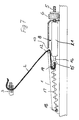
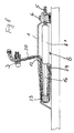
- FIG. 1 shows a heel holding device for ski bindings, in the case serving as a heel pad 1 an additional device shown in more detail in the further figures is provided, which is connected to a tension member 2 stands, which is provided with a bracket 3, the corresponding to Figures 2 to 4 on a not shown Bolt located in the heel area of the boot can be clipped on.
- the detailed design of the The clip and the pin on the ski boot can be found in EP 0 548 806 A2.
- From part 4 of the Housing 1 protrudes a threaded rod 5, which by means of a Knurled nut 6 is adjustable, which on the one hand on the housing part 4 and on the other hand on a support bracket 7, which is fixed with the housing part 4 is connected, is supported.
- the threaded rod 5 is, as for example from Figures 5 to 8 and 11 can be seen, connected to an additional device 8 or 9, which in Figures 5 to 8 as gas pressure spring 8.1 and in Figure 11 is designed as a coil spring 9.1.
- the additional device 8 or 9 is by means of knurled nut 6 and threaded rod 5 adjustable in the longitudinal direction of the ski.
- a ski boot 10 is in the Toe area by a front not shown Sole holder 11 held and the heel area is connected to the tension member 2 via the clamp 3, which according to FIGS. 5 to 7 via a roller 12 is guided into the interior of the housing 1, wherein a passage slot 13 the insertion of the tension member 2 into the housing 1 enables. That facing away from the boot heel or the clip 3
- the end of the tension member 2 is over another in the longitudinal direction of the ski Roller 14 slidably guided in the housing 1 guided and with the end 15 of a piston rod 16 of the gas pressure spring 8.1 connected.
- Figures 8 to 10 show a modification of the design according to FIGS. 5 to 7.
- the modification consists in that the return spring 17 by a differently designed tension member 20 was made redundant.
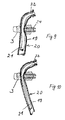
- the other tension member 20 consists, as can be seen from FIGS. 9 and 10, of a inextensible hose 19 and one inside the hose 19 arranged elastic band 21.
- the elastic band 21 and the hose 19 are at their ends by one Clip 22 firmly connected. I'm fully undressed State, which is shown in Figure 10, is the elastic 21 very much stretched and the inextensible hose 19 stretched.
- the hose 19 is shrunk like this Figure 8 and to a certain extent also from Figure 9.
- the elastic band 21 thus replaces the return spring 17.
- a Another modification is that the tension member 20 over a roller formed on the end piece 15 of the piston rod 16 23 is performed.
- the end of the heel facing away from the heel Tension member 20 is at a fixed point 24 within the housing 1 attached. If the tension member from the in FIG shown position attracted, then a via the roller 23 Compressive force on the piston rod 16 and thus on the gas pressure spring 8.1 exercised.
- Figure 8 shows the downhill position. In the flight phase is the outer tube 19 completely stretched. The additional length of the Tension member 20 in the Telemark landing is due to the compression the auxiliary device 8, i. by inserting the Piston rod 16 provided in the gas pressure of 8.1. At this tension member is the clamp 3 by means of a grub screw 24, as is the case with the embodiments according to the other figures.
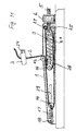
- FIG 11 shows an embodiment in which not only one modified guidance of the tension member 2 within the housing 1 is realized, but the additional device 9 is as Coil spring 9.1 executed.
- the tension member 2 in turn via the roller 12 in the housing 1 passed and over the roller 14, as in the embodiment according to Figures 5 to 7 out.
- the return spring 17 is provided.
- the change is now that the tension member after the roll 14 too a housing-fixed roller 25 is guided, from there on a Roller 26 is pulled, finally the end of the tension member is arranged at a point 27 fixed to the housing.
- the role 26 is rotatably mounted on a pressure piece 28, which on the Helical compression spring 9.1 acts.
- the guide slot 29 for the movable roller 14 is also good recognizable.
Landscapes
- Footwear And Its Accessory, Manufacturing Method And Apparatuses (AREA)
- Compositions Of Macromolecular Compounds (AREA)
- Fittings On The Vehicle Exterior For Carrying Loads, And Devices For Holding Or Mounting Articles (AREA)
Applications Claiming Priority (2)
| Application Number | Priority Date | Filing Date | Title |
|---|---|---|---|
| DE19960571A DE19960571C2 (de) | 1999-12-15 | 1999-12-15 | Skibindung, insbesondere für das Skispringen |
| DE19960571 | 1999-12-15 |
Publications (3)
| Publication Number | Publication Date |
|---|---|
| EP1108453A2 true EP1108453A2 (fr) | 2001-06-20 |
| EP1108453A3 EP1108453A3 (fr) | 2002-07-31 |
| EP1108453B1 EP1108453B1 (fr) | 2008-05-28 |
Family
ID=7932799
Family Applications (1)
| Application Number | Title | Priority Date | Filing Date |
|---|---|---|---|
| EP00124339A Expired - Lifetime EP1108453B1 (fr) | 1999-12-15 | 2000-11-17 | Fixation, spécialement pour le saut à ski |
Country Status (3)
| Country | Link |
|---|---|
| EP (1) | EP1108453B1 (fr) |
| AT (1) | ATE396774T1 (fr) |
| DE (2) | DE19960571C2 (fr) |
Cited By (2)
| Publication number | Priority date | Publication date | Assignee | Title |
|---|---|---|---|---|
| DE102010026937A1 (de) | 2010-04-07 | 2011-10-13 | Win.Air Sportartikel Gmbh | Skischuh, Ski und Skibindung |
| EP2431081A1 (fr) | 2010-09-17 | 2012-03-21 | Österreichischer Skiverband | Guide de talon d'une fixation de ski |
Families Citing this family (3)
| Publication number | Priority date | Publication date | Assignee | Title |
|---|---|---|---|---|
| DE202010013473U1 (de) | 2010-09-21 | 2010-12-30 | Rass, Tom | Skibindung |
| EP2430933B1 (fr) | 2010-09-21 | 2019-01-23 | Tom Rass | Chaussure de saut à ski et système de fixation comprenant une chaussure de saut à ski et une fixation de ski |
| DE202018000659U1 (de) | 2018-02-09 | 2018-03-01 | Volkmar Rass | Skibindung |
Citations (1)
| Publication number | Priority date | Publication date | Assignee | Title |
|---|---|---|---|---|
| EP0548806A2 (fr) | 1991-12-20 | 1993-06-30 | silvretta-sherpas Sportartikel GmbH | Fixation de ski |
Family Cites Families (2)
| Publication number | Priority date | Publication date | Assignee | Title |
|---|---|---|---|---|
| CH179790A (de) * | 1934-11-29 | 1935-09-30 | Loepfe Ruegg Hans | An Skiern anzubringende Vorrichtung zum Anziehen der Skier gegen die Schuhhinterteile beim Skifahren. |
| FR841929A (fr) * | 1938-08-09 | 1939-06-01 | Dispositif de sécurité perfectionnant la fixation élastique des skis sur les chaussures |
-
1999
- 1999-12-15 DE DE19960571A patent/DE19960571C2/de not_active Expired - Fee Related
-
2000
- 2000-11-17 AT AT00124339T patent/ATE396774T1/de not_active IP Right Cessation
- 2000-11-17 DE DE50015180T patent/DE50015180D1/de not_active Expired - Lifetime
- 2000-11-17 EP EP00124339A patent/EP1108453B1/fr not_active Expired - Lifetime
Patent Citations (1)
| Publication number | Priority date | Publication date | Assignee | Title |
|---|---|---|---|---|
| EP0548806A2 (fr) | 1991-12-20 | 1993-06-30 | silvretta-sherpas Sportartikel GmbH | Fixation de ski |
Cited By (3)
| Publication number | Priority date | Publication date | Assignee | Title |
|---|---|---|---|---|
| DE102010026937A1 (de) | 2010-04-07 | 2011-10-13 | Win.Air Sportartikel Gmbh | Skischuh, Ski und Skibindung |
| DE102011016036A1 (de) | 2010-04-07 | 2012-01-05 | Win.Air Sportartikel Gmbh | Skischuh, Ski und Skibindung |
| EP2431081A1 (fr) | 2010-09-17 | 2012-03-21 | Österreichischer Skiverband | Guide de talon d'une fixation de ski |
Also Published As
| Publication number | Publication date |
|---|---|
| EP1108453A3 (fr) | 2002-07-31 |
| DE19960571C2 (de) | 2002-02-28 |
| DE19960571A1 (de) | 2001-07-12 |
| ATE396774T1 (de) | 2008-06-15 |
| EP1108453B1 (fr) | 2008-05-28 |
| DE50015180D1 (de) | 2008-07-10 |
Similar Documents
| Publication | Publication Date | Title |
|---|---|---|
| EP0548806B1 (fr) | Fixation de ski | |
| EP2340876B1 (fr) | Chaussure de ski et système de fixation comprenant une chaussure de ski et une fixation de ski | |
| DE2700834C2 (de) | Sicherheitsskibindung | |
| DD268743A1 (de) | Klemme | |
| WO1985003643A1 (fr) | Fixation de ski de fond | |
| DE4010118A1 (de) | Bindungsvorrichtung eines paares von schuhen eines skilaeufers auf einem gleitbrett auf schnee | |
| EP3345659A1 (fr) | Talonnière automatique pour une fixation de ski | |
| EP1108453B1 (fr) | Fixation, spécialement pour le saut à ski | |
| DE4142390A1 (de) | Sicherheitsbindung fuer sprungski | |
| DE4142391A1 (de) | Skistiefel | |
| DE1478138A1 (de) | Fersenstrammer fuer Skibindungen | |
| CH644026A5 (de) | Sicherheitsskibindung fuer abfahrtsski. | |
| DE102013201723A1 (de) | Fersenhalter mit Schlitten zur Querauslösung und Hilfshebel | |
| EP1795236B1 (fr) | Fixation de ski | |
| DE2526822A1 (de) | Sicherheitsskibindung | |
| DE2608073A1 (de) | Fersenniederhalter fuer sicherheits- skibindungen | |
| DE2348905A1 (de) | Ausloesebindung | |
| DE60013335T2 (de) | Sicherheitsskibindung-Schuh-Kombination | |
| CH622953A5 (en) | Front safety jaw for ski bindings | |
| DE2621758C3 (de) | Sicherheits-Auslöseteil für Skibindungen | |
| DE69815558T2 (de) | Sicherheitsbindung an der Oberseite des Skistiefels | |
| DE4142434A1 (de) | Sicherheitsbindung | |
| DE1578836C3 (de) | Für Abfahrts- und Tourenlauf geeigneter Vorderbacken für Sicherheits-Skibindungen | |
| DE19651265C2 (de) | Sicherheits-Auslöseteil für Skibindungen | |
| DE2034355C3 (de) | Vorderbacken für Sicherheits-Skibindungen |
Legal Events
| Date | Code | Title | Description |
|---|---|---|---|
| PUAI | Public reference made under article 153(3) epc to a published international application that has entered the european phase |
Free format text: ORIGINAL CODE: 0009012 |
|
| AK | Designated contracting states |
Kind code of ref document: A2 Designated state(s): AT BE CH CY DE DK ES FI FR GB GR IE IT LI LU MC NL PT SE TR |
|
| AX | Request for extension of the european patent |
Free format text: AL;LT;LV;MK;RO;SI |
|
| PUAL | Search report despatched |
Free format text: ORIGINAL CODE: 0009013 |
|
| AK | Designated contracting states |
Kind code of ref document: A3 Designated state(s): AT BE CH CY DE DK ES FI FR GB GR IE IT LI LU MC NL PT SE TR |
|
| AX | Request for extension of the european patent |
Free format text: AL;LT;LV;MK;RO;SI |
|
| 17P | Request for examination filed |
Effective date: 20020823 |
|
| AKX | Designation fees paid |
Designated state(s): AT DE FI |
|
| GRAP | Despatch of communication of intention to grant a patent |
Free format text: ORIGINAL CODE: EPIDOSNIGR1 |
|
| GRAS | Grant fee paid |
Free format text: ORIGINAL CODE: EPIDOSNIGR3 |
|
| GRAA | (expected) grant |
Free format text: ORIGINAL CODE: 0009210 |
|
| AK | Designated contracting states |
Kind code of ref document: B1 Designated state(s): AT DE FI |
|
| REF | Corresponds to: |
Ref document number: 50015180 Country of ref document: DE Date of ref document: 20080710 Kind code of ref document: P |
|
| PG25 | Lapsed in a contracting state [announced via postgrant information from national office to epo] |
Ref country code: FI Free format text: LAPSE BECAUSE OF FAILURE TO SUBMIT A TRANSLATION OF THE DESCRIPTION OR TO PAY THE FEE WITHIN THE PRESCRIBED TIME-LIMIT Effective date: 20080528 |
|
| PLBE | No opposition filed within time limit |
Free format text: ORIGINAL CODE: 0009261 |
|
| STAA | Information on the status of an ep patent application or granted ep patent |
Free format text: STATUS: NO OPPOSITION FILED WITHIN TIME LIMIT |
|
| 26N | No opposition filed |
Effective date: 20090303 |
|
| PG25 | Lapsed in a contracting state [announced via postgrant information from national office to epo] |
Ref country code: AT Free format text: LAPSE BECAUSE OF NON-PAYMENT OF DUE FEES Effective date: 20081117 |
|
| PGFP | Annual fee paid to national office [announced via postgrant information from national office to epo] |
Ref country code: DE Payment date: 20101230 Year of fee payment: 11 |
|
| REG | Reference to a national code |
Ref country code: DE Ref legal event code: R119 Ref document number: 50015180 Country of ref document: DE Effective date: 20120601 |
|
| PG25 | Lapsed in a contracting state [announced via postgrant information from national office to epo] |
Ref country code: DE Free format text: LAPSE BECAUSE OF NON-PAYMENT OF DUE FEES Effective date: 20120601 |