EP0549001A2 - Verfahren und Gerät zur Steuerung des Motormomentes - Google Patents
Verfahren und Gerät zur Steuerung des Motormomentes Download PDFInfo
- Publication number
- EP0549001A2 EP0549001A2 EP92201263A EP92201263A EP0549001A2 EP 0549001 A2 EP0549001 A2 EP 0549001A2 EP 92201263 A EP92201263 A EP 92201263A EP 92201263 A EP92201263 A EP 92201263A EP 0549001 A2 EP0549001 A2 EP 0549001A2
- Authority
- EP
- European Patent Office
- Prior art keywords
- gear change
- engine speed
- torque management
- torque
- engine
- Prior art date
- Legal status (The legal status is an assumption and is not a legal conclusion. Google has not performed a legal analysis and makes no representation as to the accuracy of the status listed.)
- Granted
Links
- 238000000034 method Methods 0.000 title claims abstract description 27
- 230000005540 biological transmission Effects 0.000 claims abstract description 42
- 238000001514 detection method Methods 0.000 claims description 4
- 230000002401 inhibitory effect Effects 0.000 claims description 2
- LFHISGNCFUNFFM-UHFFFAOYSA-N chloropicrin Chemical compound [O-][N+](=O)C(Cl)(Cl)Cl LFHISGNCFUNFFM-UHFFFAOYSA-N 0.000 description 12
- 238000002474 experimental method Methods 0.000 description 4
- 230000000694 effects Effects 0.000 description 3
- 238000010586 diagram Methods 0.000 description 2
- 230000000977 initiatory effect Effects 0.000 description 2
- 230000003247 decreasing effect Effects 0.000 description 1
Images


Classifications
-
- B—PERFORMING OPERATIONS; TRANSPORTING
- B60—VEHICLES IN GENERAL
- B60W—CONJOINT CONTROL OF VEHICLE SUB-UNITS OF DIFFERENT TYPE OR DIFFERENT FUNCTION; CONTROL SYSTEMS SPECIALLY ADAPTED FOR HYBRID VEHICLES; ROAD VEHICLE DRIVE CONTROL SYSTEMS FOR PURPOSES NOT RELATED TO THE CONTROL OF A PARTICULAR SUB-UNIT
- B60W30/00—Purposes of road vehicle drive control systems not related to the control of a particular sub-unit, e.g. of systems using conjoint control of vehicle sub-units
- B60W30/18—Propelling the vehicle
-
- B—PERFORMING OPERATIONS; TRANSPORTING
- B60—VEHICLES IN GENERAL
- B60W—CONJOINT CONTROL OF VEHICLE SUB-UNITS OF DIFFERENT TYPE OR DIFFERENT FUNCTION; CONTROL SYSTEMS SPECIALLY ADAPTED FOR HYBRID VEHICLES; ROAD VEHICLE DRIVE CONTROL SYSTEMS FOR PURPOSES NOT RELATED TO THE CONTROL OF A PARTICULAR SUB-UNIT
- B60W10/00—Conjoint control of vehicle sub-units of different type or different function
- B60W10/04—Conjoint control of vehicle sub-units of different type or different function including control of propulsion units
-
- B—PERFORMING OPERATIONS; TRANSPORTING
- B60—VEHICLES IN GENERAL
- B60W—CONJOINT CONTROL OF VEHICLE SUB-UNITS OF DIFFERENT TYPE OR DIFFERENT FUNCTION; CONTROL SYSTEMS SPECIALLY ADAPTED FOR HYBRID VEHICLES; ROAD VEHICLE DRIVE CONTROL SYSTEMS FOR PURPOSES NOT RELATED TO THE CONTROL OF A PARTICULAR SUB-UNIT
- B60W10/00—Conjoint control of vehicle sub-units of different type or different function
- B60W10/10—Conjoint control of vehicle sub-units of different type or different function including control of change-speed gearings
- B60W10/11—Stepped gearings
-
- B—PERFORMING OPERATIONS; TRANSPORTING
- B60—VEHICLES IN GENERAL
- B60W—CONJOINT CONTROL OF VEHICLE SUB-UNITS OF DIFFERENT TYPE OR DIFFERENT FUNCTION; CONTROL SYSTEMS SPECIALLY ADAPTED FOR HYBRID VEHICLES; ROAD VEHICLE DRIVE CONTROL SYSTEMS FOR PURPOSES NOT RELATED TO THE CONTROL OF A PARTICULAR SUB-UNIT
- B60W30/00—Purposes of road vehicle drive control systems not related to the control of a particular sub-unit, e.g. of systems using conjoint control of vehicle sub-units
- B60W30/18—Propelling the vehicle
- B60W30/1819—Propulsion control with control means using analogue circuits, relays or mechanical links
-
- F—MECHANICAL ENGINEERING; LIGHTING; HEATING; WEAPONS; BLASTING
- F16—ENGINEERING ELEMENTS AND UNITS; GENERAL MEASURES FOR PRODUCING AND MAINTAINING EFFECTIVE FUNCTIONING OF MACHINES OR INSTALLATIONS; THERMAL INSULATION IN GENERAL
- F16H—GEARING
- F16H61/00—Control functions within control units of change-speed- or reversing-gearings for conveying rotary motion ; Control of exclusively fluid gearing, friction gearing, gearings with endless flexible members or other particular types of gearing
- F16H2061/0075—Control functions within control units of change-speed- or reversing-gearings for conveying rotary motion ; Control of exclusively fluid gearing, friction gearing, gearings with endless flexible members or other particular types of gearing characterised by a particular control method
- F16H2061/0096—Control functions within control units of change-speed- or reversing-gearings for conveying rotary motion ; Control of exclusively fluid gearing, friction gearing, gearings with endless flexible members or other particular types of gearing characterised by a particular control method using a parameter map
-
- F—MECHANICAL ENGINEERING; LIGHTING; HEATING; WEAPONS; BLASTING
- F16—ENGINEERING ELEMENTS AND UNITS; GENERAL MEASURES FOR PRODUCING AND MAINTAINING EFFECTIVE FUNCTIONING OF MACHINES OR INSTALLATIONS; THERMAL INSULATION IN GENERAL
- F16H—GEARING
- F16H61/00—Control functions within control units of change-speed- or reversing-gearings for conveying rotary motion ; Control of exclusively fluid gearing, friction gearing, gearings with endless flexible members or other particular types of gearing
- F16H61/04—Smoothing ratio shift
- F16H2061/0477—Smoothing ratio shift by suppression of excessive engine flare or turbine racing during shift transition
-
- F—MECHANICAL ENGINEERING; LIGHTING; HEATING; WEAPONS; BLASTING
- F16—ENGINEERING ELEMENTS AND UNITS; GENERAL MEASURES FOR PRODUCING AND MAINTAINING EFFECTIVE FUNCTIONING OF MACHINES OR INSTALLATIONS; THERMAL INSULATION IN GENERAL
- F16H—GEARING
- F16H63/00—Control outputs from the control unit to change-speed- or reversing-gearings for conveying rotary motion or to other devices than the final output mechanism
- F16H63/40—Control outputs from the control unit to change-speed- or reversing-gearings for conveying rotary motion or to other devices than the final output mechanism comprising signals other than signals for actuating the final output mechanisms
- F16H63/50—Signals to an engine or motor
- F16H63/502—Signals to an engine or motor for smoothing gear shifts
Definitions
- the present invention relates to a method and apparatus for controlling engine torque for use, for example, during a gear changing operation in a vehicle.
- EP-A-0,355,070 One example of a method of controlling engine torque in an automatic transmission is shown in EP-A-0,355,070, in which the engine torque is reduced during a period of the gear change.
- the start and end times of this control period are determined from mathematical formulae which are based on the engine speed at particular points in the gear change.
- a problem with this type of torque control is that the mathematical formulae do not give the best results over the whole range of gear changes.
- the present invention seeks to provide an improved method and apparatus for controlling the torque of an engine.
- values in a storage medium are preferably adapted to reduce torque during a gear change caused by disengagement and engagement of gears.
- an upshift start value for determining the start of torque management is obtained from a look-up table in the storage medium on the basis of throttle position, and torque management is started when the engine speed is less than the difference between a maximum engine speed occurring during the gear change and the upshift start value.
- the method comprises the step of starting torque management if the engine speed has not fallen below the difference between the maximum engine speed and the upshift start value within a predetermined start time.
- torque management can be made to start at the most appropriate time for the measured vehicle operating parameters, with a back-up facility of starting torque management in any event after a predetermined time if the engine speed does not reach the required value.
- the start time is measured from a predetermined time after commencement of the gear change.
- This predetermined time is usually around 20 to 35% of the total time for the gear change, and it has been found that this provides the best point from which to determine the start and end times for torque control.
- an upshift end value for determining the end of torque management is preferably obtained from a look-up table in the storage medium on the basis of a maximum engine speed occurring during the gear change, and torque management is ended when the engine speed is less than the upshift end value.
- the method may comprise the step of ending torque management if the engine speed has not fallen below the upshift end value within a predetermined end time.
- the end time is measured from a predetermined time after commencement of the torque management.
- a first reference engine speed for determining the start of torque management is preferably obtained from a look-up table in the storage medium on the basis of the transmission output speed at a predetermined point during the gear change, and torque management is started when the engine speed is greater than the first reference speed.
- a second reference engine speed for determining the end of torque management may be obtained from a look-up table in the storage medium on the basis of the transmission output speed at a predetermined point during the gear change, and torque management is ended when the engine speed is greater than the second reference speed.
- the method may comprise the step of ending torque management if the engine speed has not become greater than the second reference speed within a predetermined end time. This is a useful back-up facility if the engine speed never reaches the required speed.
- the method may also comprise the step of inhibiting the end of torque management until a predetermined period has elapsed from the start of torque management. This can ensure that torque management is not ended before the end of the gear change.
- the engine torque is returned gradually to the torque associated with the detected engine operating conditions when a gear change is not in progress. This can prevent a sudden, unwelcome, increase in engine torque after the gear change.
- upshift is used to denote a gear change from a lower gear to a higher gear (such as from first to second), while the term “downshift” is used to denote a gear change from a higher gear to a lower gear (such as from second to first).
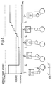
- a transmission control module 10 adapted to manage engine torque during gear changes is connected to an engine speed sensor (not shown) disposed to measure the speed of the engine 12, to an output speed sensor (not shown) disposed to measure the output speed of the transmission 14, and also to a throttle position sensor (not shown) adapted to measure the position of the throttle 16.
- An output 18 of the transmission control module 10 is connected to the engine control module 20 of the vehicle for supplying a replacement spark advance signal to the engine control module 20, as is described in further detail below.
- the engine control module 20 which is of any suitable form, is connected to the engine spark plugs through the distributor 22.
- Figure 1 also shows the principal components of the transmission control module 10. These include a detection unit 30 which is connected to the throttle position sensor and the transmission output speed sensor, and which is adapted to determine on the basis of the signals from these sensors whether it is appropriate to change gear and if so what the change should be. In use, the signals from these sensors are used to access a look-up table which gives an indication of the appropriate gear for the measured conditions, and therefore whether it is appropriate to change gear.
- a detection unit 30 which is connected to the throttle position sensor and the transmission output speed sensor, and which is adapted to determine on the basis of the signals from these sensors whether it is appropriate to change gear and if so what the change should be. In use, the signals from these sensors are used to access a look-up table which gives an indication of the appropriate gear for the measured conditions, and therefore whether it is appropriate to change gear.
- a processing unit 32 is connected to the output of the detection unit 30, and also to the signals from the transmission output speed sensor, the throttle position sensor and the engine speed sensor. In use, when the detection unit determines that a change in gears is necessary, it sends an enable signal to the processing unit 32. The processing unit 32 then determines the start and end times for torque management, by accessing a plurality of look-up tables (not shown) by means of one or more of the signals it receives from the various sensors, described in further detail below.
- Spark advance unit 36 is connected to an output of the processing unit 32 in such a manner that the spark advance unit 36 is enabled by an appropriate signal output on line 34 by the processing unit 32 during the determined start and end times for torque management.
- the spark advance unit 36 determines a replacement absolute spark advance from one or more look-up tables, which are described in further detail below, on the basis of the engine speed (NE) and the throttle position (THR), and sends the replacement spark advance to the engine control module 20 on output line 18. This process is repeated every 25 milliseconds, while it is enabled by the processing unit 32, thereby sending an updated spark advance to the engine control module 20 every 25 milliseconds.
- the replacement spark advance value sent to the ECM 20 is adapted to replace the spark advance calculated by the engine control module 20.
- the line 18 connecting the output of the spark advance unit 36 to the engine control module 20 may be a simple wire connection. Alternatively, it may be a serial connection, in which case, a signal indicative of the obtained spark advance is sent together with various identification codes and status codes, of conventional type.
- the transmission control module 10 sends a replacement spark advance signal to the engine control module so as to reduce the engine torque, and continues sending such a signal until a time t3, which is approximately at the end of the gear change.
- the transmission control module 10 ceases to send a replacement spark advance signal, and thereby enables the engine control module 20 to output the normal spark advance to the distributor 22. This increases the engine torque up to its normal value.
- Time t3 is usually no more than around 2 seconds after the change in the state of the solenoid (t0).
- the times for the start and end of torque management are determined from the engine speed (NE) measured at a time t1 after the change in the solenoid state.
- This time t1 is preferably around 0.3 to 0.5 seconds from t0, and normally around 20 to 35% of the total time taken for the gear change. It has been found that torque management can be significantly more effective if it is based on the engine speed after such a delay than at any other time in the gear change.
- the time t2 at which torque management starts is chosen as being either the time when the engine speed has decreased by more than a determined amount from the maximum engine speed measured after t1 or a predetermined time after the change in the state of the solenoid, whichever is the first to occur.
- torque management commences when: NE ⁇ NE max - K1(THR) or T t0 > C, where NE is the measured engine speed, NE max is the maximum engine speed measured after t1, K1(THR) is an amount determined as a function of throttle position, T t0 is time elapsed from t0 and C is a predetermined amount which is preferably around 1.2 to 1.6 seconds, depending of the type of the gear change.
- the amount K1(THR) is obtained from one of the look-up tables associated with the transmission control module 10 on the basis of throttle position, in other words of engine load.
- the look-up table is arranged so as to have a predetermined number of values for K1(THR) for each type of gear change such that one of these values is selected in dependence upon the throttle position and the type of the gear change.
- Each value in the look-up table is determined on the basis of experimental tests and is the value which gives the most comfortable gear change under the particular conditions.
- the value for K1(THR) is therefore generally not based on any particular mathematical formula.
- the transmission control module 10 sends a replacement spark advance signal to the engine control module 20, which is obtained from a three-dimensional look-up table on the basis of the throttle position (THR) and the engine speed (NE).
- the replacement spark advance signal is retarded relative to the spark advance which is used during normal running of the engine so that the torque of the engine is reduced during the gear change.
- the actual amount of retardation is determined on the basis of experimental tests and is intended to give the smoothest gear change.
- Torque management ends at time t3, either when the engine speed has fallen below a predetermined speed or when the time from the start of torque management exceeds a predetermined time, whichever is the first to occur.
- torque management ends when: NE ⁇ K2(NE max ) or T t2 > E
- K2(NE max ) is a value of engine speed which is obtained from a look-up table on the basis of the maximum engine speed NE max and the type of the gear change
- E is a predetermined time which in this embodiment is around one third of a second (usually around 15 to 20% of the total time taken for the gear change).
- K2(NE max ), as with K1(THR), is obtained from one of the look-up tables associated with the transmission control module 10 on the basis of the maximum engine speed NE max occurring during the gear change.
- the look-up table is arranged so as to have a predetermined number of values for K2(NE max ) for each type of gear change such that one of these values is selected in dependence upon the maximum engine speed NE max and the type of the gear change.
- the values for K2(NE max ) are determined, as with those for K1(THR) on the basis of experimental tests to give the most comfortable gear change.
- the start and end times for torque management during an upshift can thus be made to correspond to the best times on the basis of experimental tests, with the back-up facility of forcing commencement and ending of torque management at preset maximum times (C,E) should the conditions of steps 58 and 64 not be met.
- the routine commences at step 50 at which the tramsmission control module 10 sends a signal to the engine control module 20 representative of the change in the solenoid state, and hence of the commencement of the gear change.
- the engine control module 20 measures the change in engine speed ⁇ NE over a preset period. If the change is greater than a preset amount A, it determines at step 52 that the shift is a downshift, and if this is not the case, it determines that the shift is an upshift.
- the upshift routine 54 carried out by the transmission control module 10 first measures a delay t1 at step 56 and then proceeds to step 58 in which it obtains the value K1(THR) from the associated look-up table on the basis of the throttle position and determines if the engine speed is less than NE max by more than the value K1. If this is the case, the routine by-passes step 60 and moves to step 62.
- step 58 determines whether the time T t0 elapsed from t0 is greater than the predetermined amount C. If this test is positive, the routine proceeds to step 62, while if it is negative, the routine returns again to step 58.
- the routine obtains the absolute spark advance from a look-up table on the basis of the measured throttle position and engine speed. It then continues to steps 64 and 66 to determine if the end of the torque management period has been reached.
- the routine obtains the engine speed value K2(NE max ) from a look-up table on the basis of the maximum engine speed occurring after t1 and determines if the engine speed is below this value. If this is the case, the routine proceeds to step 68 to end torque management, and hence to return the spark advance to its normal value.
- step 66 determines whether the time T t2 elapsed from t2 has reached or exceeds the predetermined time E, and if so, proceeds to step 68 to end torque management. However, if the time T t2 is less than E, the routine returns to step 62.
- the transmission control module 10 determines that a lower gear should be engaged, it changes the state of the transmission solenoid, thereby initiating the downshift. As shown in Figure 4, this change occurs at time t0.
- a delay t4 is allowed to elapse before the transmission control module 10 begins its determination of the start and end times for torque management.
- This delay in a similar manner to the delay t1 for an upshift, is preferably around 20 to 25% of the total time taken for the gear change, and ensures that the transmission output speed used in determining the start and end times for torque management is appropriate for giving the most comfortable gear change.
- the transmission control module 10 commences torque management at time t5, when the engine speed becomes greater than a first reference engine speed, determined as a function of the transmission output speed measured repeatedly, preferably every 25 ms, after the delay t4.
- torque management starts when: NE > NE ref1 (OS), where NE ref1 (OS) is a first reference engine speed obtained from a look-up table on the basis of both the current transmission output speed (OS) and the type of gear change.
- the look-up table is arranged so as to have a predetermined number of values for NE ref1 (OS) for each type of gear change such that one of these values is selected every period, i.e.
- NE ref1 OS
- K1(THR) and K2(NE max ) K1(THR) and K2(NE max )
- the replacement absolute spark advance is obtained from a three dimensional look-up table on the basis of the throttle position (THR) and engine speed (NE).
- the three-dimensional look-up table is similar in lay-out to the look-up table for the upshift routine.
- the end of the period for torque management, at time t6, is determined when a preset minimum time T min has elapsed from the start of torque management at t5 and either the engine speed has increased to above a second reference speed NE ref2 (OS) or the time elapsed from time t5 has reached or is greater than a predetermined amount, whichever is the first to occur.
- OS second reference speed NE ref2
- NE ref2 (OS) is obtained every period from a look-up table on the basis of the current transmission output speed measured each period and the type of gear change. The values are determined by experimental tests and are adapted to provide the most comfortable gear change.
- the spark advance is gradually increased over a period from t6 to t7, which is preferably of the order of a fifth of a second, determined by experiment, and is intended to provide a smooth increase in torque.
- t6 to t7 which is preferably of the order of a fifth of a second, determined by experiment, and is intended to provide a smooth increase in torque.
- an alternative way of increasing the engine torque after torque management would be to increase the spark advance by a predetermined amount per unit time and to have a variable end time t7.
- the start and end times for torque management during a downshift can be made to correspond to the best times on the basis of experimental tests, with the back-up facility of ending of torque management at a preset maximum time (T max ) should the conditions of step 80 not be met. It has been found that it is not necessary to have a time limit for the start of the downshift if the engine speed never reaches the second reference speed NE ref2 since, if this condition is not met, it will not be necessary to carry out a gear change, and if no change is made, there is no risk of damaging the engine by causing it to run at too high a speed.
- step 52 of Figure 3 determines that the change in engine speed is greater than the preset value A, and hence that the gear change is a downshift, it proceeds to step 72 in which it provides the delay t4.
- the routine obtains at step 74 the first reference engine speed NE ref1 (OS) and determines whether the engine speed is greater than NE ref1 . If this is not the case, the routine returns to step 74 to find a new value for NE ref1 from the newly measured value of the output speed. However, if the test is positive, the routine proceeds to step 76 at which it obtains a replacement spark advance from the appropriate three-dimensional look-up table on the basis of the measured throttle position and engine speed. As with torque management during an upshift, the replacement spark advance values are retarded relative to the normal spark advance which is used during normal running of the engine so as to reduce the torque of the engine during the gear change. The amounts of retardation are determined by experiment as being those which give the most comfortable gear change.
- the routine determines if the time T t5 elapsed from t5 is greater than the minimum time T min , and if this is not the case it returns to step 76 again. However, if the minimum time has elapsed, the routine proceeds to steps 80 and 82 to determine whether torque management should end.
- step 80 the routine measures the current output speed, obtains the second reference speed NE ref2 (OS) from the appropriate look-up table on the basis of the current transmission output speed and then determines if the engine speed is greater than NE ref2 . If so, the routine by-passes step 82 to step 84 to end torque management. However, if the test is negative, the routine determines, at step 82, if the time T t5 elapsed from the start of torque management is greater than or equal to the maximum time T max and, if so, proceeds to step 84. However, if the maximum time T max has not been reached, the routine returns to step 76 on the basis that the gear change is still in progress.
- OS second reference speed NE ref2
- step 84 the spark advance is gradually increased over the preset time period from t6 to t7, and when this has been completed, the routine proceeds to step 86 at which torque management is ended.
- the effect of torque management during a downshift is shown schematically in Figure 6.
- the spark advance is shown as being around 400 before top dead centre.
- the spark advance is retarded from the normal position, so that ignition takes place around 200 after top dead centre in the example shown.
- the amount of retardation in other words the replacement spark advance, determined on the basis of the throttle position and engine speed, is reduced between times t8 and t6 due to a change in engine operating conditions. From time t6, the timing of ignition is gradually advanced back to the normal ignition time for the measured conditions.
- the three-dimensional tables used to determine the modified spark advance for each of the three described types of shift are different, although it would be possible to have a single table for all of the types of gear change.
Landscapes
- Engineering & Computer Science (AREA)
- Transportation (AREA)
- Mechanical Engineering (AREA)
- Chemical & Material Sciences (AREA)
- Combustion & Propulsion (AREA)
- Automation & Control Theory (AREA)
- Control Of Vehicle Engines Or Engines For Specific Uses (AREA)
- Combined Controls Of Internal Combustion Engines (AREA)
- Control Of Transmission Device (AREA)
- Electrical Control Of Ignition Timing (AREA)
Applications Claiming Priority (2)
| Application Number | Priority Date | Filing Date | Title |
|---|---|---|---|
| GB9127353 | 1991-12-24 | ||
| GB9127353A GB2262787B (en) | 1991-12-24 | 1991-12-24 | Method and apparatus for managing engine torque |
Publications (3)
| Publication Number | Publication Date |
|---|---|
| EP0549001A2 true EP0549001A2 (de) | 1993-06-30 |
| EP0549001A3 EP0549001A3 (en) | 1994-11-23 |
| EP0549001B1 EP0549001B1 (de) | 2000-01-19 |
Family
ID=10706800
Family Applications (1)
| Application Number | Title | Priority Date | Filing Date |
|---|---|---|---|
| EP92201263A Expired - Lifetime EP0549001B1 (de) | 1991-12-24 | 1992-05-06 | Verfahren und Gerät zur Steuerung des Motormomentes |
Country Status (5)
| Country | Link |
|---|---|
| US (1) | US5385516A (de) |
| EP (1) | EP0549001B1 (de) |
| JP (1) | JPH05223044A (de) |
| DE (1) | DE69230579T2 (de) |
| GB (1) | GB2262787B (de) |
Cited By (3)
| Publication number | Priority date | Publication date | Assignee | Title |
|---|---|---|---|---|
| FR2718191A1 (fr) * | 1994-04-05 | 1995-10-06 | Peugeot | Procédé et dispositif de suppression des oscillations longitudinales d'un véhicule automobile à moteur. |
| EP0805060A3 (de) * | 1996-04-30 | 1998-05-06 | Honda Giken Kogyo Kabushiki Kaisha | Steuerungssystem für Brennkraftmaschinen für Kraftfahrzeuge |
| EP1348590A3 (de) * | 2002-03-27 | 2007-03-28 | Caterpillar Inc. | Motor-und Getriebesteuerungssystem |
Families Citing this family (14)
| Publication number | Priority date | Publication date | Assignee | Title |
|---|---|---|---|---|
| JP3017900B2 (ja) * | 1993-03-15 | 2000-03-13 | アイシン・エィ・ダブリュ株式会社 | 車両用自動変速機の変速制御装置 |
| JP3404910B2 (ja) * | 1994-09-14 | 2003-05-12 | 日産自動車株式会社 | 無段変速機の変速ショック軽減装置 |
| US5779592A (en) * | 1995-07-27 | 1998-07-14 | Meritor Heavy Vehicle Systems, Llc | Four position switch for shift assist system |
| US5577474A (en) * | 1995-11-29 | 1996-11-26 | General Motors Corporation | Torque estimation for engine speed control |
| US5740045A (en) * | 1995-11-29 | 1998-04-14 | General Motors Corporation | Predictive spark controller |
| JP3599899B2 (ja) * | 1996-04-26 | 2004-12-08 | 本田技研工業株式会社 | 車両用内燃機関の出力トルク制御装置 |
| JPH09324663A (ja) * | 1996-06-03 | 1997-12-16 | Toyota Motor Corp | エンジンおよび自動変速機の一体制御装置 |
| US5738606A (en) | 1996-09-30 | 1998-04-14 | Cummins Engine Company, Inc. | Control system for regulating output torque of an internal combustion engine |
| US5803046A (en) * | 1996-10-31 | 1998-09-08 | General Motors Corporation | Ignition timing control |
| US6434466B1 (en) * | 1999-05-06 | 2002-08-13 | Ford Global Technologies, Inc. | System and method for determining engine torque for controlling a powertrain |
| JP4301232B2 (ja) * | 2005-10-26 | 2009-07-22 | トヨタ自動車株式会社 | 自動変速機の変速制御装置 |
| DE102009055833A1 (de) * | 2009-11-26 | 2011-06-01 | GM Global Technology Operations LLC, ( n. d. Ges. d. Staates Delaware ), Detroit | Verfahren zur Steuerung eines Schaltvorganges eines Automatikgetriebes |
| JP6604227B2 (ja) * | 2016-02-23 | 2019-11-13 | スズキ株式会社 | 出力制御装置 |
| CN112693326B (zh) * | 2021-01-19 | 2022-08-30 | 中国第一汽车股份有限公司 | 一种降扭量确定方法、装置、车辆及存储介质 |
Family Cites Families (17)
| Publication number | Priority date | Publication date | Assignee | Title |
|---|---|---|---|---|
| DE2842389C2 (de) * | 1978-09-29 | 1984-04-12 | Robert Bosch Gmbh, 7000 Stuttgart | Vorrichtung zur Einstellung des Drehmomentes einer Brennkraftmaschine |
| DE2848624A1 (de) * | 1978-11-09 | 1980-05-22 | Bosch Gmbh Robert | Verfahren zur beeinflussung einer brennkraftmaschine und vorrichtung zur durchfuehrung des verfahrens |
| JPS61271133A (ja) * | 1985-05-24 | 1986-12-01 | Toyota Motor Corp | 自動変速機の変速制御方法 |
| US4792902A (en) * | 1985-12-12 | 1988-12-20 | Ford Motor Company | Engine ignition timing for a clutch engagement control system |
| DE3632965C1 (de) * | 1986-09-27 | 1987-09-10 | Daimler Benz Ag | Anordnung zum Einstellen des Drehmomentes eines ein Gangwechselgetriebe antreibenden Verbrennungsmotores in Abhaengigkeit von bei Gangschaltungen aufschaltbaren gespeicherten Kennlinien |
| US5036728A (en) * | 1986-10-02 | 1991-08-06 | Mazda Motor Corporation | Engine control system for vehicle with automatic transmission |
| JPS644544A (en) * | 1987-06-26 | 1989-01-09 | Aisin Aw Co | Speed change control device for automobile |
| US5021956A (en) * | 1988-04-25 | 1991-06-04 | Mazda Motor Corporation | Control systems for vehicle engines coupled with automatic transmissions |
| US4968999A (en) * | 1988-04-29 | 1990-11-06 | Chrysler Corporation | Method of shift torque management for an electronic automatic transmission system |
| US5091854A (en) * | 1988-05-26 | 1992-02-25 | Mazda Motor Corporation | Control systems for vehicle engines coupled with automatic transmissions |
| FR2635597B1 (fr) * | 1988-08-18 | 1994-05-13 | Renault Regie Nale Usines | Procede de commande de modulation du couple d'un moteur thermique associe a une boite de vitesses automatique |
| US5012695A (en) * | 1988-10-07 | 1991-05-07 | Mazda Motor Corporation | Gear-shifting shock suppressing system for automatic transmission vehicle |
| JPH02264131A (ja) * | 1989-04-05 | 1990-10-26 | Mazda Motor Corp | 自動変速機を備えた車両の制御方法 |
| JP2510305B2 (ja) * | 1989-12-19 | 1996-06-26 | 日産自動車株式会社 | 自動変速機の作動油圧制御装置 |
| EP0518855B1 (de) * | 1990-03-06 | 1994-06-01 | Siemens Aktiengesellschaft | Steuerung für einen kraftfahrzeugantrieb |
| JP3011339B2 (ja) * | 1990-03-30 | 2000-02-21 | マツダ株式会社 | 自動変速機付きエンジンの出力低下制御装置 |
| US5129286A (en) * | 1991-06-27 | 1992-07-14 | Saturn Corporation | Engine torque management for engine speed flare suppression for clutch-to-clutch-upshifting |
-
1991
- 1991-12-24 GB GB9127353A patent/GB2262787B/en not_active Expired - Fee Related
-
1992
- 1992-05-06 EP EP92201263A patent/EP0549001B1/de not_active Expired - Lifetime
- 1992-05-06 DE DE69230579T patent/DE69230579T2/de not_active Expired - Fee Related
- 1992-05-20 JP JP4127560A patent/JPH05223044A/ja active Pending
- 1992-09-14 US US07/944,625 patent/US5385516A/en not_active Expired - Lifetime
Cited By (4)
| Publication number | Priority date | Publication date | Assignee | Title |
|---|---|---|---|---|
| FR2718191A1 (fr) * | 1994-04-05 | 1995-10-06 | Peugeot | Procédé et dispositif de suppression des oscillations longitudinales d'un véhicule automobile à moteur. |
| EP0805060A3 (de) * | 1996-04-30 | 1998-05-06 | Honda Giken Kogyo Kabushiki Kaisha | Steuerungssystem für Brennkraftmaschinen für Kraftfahrzeuge |
| US5839987A (en) * | 1996-04-30 | 1998-11-24 | Honda Giken Kogyo Kabushiki Kaisha | Control system for changing the time period at which torque is increased as a function of the time period at which a clutch is disengaged |
| EP1348590A3 (de) * | 2002-03-27 | 2007-03-28 | Caterpillar Inc. | Motor-und Getriebesteuerungssystem |
Also Published As
| Publication number | Publication date |
|---|---|
| JPH05223044A (ja) | 1993-08-31 |
| EP0549001B1 (de) | 2000-01-19 |
| GB9127353D0 (en) | 1992-02-19 |
| GB2262787B (en) | 1995-01-04 |
| GB2262787A (en) | 1993-06-30 |
| DE69230579T2 (de) | 2000-05-25 |
| US5385516A (en) | 1995-01-31 |
| DE69230579D1 (de) | 2000-02-24 |
| EP0549001A3 (en) | 1994-11-23 |
Similar Documents
| Publication | Publication Date | Title |
|---|---|---|
| EP0549001A2 (de) | Verfahren und Gerät zur Steuerung des Motormomentes | |
| US5103398A (en) | Shift control for slip control | |
| US5231582A (en) | Shifting control system for automotive automatic power transmission with enhanced variable shift pattern selection depending upon a resistance based upon vehicle acceleration and an engine parameter | |
| EP0475585B1 (de) | Verfahren und Einrichtung zur Glättung des Aufwärtsschaltvorganges in einem automatischen Getriebe | |
| KR900006593B1 (ko) | 자동변속기의 변속 제어장치 | |
| US5613920A (en) | Torque feedback shift control device and method | |
| US4370904A (en) | Method and apparatus for controlling the torque of an internal combustion engine | |
| US4731727A (en) | Intelligent optimum-gear indication system | |
| EP0352803B1 (de) | Gangschaltungssteuerung für Antriebsstrang | |
| US4439833A (en) | Method and apparatus for detecting the gear position of transmission | |
| US4800497A (en) | Clutch pressure control apparatus | |
| US5161432A (en) | Engine brake control system for automatic power transmission with variable response characteristics in shifting operational mode into engine braking range | |
| US7090616B2 (en) | Kick-down switching speed optimization for an automatic transmission of a motor vehicle | |
| JP3709787B2 (ja) | 変速時トルクダウン制御装置 | |
| US20030233185A1 (en) | Gear-shift control apparatus for automatic transmission and gear-shift control method | |
| EP2105634A2 (de) | Automatische Übertragungssteuerung und automatisches Übertragungssteuerungsverfahren | |
| US5995896A (en) | Methods and apparatus for controlling shifting processes in a vehicle transmission | |
| US5514051A (en) | Method and an arrangement for controlling an automatic transmission | |
| EP0355576B1 (de) | Ruck-Steuerungssystem für ein Antriebssystem | |
| US4825366A (en) | Lockup control system for automatic transmission | |
| EP0128394B1 (de) | Übersetzungsverhältnissteuerung eines stufenlosen Getriebes | |
| KR100491904B1 (ko) | 자동차의자동변속기의제어장치및제어방법 | |
| JPH08156652A (ja) | 車両の駆動トルク制御装置 | |
| US5559694A (en) | Device for reducing torque when shifting a transmission | |
| WO2007055795A1 (en) | Method of shifting gears in a work machine |
Legal Events
| Date | Code | Title | Description |
|---|---|---|---|
| PUAI | Public reference made under article 153(3) epc to a published international application that has entered the european phase |
Free format text: ORIGINAL CODE: 0009012 |
|
| AK | Designated contracting states |
Kind code of ref document: A2 Designated state(s): DE ES FR IT SE |
|
| RAP1 | Party data changed (applicant data changed or rights of an application transferred) |
Owner name: ACG FRANCE |
|
| PUAL | Search report despatched |
Free format text: ORIGINAL CODE: 0009013 |
|
| AK | Designated contracting states |
Kind code of ref document: A3 Designated state(s): DE ES FR IT SE |
|
| 17P | Request for examination filed |
Effective date: 19950523 |
|
| RAP1 | Party data changed (applicant data changed or rights of an application transferred) |
Owner name: DELPHI FRANCE AUTOMOTIVE SYSTEMS |
|
| 17Q | First examination report despatched |
Effective date: 19960212 |
|
| APAB | Appeal dossier modified |
Free format text: ORIGINAL CODE: EPIDOS NOAPE |
|
| RAP1 | Party data changed (applicant data changed or rights of an application transferred) |
Owner name: DELPHI FRANCE AUTOMOTIVE SYSTEMS |
|
| APBJ | Interlocutory revision of appeal recorded |
Free format text: ORIGINAL CODE: EPIDOS IRAPE |
|
| APAB | Appeal dossier modified |
Free format text: ORIGINAL CODE: EPIDOS NOAPE |
|
| APBJ | Interlocutory revision of appeal recorded |
Free format text: ORIGINAL CODE: EPIDOS IRAPE |
|
| APAD | Appeal reference recorded |
Free format text: ORIGINAL CODE: EPIDOS REFNE |
|
| APAB | Appeal dossier modified |
Free format text: ORIGINAL CODE: EPIDOS NOAPE |
|
| GRAG | Despatch of communication of intention to grant |
Free format text: ORIGINAL CODE: EPIDOS AGRA |
|
| GRAH | Despatch of communication of intention to grant a patent |
Free format text: ORIGINAL CODE: EPIDOS IGRA |
|
| GRAH | Despatch of communication of intention to grant a patent |
Free format text: ORIGINAL CODE: EPIDOS IGRA |
|
| GRAA | (expected) grant |
Free format text: ORIGINAL CODE: 0009210 |
|
| AK | Designated contracting states |
Kind code of ref document: B1 Designated state(s): DE ES FR IT SE |
|
| PG25 | Lapsed in a contracting state [announced via postgrant information from national office to epo] |
Ref country code: IT Free format text: LAPSE BECAUSE OF FAILURE TO SUBMIT A TRANSLATION OF THE DESCRIPTION OR TO PAY THE FEE WITHIN THE PRESCRIBED TIME-LIMIT;WARNING: LAPSES OF ITALIAN PATENTS WITH EFFECTIVE DATE BEFORE 2007 MAY HAVE OCCURRED AT ANY TIME BEFORE 2007. THE CORRECT EFFECTIVE DATE MAY BE DIFFERENT FROM THE ONE RECORDED. Effective date: 20000119 Ref country code: ES Free format text: THE PATENT HAS BEEN ANNULLED BY A DECISION OF A NATIONAL AUTHORITY Effective date: 20000119 Ref country code: SE Free format text: THE PATENT HAS BEEN ANNULLED BY A DECISION OF A NATIONAL AUTHORITY Effective date: 20000119 |
|
| REF | Corresponds to: |
Ref document number: 69230579 Country of ref document: DE Date of ref document: 20000224 |
|
| ET | Fr: translation filed | ||
| PGFP | Annual fee paid to national office [announced via postgrant information from national office to epo] |
Ref country code: FR Payment date: 20000515 Year of fee payment: 9 |
|
| PLBE | No opposition filed within time limit |
Free format text: ORIGINAL CODE: 0009261 |
|
| STAA | Information on the status of an ep patent application or granted ep patent |
Free format text: STATUS: NO OPPOSITION FILED WITHIN TIME LIMIT |
|
| 26N | No opposition filed | ||
| PGFP | Annual fee paid to national office [announced via postgrant information from national office to epo] |
Ref country code: DE Payment date: 20010626 Year of fee payment: 10 |
|
| PG25 | Lapsed in a contracting state [announced via postgrant information from national office to epo] |
Ref country code: FR Free format text: LAPSE BECAUSE OF NON-PAYMENT OF DUE FEES Effective date: 20020131 |
|
| PG25 | Lapsed in a contracting state [announced via postgrant information from national office to epo] |
Ref country code: DE Free format text: LAPSE BECAUSE OF NON-PAYMENT OF DUE FEES Effective date: 20021203 |
|
| APAH | Appeal reference modified |
Free format text: ORIGINAL CODE: EPIDOSCREFNO |