EP0549191A1 - Chambre de combustion pour turbine à gaz - Google Patents
Chambre de combustion pour turbine à gaz Download PDFInfo
- Publication number
- EP0549191A1 EP0549191A1 EP92311201A EP92311201A EP0549191A1 EP 0549191 A1 EP0549191 A1 EP 0549191A1 EP 92311201 A EP92311201 A EP 92311201A EP 92311201 A EP92311201 A EP 92311201A EP 0549191 A1 EP0549191 A1 EP 0549191A1
- Authority
- EP
- European Patent Office
- Prior art keywords
- fuel
- air
- premixer
- combustor
- gas turbine
- Prior art date
- Legal status (The legal status is an assumption and is not a legal conclusion. Google has not performed a legal analysis and makes no representation as to the accuracy of the status listed.)
- Granted
Links
Images

Classifications
-
- F—MECHANICAL ENGINEERING; LIGHTING; HEATING; WEAPONS; BLASTING
- F02—COMBUSTION ENGINES; HOT-GAS OR COMBUSTION-PRODUCT ENGINE PLANTS
- F02C—GAS-TURBINE PLANTS; AIR INTAKES FOR JET-PROPULSION PLANTS; CONTROLLING FUEL SUPPLY IN AIR-BREATHING JET-PROPULSION PLANTS
- F02C7/00—Features, components parts, details or accessories, not provided for in, or of interest apart form groups F02C1/00 - F02C6/00; Air intakes for jet-propulsion plants
- F02C7/22—Fuel supply systems
-
- F—MECHANICAL ENGINEERING; LIGHTING; HEATING; WEAPONS; BLASTING
- F23—COMBUSTION APPARATUS; COMBUSTION PROCESSES
- F23C—METHODS OR APPARATUS FOR COMBUSTION USING FLUID FUEL OR SOLID FUEL SUSPENDED IN A CARRIER GAS OR AIR
- F23C7/00—Combustion apparatus characterised by arrangements for air supply
Definitions
- This invention relates generally to minimizing NO x production in gas turbine combustors and more particularly concerns reducing NO x emissions by mixing a small portion of combustion air into the fuel lines upstream of the premixer section of the combustor.
- Hydrocarbons are widely used as fuels in gas turbine combustors. Because of its projected widespread availability, natural gas is an especially attractive fuel for stationary power generating systems. However, the emissions from the combustion of hydrocarbons lead to many environmental problems such as acid rain, ozone depletion and the "greenhouse” effect. Combustion by-products which pollute the atmosphere are required to be minimized as part of a growing concern for the quality of the environment. Oxides of nitrogen (NO x ) are particularly undesirable by-products.
- NO x is formed in part by reactions which occur between atmospheric nitrogen and oxygen atoms. Because of the high activation energy of these reactions, NO x formation is not significant at temperatures below approximately 1800 K to 1900 K. The requirement of high temperatures has led to water or steam injection for NO x control in conventional (non-premixed) combustors. In this approach, the injected water or steam absorbs heat, reduces the peak temperatures below the NO x -forming threshold, and so reduces NO x formation. However, this approach is expensive in terms of water or steam, can cause corrosion, and can increase carbon monoxide emission levels. Another common approach, injecting ammonia-based thermal deNO x into the exhaust stream, minimizes NO x , but this method is very expensive in terms of capital equipment and process ammonia.
- Lean premixed combustion of gaseous hydrocarbons is an attractive approach because it offers relatively clean combustion without the need for post-combustion treatment of the exhaust.
- lean premixed combustion is accomplished by premixing fuel and air just upstream of flame stabilization (in a section of the combustor called the premixer section) to form a mixture on the lean side of stoichiometric.
- the effect of premixing is to reduce and hopefully minimize the temperature at which the mixture burns, thus reducing NO x production which is temperature sensitive.
- the leaner the mixture the lower the combustion temperature will be.
- premixer sections of combustors used in industry typically fall short of completely mixing the gaseous fuel and air, thus resulting in higher levels of NO x .
- Efforts to improve the "mixedness" of fuel and air within the premixer by altering geometries and flow patterns have been attempted.
- practical designs are constrained by such factors as allowable pressure drop limits and space limitations.
- improvements in premixer designs some incomplete mixing generally exists. Incomplete mixing leads to nonuniformities and fluctuations in fuel concentration levels during lean premixed combustion. Such nonuniformities and fluctuations cause increased NO x production because NO x production increases nonlinearly with the fuel concentration.
- Head start partial premixing reduces NO x emission levels from a gas turbine combustor by mixing a small portion of air (typically around one to ten percent of the total combustion air supply) into the fuel line prior to injection into the combustor.
- the present invention preferably provides a gas turbine apparatus comprising a combustor having a premixer section for mixing fuel and air.
- a fuel line is connected to a first inlet for supplying fuel to the premixer section, and a source of air is connected to a second inlet of the premixer section.
- a means for injecting air into the fuel line upstream of said premixer section comprises means for diverting a small portion of air from the source of air to the fuel line.
- the present invention will be useful with any combustor that has imperfect mixing, regardless of its design. Furthermore, the present invention does not require expensive modifications of the combustor. The invention does not pose a safety problem because the head start partial premixing occurs relatively far upstream from the combustor and the fuel-air mixture in the fuel line is kept very rich (beyond the flammability limit) and therefore is not combustible.
- the present invention relies on the concept that mixing a small portion of air with fuel prior to injection into the premixer section of a combustor minimizes NO x production by reducing fluctuations and nonuniformities in the net mean fuel concentration level of the mixture of the premixer section.
- the theory behind this concept will be shown by comparing a typical premixed combustor with the combustor of the present invention.
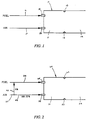
- FIG. 1 shows a schematic of a conventional combustor 10 for carrying out lean premixed combustion.
- the combustor 10 has a premixer section 11 where injected fuel and air are mixed and a combustion section 12 where the fuel-air mixture is burned.
- a flame stabilizer 13 separates the combustion and premixer sections.
- Two input ports 14 and 15 provide inlets to the premixer section 11. These ports can be configured in any well known manner.
- a fuel line 16 is connected to the second input port 15 for supplying fuel to the premixer section.
- a second line 17 is connected to the first input port 14. The second line 17 provides air to the premixer section 11 through the first input port.
- the maximum variance, in the net mean fuel concentration, C, of the mixture of the premixer section is given by:
- the variance is an indication of the magnitude of the fluctuations in fuel-air concentration.
- ⁇ is the fuel-air equivalence ratio.
- C will be approximately 0.05 and solving equation 1 gives
- the combustor 20 of the present invention is shown schematically. Like the combustor 10 of Figure 1, the combustor 20 has a premixer section 21 where injected fuel and air are mixed and a combustion section 22 where the fuel-air mixture is burned. A flame stabilizer 23 separates the combustion and premixer sections. Two input ports 24 and 25 provide inlets to the premixer section 21. A fuel line 26 is connected to the second input port 25 for supplying fuel to the premixer section. A second line 27 is connected to the first input port 24. The second line 27 is split into two branches 28 and 29.
- the first branch 28 delivers a small percentage, X, of the total air from line 27 to the fuel line 26, thereby causing the small portion of air to be mixed with the fuel prior to injection into the premixer section 21.
- the remainder of the air from the line 27 is directly delivered to the premixer section via the second branch 29 which is connected to the first input port 24.
- the amount of air injected into the fuel line is constrained in part by safety considerations. Ideally, as much air as possible is added because more air lowers the value of the fuel concentration, C2 through the second input port and the maximum variance possible is directly related to the value of C2.
- the fuel-air mixture in the fuel line 26 must be maintained very rich, beyond its flammability limit, or else combustion could occur in the fuel line; adding too much air to the fuel line could produce a flammable mixture.
- Other considerations include practical aspects of the system design such as required changes in fuel lines and fuel injectors and any additional air compression needed prior to injecting diverted air into the fuel line. Generally, an amount in the range of approximately one to ten percent of the total air volume is considered practical.
- the first branch 28 should be arranged to inject the small portion of air into the fuel line 26 at a point far upstream of the combustor 20. Not only does the distance from the combustor help prevent combustion in the fuel line, but the considerable distance the fuel-air mixture must travel through the fuel line results in thorough mixing.
- Figures 3-5 show the results of experiments carried out to test the concept of the present invention.
- a first experiment was conducted on a laboratory-scale device consisting of a premixer tube and a combustion tube joined together at respective ends.
- a center jet was coaxially disposed in the distal end of the premixer tube.
- a supply of air was provided to the premixer tube from a point upstream of the center jet.
- the juncture of the two tubes served as the flame stabilization location.
- the mean and fluctuating fuel concentrations were measured at the exit plane of the premixer and NO x emissions data were taken with a Beckman NO x analyzer located downstream in the combustion tube.
- Figure 3 shows a graph plotting the volumetric mean fuel concentration at the end of the premixer tube against the radial distance, z, from the longitudinal axis of the premixer tube, nondimensionalized by the diameter of the premixer tube, D p .
- the concentration profile where a fuel-air mixture was injected through the center jet was more uniform and closer to the ideal mixed case than the concentration profile where only fuel was injected through the center jet.
- Figure 4 shows a graph plotting the "unmixedness" level against the radial distance, z, from the longitudinal axis of the premixer tube, nondimensionalized by the diameter of the premixer tube, D p .
- the "unmixedness” level is defined as the variance of fuel-air concentration nondimensionalized by the value (1-C)C. (Note that the most unmixed case is such that the variance equals (1-C)C. Therefore, an unmixedness of 1 would correspond to the most unmixed case, and an unmixedness of 0 would correspond to the most mixed case.)
- the graph shows that the combustion run using head start partial premixing had a lower unmixedness level than combustion without head start partial premixing.
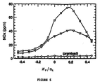
- Figure 5 plots NO x production in parts per million against the radial position of the probe, Zp, nondimensionalized by the diameter of the combustion tube, D c .
- the graph shows that using head start partial premixing provides a substantial improvement in NO x emissions.
- a second test procedure was conducted on a full-scale, single-can combustor.
- the fuel used was natural gas; the air-fuel mass ratio was about 1 (volume ratio of about 0.56), corresponding to a diversion of about two percent of the combustion air flow.
- the results showed that NO x emission reductions of about 20-25 percent from an initial level of 30 parts per million were possible.
Landscapes
- Engineering & Computer Science (AREA)
- Chemical & Material Sciences (AREA)
- Combustion & Propulsion (AREA)
- Mechanical Engineering (AREA)
- General Engineering & Computer Science (AREA)
Applications Claiming Priority (2)
| Application Number | Priority Date | Filing Date | Title |
|---|---|---|---|
| US811731 | 1985-12-20 | ||
| US07/811,731 US5247797A (en) | 1991-12-23 | 1991-12-23 | Head start partial premixing for reducing oxides of nitrogen emissions in gas turbine combustors |
Publications (2)
| Publication Number | Publication Date |
|---|---|
| EP0549191A1 true EP0549191A1 (fr) | 1993-06-30 |
| EP0549191B1 EP0549191B1 (fr) | 1997-11-12 |
Family
ID=25207403
Family Applications (1)
| Application Number | Title | Priority Date | Filing Date |
|---|---|---|---|
| EP92311201A Expired - Lifetime EP0549191B1 (fr) | 1991-12-23 | 1992-12-09 | Chambre de combustion pour turbine à gaz |
Country Status (7)
| Country | Link |
|---|---|
| US (1) | US5247797A (fr) |
| EP (1) | EP0549191B1 (fr) |
| JP (1) | JP3348111B2 (fr) |
| KR (1) | KR100304392B1 (fr) |
| CN (1) | CN1044516C (fr) |
| DE (1) | DE69223126T2 (fr) |
| NO (1) | NO302540B1 (fr) |
Cited By (2)
| Publication number | Priority date | Publication date | Assignee | Title |
|---|---|---|---|---|
| DE4412315A1 (de) * | 1994-04-11 | 1995-10-12 | Abb Management Ag | Verfahren und Vorrichtung zum Betreiben der Brennkammer einer Gasturbine |
| US11015808B2 (en) | 2011-12-13 | 2021-05-25 | General Electric Company | Aerodynamically enhanced premixer with purge slots for reduced emissions |
Families Citing this family (12)
| Publication number | Priority date | Publication date | Assignee | Title |
|---|---|---|---|---|
| US5518395A (en) * | 1993-04-30 | 1996-05-21 | General Electric Company | Entrainment fuel nozzle for partial premixing of gaseous fuel and air to reduce emissions |
| US5572862A (en) * | 1993-07-07 | 1996-11-12 | Mowill Rolf Jan | Convectively cooled, single stage, fully premixed fuel/air combustor for gas turbine engine modules |
| EP1199453A3 (fr) * | 1998-05-08 | 2003-01-22 | Mitsubishi Heavy Industries, Ltd. | Système de lavage des injecteurs de carburant d'une turbine à gaz |
| US6253538B1 (en) | 1999-09-27 | 2001-07-03 | Pratt & Whitney Canada Corp. | Variable premix-lean burn combustor |
| US6609380B2 (en) * | 2001-12-28 | 2003-08-26 | General Electric Company | Liquid fuel nozzle apparatus with passive protective purge |
| NO20070649L (no) * | 2007-02-05 | 2008-08-06 | Ntnu Technology Transfer As | Gassturbin |
| US8171716B2 (en) * | 2007-08-28 | 2012-05-08 | General Electric Company | System and method for fuel and air mixing in a gas turbine |
| US9140454B2 (en) * | 2009-01-23 | 2015-09-22 | General Electric Company | Bundled multi-tube nozzle for a turbomachine |
| US8539773B2 (en) * | 2009-02-04 | 2013-09-24 | General Electric Company | Premixed direct injection nozzle for highly reactive fuels |
| US9086018B2 (en) | 2010-04-23 | 2015-07-21 | Hamilton Sundstrand Corporation | Starting a gas turbine engine to maintain a dwelling speed after light-off |
| US9267690B2 (en) | 2012-05-29 | 2016-02-23 | General Electric Company | Turbomachine combustor nozzle including a monolithic nozzle component and method of forming the same |
| CN105157060A (zh) * | 2014-05-30 | 2015-12-16 | 胡晋青 | 一种透平燃烧室 |
Citations (1)
| Publication number | Priority date | Publication date | Assignee | Title |
|---|---|---|---|---|
| US4835962A (en) * | 1986-07-11 | 1989-06-06 | Avco Corporation | Fuel atomization apparatus for gas turbine engine |
Family Cites Families (7)
| Publication number | Priority date | Publication date | Assignee | Title |
|---|---|---|---|---|
| US3743258A (en) * | 1971-11-03 | 1973-07-03 | F Florentine | Fuel converter |
| DE2246625C3 (de) * | 1972-09-22 | 1982-02-18 | Robert Bosch Gmbh, 7000 Stuttgart | Kraftstoffzumeßanlage |
| US3940460A (en) * | 1974-02-14 | 1976-02-24 | Graybill Clinton L | Air-valve type carburetor |
| JPS5248732A (en) * | 1975-10-15 | 1977-04-19 | Toyota Motor Corp | Exhaust gas purification device of an internal combustion engine |
| US4090485A (en) * | 1977-03-28 | 1978-05-23 | Antonio LaCreta | Fuel systems for internal combustion engines |
| US4223615A (en) * | 1978-08-07 | 1980-09-23 | Kvb, Inc. | Low nox coal burner |
| US4320731A (en) * | 1980-01-04 | 1982-03-23 | Ford Motor Company | Carburetor air bleed control system |
-
1991
- 1991-12-23 US US07/811,731 patent/US5247797A/en not_active Expired - Fee Related
-
1992
- 1992-12-09 DE DE69223126T patent/DE69223126T2/de not_active Expired - Lifetime
- 1992-12-09 EP EP92311201A patent/EP0549191B1/fr not_active Expired - Lifetime
- 1992-12-18 JP JP33823792A patent/JP3348111B2/ja not_active Expired - Lifetime
- 1992-12-22 NO NO924975A patent/NO302540B1/no unknown
- 1992-12-22 KR KR1019920025071A patent/KR100304392B1/ko not_active Expired - Lifetime
- 1992-12-23 CN CN92115011A patent/CN1044516C/zh not_active Expired - Lifetime
Patent Citations (1)
| Publication number | Priority date | Publication date | Assignee | Title |
|---|---|---|---|---|
| US4835962A (en) * | 1986-07-11 | 1989-06-06 | Avco Corporation | Fuel atomization apparatus for gas turbine engine |
Non-Patent Citations (1)
| Title |
|---|
| PATENT ABSTRACTS OF JAPAN vol. 14, no. 198 (M-965)23 April 1990 & JP-A-02 040 417 ( CENTRAL RES. INST. OF ELECTRIC ) 9 February 1990 * |
Cited By (5)
| Publication number | Priority date | Publication date | Assignee | Title |
|---|---|---|---|---|
| DE4412315A1 (de) * | 1994-04-11 | 1995-10-12 | Abb Management Ag | Verfahren und Vorrichtung zum Betreiben der Brennkammer einer Gasturbine |
| DE4412315B4 (de) * | 1994-04-11 | 2005-12-15 | Alstom | Verfahren und Vorrichtung zum Betreiben der Brennkammer einer Gasturbine |
| US11015808B2 (en) | 2011-12-13 | 2021-05-25 | General Electric Company | Aerodynamically enhanced premixer with purge slots for reduced emissions |
| US11421884B2 (en) | 2011-12-13 | 2022-08-23 | General Electric Company | System for aerodynamically enhanced premixer for reduced emissions |
| US11421885B2 (en) | 2011-12-13 | 2022-08-23 | General Electric Company | System for aerodynamically enhanced premixer for reduced emissions |
Also Published As
| Publication number | Publication date |
|---|---|
| US5247797A (en) | 1993-09-28 |
| DE69223126T2 (de) | 1998-04-30 |
| NO302540B1 (no) | 1998-03-16 |
| NO924975L (no) | 1993-06-24 |
| DE69223126D1 (de) | 1997-12-18 |
| EP0549191B1 (fr) | 1997-11-12 |
| KR930013444A (ko) | 1993-07-21 |
| CN1044516C (zh) | 1999-08-04 |
| JPH05248261A (ja) | 1993-09-24 |
| JP3348111B2 (ja) | 2002-11-20 |
| CN1075189A (zh) | 1993-08-11 |
| NO924975D0 (no) | 1992-12-22 |
| KR100304392B1 (ko) | 2001-11-30 |
Similar Documents
| Publication | Publication Date | Title |
|---|---|---|
| US5247797A (en) | Head start partial premixing for reducing oxides of nitrogen emissions in gas turbine combustors | |
| US5308239A (en) | Method for reducing NOx production during air-fuel combustion processes | |
| US8292615B2 (en) | Single stage gaseous fuel burner with low NOx emissions | |
| AU748217B2 (en) | Fuel dilution methods and apparatus for NOx reduction | |
| US20100095649A1 (en) | Staged combustion systems and methods | |
| US5634784A (en) | Catalytic method | |
| EP0668469A2 (fr) | Procédé de combustion totalement non-stoechiométrique | |
| JPH03175211A (ja) | ガスタービン燃焼器、これを備えているガスタービン設備、及びこの燃焼方法 | |
| CN1443275A (zh) | 使燃料和稀释剂均匀以减少燃烧系统中释放物的方法和设备 | |
| KR102068037B1 (ko) | 예혼합 및 확산화염 형성을 통한 저질소산화물 연소장치 | |
| US20030101729A1 (en) | Retrofittable air assisted fuel injection method to control gaseous and acoustic emissions | |
| US20120159959A1 (en) | System and Method for Fuel and Air Mixing in a Gas Turbine | |
| US20040172949A1 (en) | Low emissions hydrogen blended pilot | |
| Avila et al. | Lean stability limits and exhaust emissions of ammonia-methane-air swirl flames at micro gas turbine relevant pressure | |
| US5216876A (en) | Method for reducing nitrogen oxide emissions from gas turbines | |
| US6658856B2 (en) | Hybrid lean premixing catalytic combustion system for gas turbines | |
| KR101733611B1 (ko) | 연소가스의 내부재순환 및 연료다단운전을 통한 초저질소산화물 연소장치 | |
| US5890442A (en) | Gas stabilized reburning for NOx control | |
| JP3139978B2 (ja) | ガスタービン燃焼器 | |
| US12038347B2 (en) | Method and apparatus for steady state and transient generation of NO2 and no for use with burner-based exhaust replication systems | |
| KR20260059559A (ko) | 연료 연소기, 연소 터빈 및 연소 방법 | |
| EP4731889A2 (fr) | Dispositif de combustion de combustible, turbine à combustion et procédé de combustion | |
| US12498117B2 (en) | Burner and combustion method for a burner | |
| SU1270491A1 (ru) | Способ сжигани газообразного топлива | |
| CN118273823A (zh) | 用于控制燃气涡轮发动机的顺序燃烧器的方法和燃气涡轮功率设备 |
Legal Events
| Date | Code | Title | Description |
|---|---|---|---|
| PUAI | Public reference made under article 153(3) epc to a published international application that has entered the european phase |
Free format text: ORIGINAL CODE: 0009012 |
|
| AK | Designated contracting states |
Kind code of ref document: A1 Designated state(s): CH DE FR GB IT LI NL SE |
|
| 17P | Request for examination filed |
Effective date: 19931129 |
|
| 17Q | First examination report despatched |
Effective date: 19940929 |
|
| GRAG | Despatch of communication of intention to grant |
Free format text: ORIGINAL CODE: EPIDOS AGRA |
|
| GRAH | Despatch of communication of intention to grant a patent |
Free format text: ORIGINAL CODE: EPIDOS IGRA |
|
| GRAH | Despatch of communication of intention to grant a patent |
Free format text: ORIGINAL CODE: EPIDOS IGRA |
|
| GRAA | (expected) grant |
Free format text: ORIGINAL CODE: 0009210 |
|
| AK | Designated contracting states |
Kind code of ref document: B1 Designated state(s): CH DE FR GB IT LI NL SE |
|
| PG25 | Lapsed in a contracting state [announced via postgrant information from national office to epo] |
Ref country code: NL Free format text: LAPSE BECAUSE OF FAILURE TO SUBMIT A TRANSLATION OF THE DESCRIPTION OR TO PAY THE FEE WITHIN THE PRESCRIBED TIME-LIMIT Effective date: 19971112 |
|
| REG | Reference to a national code |
Ref country code: CH Ref legal event code: NV Representative=s name: RITSCHER & SEIFERT PATENTANWAELTE VSP Ref country code: CH Ref legal event code: EP |
|
| ET | Fr: translation filed | ||
| REF | Corresponds to: |
Ref document number: 69223126 Country of ref document: DE Date of ref document: 19971218 |
|
| ITF | It: translation for a ep patent filed | ||
| NLV1 | Nl: lapsed or annulled due to failure to fulfill the requirements of art. 29p and 29m of the patents act | ||
| PLBE | No opposition filed within time limit |
Free format text: ORIGINAL CODE: 0009261 |
|
| 26N | No opposition filed | ||
| REG | Reference to a national code |
Ref country code: GB Ref legal event code: IF02 |
|
| PGFP | Annual fee paid to national office [announced via postgrant information from national office to epo] |
Ref country code: SE Payment date: 20021120 Year of fee payment: 11 |
|
| PG25 | Lapsed in a contracting state [announced via postgrant information from national office to epo] |
Ref country code: SE Free format text: LAPSE BECAUSE OF NON-PAYMENT OF DUE FEES Effective date: 20031210 |
|
| EUG | Se: european patent has lapsed | ||
| PGFP | Annual fee paid to national office [announced via postgrant information from national office to epo] |
Ref country code: IT Payment date: 20101228 Year of fee payment: 19 Ref country code: GB Payment date: 20101229 Year of fee payment: 19 |
|
| PGFP | Annual fee paid to national office [announced via postgrant information from national office to epo] |
Ref country code: CH Payment date: 20111227 Year of fee payment: 20 Ref country code: FR Payment date: 20120104 Year of fee payment: 20 |
|
| PGFP | Annual fee paid to national office [announced via postgrant information from national office to epo] |
Ref country code: DE Payment date: 20111229 Year of fee payment: 20 |
|
| REG | Reference to a national code |
Ref country code: DE Ref legal event code: R071 Ref document number: 69223126 Country of ref document: DE |
|
| REG | Reference to a national code |
Ref country code: DE Ref legal event code: R071 Ref document number: 69223126 Country of ref document: DE |
|
| REG | Reference to a national code |
Ref country code: CH Ref legal event code: PL |
|
| REG | Reference to a national code |
Ref country code: GB Ref legal event code: PE20 Expiry date: 20121208 |
|
| PG25 | Lapsed in a contracting state [announced via postgrant information from national office to epo] |
Ref country code: GB Free format text: LAPSE BECAUSE OF EXPIRATION OF PROTECTION Effective date: 20121208 |