EP0549332B1 - Dispositif de couplage optique - Google Patents
Dispositif de couplage optique Download PDFInfo
- Publication number
- EP0549332B1 EP0549332B1 EP92311717A EP92311717A EP0549332B1 EP 0549332 B1 EP0549332 B1 EP 0549332B1 EP 92311717 A EP92311717 A EP 92311717A EP 92311717 A EP92311717 A EP 92311717A EP 0549332 B1 EP0549332 B1 EP 0549332B1
- Authority
- EP
- European Patent Office
- Prior art keywords
- optical
- mixing rod
- fibres
- fibre
- connector
- Prior art date
- Legal status (The legal status is an assumption and is not a legal conclusion. Google has not performed a legal analysis and makes no representation as to the accuracy of the status listed.)
- Expired - Lifetime
Links
- 230000003287 optical effect Effects 0.000 title claims description 72
- 230000008878 coupling Effects 0.000 title claims description 39
- 238000010168 coupling process Methods 0.000 title claims description 39
- 238000005859 coupling reaction Methods 0.000 title claims description 39
- 239000000835 fiber Substances 0.000 claims description 47
- 238000005253 cladding Methods 0.000 claims description 12
- 239000000463 material Substances 0.000 claims description 11
- 239000013307 optical fiber Substances 0.000 claims description 10
- VYPSYNLAJGMNEJ-UHFFFAOYSA-N Silicium dioxide Chemical compound O=[Si]=O VYPSYNLAJGMNEJ-UHFFFAOYSA-N 0.000 claims description 4
- 239000005350 fused silica glass Substances 0.000 claims description 4
- 239000007788 liquid Substances 0.000 claims description 4
- 230000005540 biological transmission Effects 0.000 claims description 3
- 230000002093 peripheral effect Effects 0.000 claims description 3
- 239000004840 adhesive resin Substances 0.000 claims description 2
- 229920006223 adhesive resin Polymers 0.000 claims description 2
- 239000004417 polycarbonate Substances 0.000 claims description 2
- 229920000515 polycarbonate Polymers 0.000 claims description 2
- 238000009826 distribution Methods 0.000 description 10
- 230000007423 decrease Effects 0.000 description 2
- 239000011521 glass Substances 0.000 description 2
- 230000012447 hatching Effects 0.000 description 2
- 238000005286 illumination Methods 0.000 description 2
- 238000003780 insertion Methods 0.000 description 2
- 230000037431 insertion Effects 0.000 description 2
- 238000004519 manufacturing process Methods 0.000 description 2
- 238000012544 monitoring process Methods 0.000 description 2
- 239000004033 plastic Substances 0.000 description 2
- 239000004809 Teflon Substances 0.000 description 1
- 229920006362 Teflon® Polymers 0.000 description 1
- 230000009471 action Effects 0.000 description 1
- 230000006399 behavior Effects 0.000 description 1
- 230000008901 benefit Effects 0.000 description 1
- 238000005266 casting Methods 0.000 description 1
- 230000008859 change Effects 0.000 description 1
- 239000011248 coating agent Substances 0.000 description 1
- 238000000576 coating method Methods 0.000 description 1
- 230000008602 contraction Effects 0.000 description 1
- 230000000694 effects Effects 0.000 description 1
- -1 for example Substances 0.000 description 1
- PCHJSUWPFVWCPO-UHFFFAOYSA-N gold Chemical compound [Au] PCHJSUWPFVWCPO-UHFFFAOYSA-N 0.000 description 1
- 229910052737 gold Inorganic materials 0.000 description 1
- 239000010931 gold Substances 0.000 description 1
- 230000035515 penetration Effects 0.000 description 1
- 229920005989 resin Polymers 0.000 description 1
- 239000011347 resin Substances 0.000 description 1
- 230000000452 restraining effect Effects 0.000 description 1
- 229910052709 silver Inorganic materials 0.000 description 1
- 239000004332 silver Substances 0.000 description 1
Images







Classifications
-
- G—PHYSICS
- G02—OPTICS
- G02B—OPTICAL ELEMENTS, SYSTEMS OR APPARATUS
- G02B6/00—Light guides; Structural details of arrangements comprising light guides and other optical elements, e.g. couplings
- G02B6/24—Coupling light guides
- G02B6/26—Optical coupling means
- G02B6/28—Optical coupling means having data bus means, i.e. plural waveguides interconnected and providing an inherently bidirectional system by mixing and splitting signals
- G02B6/2804—Optical coupling means having data bus means, i.e. plural waveguides interconnected and providing an inherently bidirectional system by mixing and splitting signals forming multipart couplers without wavelength selective elements, e.g. "T" couplers, star couplers
- G02B6/2808—Optical coupling means having data bus means, i.e. plural waveguides interconnected and providing an inherently bidirectional system by mixing and splitting signals forming multipart couplers without wavelength selective elements, e.g. "T" couplers, star couplers using a mixing element which evenly distributes an input signal over a number of outputs
Definitions
- This invention relates to an optical coupling device for transmitting light emitted by a first optical fibre to each of a plurality of second optical fibres.
- Such a coupling device is disclosed in an article entitled POLYMERIC OPTICAL MIXING ROD COUPLER by L.L. Blyler and G.J. Grimes, of A.T. and T. Bell Laboratories, published in the proceedings of the 39th Electronic Conference, Houston, Texas, 1989, Pages 490 to 493.
- This known coupling device comprises a rectilinear mixing rod consisting of a Teflon (registered Trade Mark) tube filled with a transparent casting resin. A bundle of optical fibres is received in one end of the tube and a single large fibre is received in the other end thereof.
- the device may be operated as a light splitter or as a light combiner.
- a further known optical coupling device which is described in detail below, with reference to Figures 1 to 5 of the accompanying drawings, comprises first and second tubular connectors receiving the first and second optical fibres, respectively, with a cladded, optical end of each fibre exposed at a forward end of the respective connector, and an optical mixing rod interposed between the forward ends of the connectors, the mixing rod having optical ends optically interfaced with the optical ends of the first and second optical fibres, respectively, so as to distribute light emitted by the first optical fibre to illuminate the optical ends of the second optical fibres.
- the mixing rod of this further known optical coupling device is rectilinear.
- Such optical coupling devices which are known as star couplers, are used for example in automotive vehicles, in optical instruments, for industrial automation, or for monitoring sensors in a machine, where it is required that a single light signal be transmitted to a plurality of light sensitive devices.
- Patent specification US 4184740 discloses an optical coupling device in which the mixing rod comprises a curved central portion connecting first and second rectilinear portions of the mixing rod, each of these second portions terminating in a respective one of the optical ends of the mixing rod.
- the light proximate to the longitudinal axis of the mixing rod is constrained by the curvature thereof, so as to be reflected at different angles from the curving of the mixing rod to provide substantially uniform light distribution throughout the cross section of the emitting end of the mixing rod whereby the receiving fibres are substantially equally illuminated.
- the cross sectional shape of the mixing rod may be circular, or it may be other than circular, for example, in the case of a two fibre-to-two fibre coupling device.
- the current practice is to insert the fibres of a bundle into the connector one by one, or to confine the bundle of fibres by means of an O-ring, tape or tube, to ensure that the fibres extend parallel to the longitudinal axis of the connector when inserted thereinto.
- a tubular glass optical fibre connection is described in patent specification EP 0436112 into which fibres are fed individually. The internal configuration of the passage into which the fibres are fed holds them correctly juxtaposed until the glass tube is shrunk onto the fibres.
- An object of the invention is to provide an optical coupling device which allows simultaneous insertion of a plurality of fibres of a bundle into the device and overcomes the disadvantages discussed above.
- An optical coupling device according to the invention is defined in claim 1.
- an optical coupling device of the kind referred to above including a tubular connector formed with a series of internal peripheral, axially extending fibre guiding grooves opening into the forward end of the connector, each groove receiving a respective outer fibre of the bundle, these respective outer fibres retaining at least a central fibre of the bundle firmly into position in parallel relationship with said respective outer fibres.
- Each groove has a fibre lead-in rear portion tapering in width and depth towards a fibre lead-in mouth opening into the rear end of the connector and tapering forwardly thereof.
- the fibres of the bundle can accordingly be inserted simultaneously into the connector without the disadvantage mentioned above.
- the number of fibres may be seven, the number of grooves being six. In this case, a single fibre is held in alignment with the longitudinal axis of the connector.
- the bundle of fibres may however comprise a much greater number fibres, for example thirty two fibres. In this case, the outer fibres of the bundle, will hold a substantial number of inner fibres, in parallel relationship with the longitudinal access of the connector.
- the radius of curvature of the mixing rod may be between 20 mm and 50 mm.
- the mixing rod core diameter is preferably 4.52mm and for a nineteen fibre-to-nineteen fibre coupling device said diameter is preferably 5.07 mm.
- the mixing rod may be of non-circular cross section where, for example, the coupling device is a two fibre-to-two fibre device.
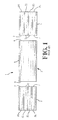
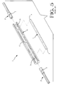
- a known optical star coupling device 1 for guiding light from a single optical fibre of a plurality thereof, into a plurality of optical fibres will now be described from a theoretical point of view with reference to Figures 1 to 4.
- the coupling device 1 comprises a pair of optical fibre connectors 2 and 4, respectively, each receiving and mechanically confining a bundle F of optical fibres, F1 to F7, respectively, and a rectilinear constant cross section optical mixing rod 5 provided with cladding 6.
- the rod 5 is of circular cross-section according to the present example, and may be described as an optical wave guide. Such a wave guide could, however, be of rectangular cross-section.
- Each connector 2 and 4 is in the form of a simple tubular ferrule, which is smooth walled both internally and externally, and which, in this example is of circular cross-section.
- the fibre F5 in the connector 4 is light emissive, as indicated by hatching
- the light from the fibre F5 is guided by the mixing rod 5 so as to illuminate the ends of all of the fibres F1 to F7 in the connector 2, also as indicated by hatching.
- a selected fibre in the connector 2 could be made emissive so as to illuminate the ends 7 of all the fibres in the connector 4.
- Such a coupling device is used for example in an optical control system, for example in a motor vehicle, an optical instrument, for industrial automation, or for monitoring sensors in a machine; where it is required that a single light signal be transmitted to a plurality of light sensitive devices.
- the connectors 2 and 4 with bundles of fibres F received therein are accommodated in a housing 10 having a central bore 12 receiving the rod 5, each connector 2 and 4 being snugly received in a respective end portion 14 of the bore 12.
- a disadvantage of an internally smooth walled connector is that since the fibres F1 to F7 have a plastic memory and thus tend, when de-reeled, to bend so as to return towards their reeled configurations, the longitudinal axes of the fibres, do not, if the fibres of a bundle are inserted together into the connector, align themselves with the longitudinal axis of the connector.
- the fibres tend to twist from straight positions SP thereof so as to tilt with respect to the longitudinal axis Z-Z of the bundle, so that the longitudinal axis Y-Y of a twisted fibre is displaced from the axis Z-Z by an angle t of tilt, whereby the optical end faces 7 of the fibres are displaced, with respect to the straight positions SP.
- the current practice is to insert the fibres of a bundle into the connector one by one, or to confine the bundle of fibres by means of an Oring, tape or tube to ensure that the fibres extend parallel to the longitudinal axis of the connector when inserted thereinto.
- such a coupling device can comprise a multiplicity of fibres in each bundle.
- the distribution of the light achieved by the mixing rod should, as far as possible, be equal. Uniformity defined as the difference between the highest and the lowest power measured at all the input ports and output ports of the coupling device, should, therefore, be as low as possible.
- the low order modes LOM that is to say the light beams proximate to the longitudinal axis X-X of the rod 5 propagate, as shown in Figure 6, in the direction of the axis X-X, although the high order modes HOM, that is to say the light beams more remote from the axis X-X are reflected by the cladding 6 of the rod 5 and are thus better distributed than the low order modes LOM.
- the power measured at the middle receiving fibre F7 is accordingly substantially the greater, whereas the other receiving fibres F1 to F6, are, consequentially, illuminated to a lesser extent. Said uniformity is also insufficient where one of the fibres F1 to F6 is emissive.
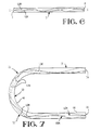
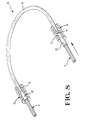
- an optical star coupling device 16 for the same purpose as the known device 1, and also, being, by way of example, a seven fibre to seven fibre coupling device, comprises a pair of housings 18, a pair of connectors 20 receiving a bundle of optical fibres F and an optical mixing rod 22 of U-shaped configuration.
- each housing 18, which is of circular crosssection, has a central axial bore 24 having a rear portion 26 of constant cross-section, opening into a connector receiving face 28 of the housing 18 and a forward portion 30 of smaller cross-section than the rear portion 26, opening into a mixing rod receiving face 32 of the housing 18.
- One of the connectors 20 extends partially into the bore portion 24, with an end face 33 of the connector 20 in spaced relationship with optical an end face 34 of one end portion of the mixing rod 22 the end face 34 may, as described below, be either the emissive, or the receiving end face of the rod 22.
- the space between the faces 33 and 34 constitutes the interface 35 between them as shown at the bottom of Figure 8 and at the top of Figure 11. The optimum situation is when the faces 33 and 34 are in contact, that is to say when there is no space between them as shown at the top of Figure 8 and at the bottom of Figure 11.
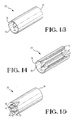
- each connector 20 which is in the form of an overall circular cross-section hollow tube, has a fibre bundle receiving rear end 36 having an outwardly flared, internally smooth, circular cross-section, frusto-conical fibre lead-in mouth 38.
- the grooves 40 are constantly spaced from each other about the longitudinal axis of the connector 20 in a circular array and are separated from one another by flat topped axial splines 42.
- Each groove 40 has a fibre lead in rear end portion 44 which tapers both in width and in depth toward the mouth 38 and terminates at the forward end thereof.
- a bundle F of seven fibres F1 to F7 can readily be inserted into the connector 20 from its fibre receiving end 36, guided by the walls of the frusto-conical mouth 38 so that each of the outer fibres F1 to F6 of the bundle F, guided by the portion 44 of the respective groove 40 is received in the remainder of the groove 40, with the leading end of each fibre protruding slightly beyond the forward end 33 of the connector 20.
- the outer fibres F1 to F6 hold the centre fibre F7 firmly in its position along the central longitudinal axis of the connector 20, as best seen in Figures 17 and 18.
- the bundle of fibres F is bonded into the connector 20 by means of a bonding material which is preferably index matched with the cladding material of the fibres..
- the leading ends of the fibres are then polished flat to provide optical ends 7 and so as to be level with the forward end 33 of the connector 20, when the bonding material has cured.
- the diameter of the core of each fibre is, in the present example, typically 0.98mm, the fibre bundle diameter being 3mm, overall.
- the optical mixing rod 22 may be a large cross-section polycarbonate optical fibre having a cladding 46 ( Figures 9 and 10); having refractive indices matched to the fibres 1 to 7.
- the core of the rod 22 may be of pure fused silica, the cladding being fused silica.
- the difference in refractive index between the core of the rod 22 and the cladding thereof must result in an N.A. (numerical aperture) matching to the fibres F1 to F7 or the rod 22 must be coated with a light reflective material, for example, silver or gold, which materials are ideal for the 660nm wavelength range.
- the N.A. number of numerical aperture
- the housings 18, are also preferably of a low refractive index material, the difference in the refractive index between the housing and the core of the rod 22, resulting in an N.A. of 0.50.
- the housing 18 could have a reflective surface coating over the extent of the bore portion 30.
- a refractive index matching liquid for the 660nm wavelength may be disposed in the interface 35 between the end faces 33 and 34, although in this case the connectors should be provided with spring loaded adaptors restraining, in known fashion, their withdrawal from the housings.
- Said matching liquid has the advantage that it is received in the interstices between the fibres, which provide a reservoir allowing for thermal expansion and contraction of the connectors and the housing, the penetration of the matching liquid between the fibres being limited by capillary action.
- an ultra violet ray curable adhesive resin with the correct refractive index and transmission at 660nm could be substituted for the index matching material, the housing being transparent.
- the total active diameter of the fibres should be equal to that of the mixing rod, as far as possible, at the interface 35 between the end faces 33 and 34.
- the mixing rod 22 is so shaped that the low order modes LOM are forced to propagate other than in the axial direction.
- the distribution of the high order modes HOM is also improved. These improvements are achieved by virtue of the curvature of the mixing rod 22.
- the low order modes LOM propagate from the notional light receiving optical end of the rod 22, which end is referenced 34 in Figure 7, in a direction parallel to the central axis of the rod 22, along a first rectilinear portion 48 thereof, up to the central curved portion 50 of the rod 22, the low order modes LOM being reflected at the junction 52 between the portions 28 and 50 (at which junction the curvature of the rod 22 begins, as seen from the end 46), by the cladding 46 of the rod 22.
- the modes LOM are reflected at different angles therealong so as to be well distributed upon reaching the second rectilinear portion 54 of the rod 22, leading to the notional light emitting optical end of the rod 22, which end is referenced 56 in Figure 7, of the rod 22.
- the high order modes HOM are similarly reflected in the portion 50 of the rod 22 so that their distribution therein is also improved. Uniform light distribution throughout the cross section of the emitting end 56 is thereby achieved, so that the receiving fibres are thereby substantially equally illuminated, by the light emitted by the single light emiting fibre at the receiving end 46 of the mixing rod 22.
- the rod 22 has for example an overall diameter of 3mm, and an arc of curvature of 180° having a radius of 45mm. It has been found that this selection of values produces equality of light distribution, such that the uniformity may amount to unity. In a seven fibre-to-seven fibre coupling device using a rectilinear rod according to the prior art, the uniformity may amount to 7 dB.
- the end 56 of the rod 22 will, sometimes, during the use of the coupling device, be the light emitting end of the rod 22, the end 34 thereof being the light receiving end.
- the uniformity of light distribution in the rod 22 will in either case be as described above.
- the bundle of fibres in one of the connectors 20 may be replaced by a single large fibre tapered towards the interface to present a light receiving/transmitting end of the same diameter as one of the fibres in the other connector 20.
- the coupling device may thus be operated as a light combiner.
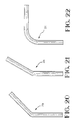
- Figures 20 to 23 show optical mixing rods 22a to 22d, respectively, having arcs of curvature of 30°, 45°, 90°, and 135°, respectively.
- Figure 24 shows a mixing rod 22e having a plurality of arcs of curvature of different value. Such arcs, or the combinations thereof shown in Figure 24 may be selected for mechanical reasons, for example. The uniformity achieved by the use of these mixing rods, has been found to be better than that achieved with the use of a rectilinear mixing rod.
- the mixing rod may be curved in a single plane, as shown, or it may be of spiral, for example, helical, form.
- Figure 25 shows mixing rods 22f of other than circular cross sectional shape, for use in a two fibre-to-two fibre coupling device.
Landscapes
- Physics & Mathematics (AREA)
- General Physics & Mathematics (AREA)
- Optics & Photonics (AREA)
- Optical Couplings Of Light Guides (AREA)
- Mechanical Coupling Of Light Guides (AREA)
Claims (16)
- Dispositif de couplage optique (16) pour transmettre une lumière émise par une première fibre optique (F7) à chacune d'une pluralité de deuxièmes fibres optiques (F1 à F7) formant un faisceau (F), le dispositif de couplage comprenant: des premier et deuxième connecteurs tubulaires (20) ayant chacun une embouchure d'entrée de fibres effilée vers l'avant (38) s'ouvrant dans une extrémité arrière (36) de ceux-ci, lesdits connecteurs (20) recevant lesdites premières et deuxièmes fibres, respectivement, avec une extrémité optique (7) de chaque fibre exposée au niveau d'une extrémité avant (33) du connecteur respectif (20) ; et une tige de mélange gainée, optique (22) interposée entre les extrémités avant des connecteurs, la tige de mélange (22) ayant des extrémités optiques (34, 56) interfacées optiquement avec les extrémités optiques (7) des premières et deuxièmes fibres optiques, respectivement, de manière à distribuer la lumière émise par la première fibre optique (F7) en vue d'éclairer les extrémités optiques des deuxièmes fibres optiques (F1 à F7), la tige de mélange (22) comprenant une partie centrale courbe (50) connectant des première et deuxième parties d'extrémité rectilignes (48, 54) de la tige de mélange, chacune se terminant dans une extrémité respective desdites extrémités optiques (34, 56) de la tige de mélange (22),
caractérisé en ce qu'au moins le deuxième connecteur tubulaire (20) est formé avec une série de rainures de guidage de fibres, s'étendant axialement, périphériques, internes (40) s'ouvrant dans l'extrémité avant (33) du connecteur (20), chaque rainure (40) recevant une fibre respective (F1 à F6) du faisceau (F), ces fibres respectives (F1 à F6) agissant ensemble pour retenir au moins une fibre centrale (F7) du faisceau (F) fermement en position en une relation parallèle avec des fibres respectives (F1 et F6) et chaque rainure (40) a une partie arrière d'entrée de fibres (44) s'effilant en largeur et en profondeur vers l'embouchure d'entrée de fibres du connecteur associé. - Dispositif selon la revendication 1, caractérisé en ce que la partie courbe (50) de la tige de mélange (22) est courbée selon un arc entre 30° et 180°.
- Dispositif selon la revendication 1 ou 2, caractérisé en ce que la partie courbe (50) de la tige de mélange (22) est courbée selon un arc d'approximativement 180°.
- Dispositif selon l'une quelconque des revendications précédentes, caractérisé en ce que le rayon de courbure de la partie courbe (50) de la tige de mélange (22) se situe entre 20mm et 50 mm.
- Dispositif selon l'une quelconque des revendications précédentes, caractérisé en ce que le rayon de courbure de ladite partie courbe (50) est approximativement de 45mm, la tige de mélange (22) ayant un diamètre global d'approximativement 3mm, où chacun des connecteurs (20) reçoit sept fibres optiques (F1 à F7).
- Dispositif selon l'une quelconque des revendications 1 à 4, caractérisé en ce que la tige de mélange (22) a un diamètre de coeur d'approximativement 4,52 mm, où chaque connecteur (20) reçoit treize fibres.
- Dispositif selon l'une quelconque des revendications 1 à 4, caractérisé en ce que la tige de mélange (22) a un diamètre de coeur d'approximativement 5,07 mm, où chaque connecteur (20) reçoit dix-neuf fibres.
- Dispositif selon l'une quelconque des revendications précédentes, caractérisé en ce que la transmission optique à travers la tige de mélange (22) se monte à au moins 99,98 % mesurée à une longueur d'onde de 660 nm.
- Dispositif selon l'une quelconque des revendications précédentes, caractérisé en ce que la tige de mélange (22) est une fibre de polycarbonate comportant une gaine.
- Dispositif selon l'une quelconque des revendications 1 à 8, caractérisé en ce que la tige de mélange (22) a un coeur en verre de silice pur et une gaine en verre de silice.
- Dispositif selon l'une quelconque des revendications 1 à 9, caractérisé en ce que la tige de mélange (22) a une gaine en une matière réfléchissant la lumière.
- Dispositif selon l'une quelconque des revendications précédentes, caractérisé en ce que la tige de mélange (22) a une ouverture numérique entre 0,40 et 0,70 adaptée aux fibres correspondantes.
- Dispositif selon l'une quelconque des revendications précédentes, caractérisé en ce que l'extrémité avant (33) de chaque connecteur (20) est reçue dans un logement tubulaire (18), qui reçoit aussi une extrémité optique respective (34, 56) de la tige de mélange (22), une matière d'adaptation d'indice de réfraction étant disposée dans l'interface (35) entre lesdites extrémités optiques dans le logement (18).
- Dispositif selon la revendication 13, caractérisé en ce que la matière d'adaptation d'indice de réfraction est une résine liquide ou adhésive.
- Dispositif selon l'une quelconque des revendications précédentes, caractérisé par un premier logement tubulaire (18) ayant une première partie d'alésage arrière axiale (26) recevant l'extrémité avant (33) du premier connecteur tubulaire (20), et un deuxième logement tubulaire (18) ayant une première partie d'alésage arrière axiale (26) recevant l'extrémité avant (33) du deuxième connecteur tubulaire (20), chaque logement (18) ayant une partie de deuxième alésage avant axiale (30) de section transversale inférieure à celle de ladite première partie (26), communiquant avec la première partie d'alésage (26) et recevant une extrémité optique respective (34, 56) de la tige de mélange (22).
- Dispositif selon la revendication 15, caractérisé en ce que chaque logement (18) est réalisé en une matière à faible indice de réfraction, la différence d'indice de réfraction entre le logement (18) et le coeur de la tige de mélange (22) entraínant une ouverture numérique de 0,50, ou au moins adaptée à la tige de mélange.
Applications Claiming Priority (4)
| Application Number | Priority Date | Filing Date | Title |
|---|---|---|---|
| GB9127367 | 1991-12-24 | ||
| GB919127369A GB9127369D0 (en) | 1991-12-24 | 1991-12-24 | Optical coupling device |
| GB919127367A GB9127367D0 (en) | 1991-12-24 | 1991-12-24 | Confining optical fibres |
| GB9127369 | 1991-12-24 |
Publications (3)
| Publication Number | Publication Date |
|---|---|
| EP0549332A2 EP0549332A2 (fr) | 1993-06-30 |
| EP0549332A3 EP0549332A3 (en) | 1993-08-18 |
| EP0549332B1 true EP0549332B1 (fr) | 1999-03-17 |
Family
ID=26300076
Family Applications (1)
| Application Number | Title | Priority Date | Filing Date |
|---|---|---|---|
| EP92311717A Expired - Lifetime EP0549332B1 (fr) | 1991-12-24 | 1992-12-22 | Dispositif de couplage optique |
Country Status (4)
| Country | Link |
|---|---|
| US (1) | US5408551A (fr) |
| EP (1) | EP0549332B1 (fr) |
| JP (1) | JPH05257029A (fr) |
| DE (1) | DE69228667T2 (fr) |
Families Citing this family (20)
| Publication number | Priority date | Publication date | Assignee | Title |
|---|---|---|---|---|
| US5841921A (en) * | 1997-01-31 | 1998-11-24 | Wallace; Troy B. | Optical coupling device |
| US5807242A (en) * | 1997-03-24 | 1998-09-15 | Synergetics, Inc. | Microsurgical laser probe with homogeneous laser light field |
| DE10021940A1 (de) * | 2000-05-05 | 2001-11-15 | Instr Systems Optische Messtec | Vorrichtung und Verfahren zum Übertragen von Licht über eine Dickkern-Faser |
| EP1319939A4 (fr) * | 2000-09-22 | 2005-11-23 | Organo Corp | Dispositif de mesure de concentration |
| WO2003023499A2 (fr) * | 2001-09-12 | 2003-03-20 | Tecan Trading Ag | Dispositif optique, systeme et utilisation |
| JP3922085B2 (ja) * | 2002-04-25 | 2007-05-30 | ヤマハ株式会社 | 光ファイバ束の保持構造 |
| DE10237202A1 (de) * | 2002-08-14 | 2004-02-26 | Carl Zeiss Jena Gmbh | Lichtmischstab |
| KR100510673B1 (ko) * | 2003-03-03 | 2005-08-31 | 엘지전자 주식회사 | 레이저 표시 장치 |
| DE10314289A1 (de) * | 2003-03-29 | 2004-10-07 | Schölly Fiberoptic GmbH | Bildleiter |
| US7561769B2 (en) | 2004-03-16 | 2009-07-14 | Sumitomo Electric Industries, Ltd. | Optical fiber for irradiation-light transfer and light irradiation device equipped with the same |
| DE102005010344B4 (de) * | 2005-03-07 | 2007-05-31 | CCS Technology, Inc., Wilmington | Vorrichtung zum Biegen eines Lichtwellenleiters sowie Anordnung zum Dämpfen von Licht in einem Lichtwellenleiter |
| US8444326B2 (en) * | 2008-05-30 | 2013-05-21 | 3M Innovative Properties Company | Flexible optical coupling |
| US8488937B2 (en) * | 2009-08-06 | 2013-07-16 | Tyco Electronics Canada, Ulc | Light distribution assembly |
| JP5771977B2 (ja) * | 2010-12-22 | 2015-09-02 | コニカミノルタ株式会社 | 光ファイバフェルール |
| EP2579075A1 (fr) | 2011-10-06 | 2013-04-10 | Ivoclar Vivadent AG | Conducteur de lumière de forme cylindrique |
| US10564357B2 (en) | 2013-07-30 | 2020-02-18 | The Boeing Company | Plastic optical fiber bus network using tapered mixing rods |
| US11300730B2 (en) * | 2013-07-30 | 2022-04-12 | The Boeing Company | Plastic and glass optical fiber bus network having plural line replaceable units transmitting to a mixing rod |
| US9322987B2 (en) * | 2013-08-27 | 2016-04-26 | International Business Machines Corporation | Multicore fiber coupler between multicore fibers and optical waveguides |
| US9778419B1 (en) | 2016-06-23 | 2017-10-03 | The Boeing Company | Fiber optical system with fiber end face area relationships |
| US10263706B2 (en) * | 2017-04-18 | 2019-04-16 | The Boeing Company | Single-fiber bidirectional controller area network bus |
Family Cites Families (11)
| Publication number | Priority date | Publication date | Assignee | Title |
|---|---|---|---|---|
| US3969016A (en) * | 1975-05-09 | 1976-07-13 | Bell Telephone Laboratories, Incorporated | Low dispersion optical fiber wave guiding structures with periodically deformed waveguide axis |
| FR2331802A1 (fr) * | 1975-11-14 | 1977-06-10 | Thomson Csf | Dispositif coupleur optique pour interconnexion de guides de lumiere dans un systeme de transmission optique, et systeme de transmission correspondant |
| US4125315A (en) * | 1976-07-28 | 1978-11-14 | Vivitar Corporation | Light mixing device |
| FR2366588A1 (fr) * | 1976-10-01 | 1978-04-28 | Thomson Csf | Coupleur multivoies pour liaison par fibres optiques |
| FR2372442A1 (fr) * | 1976-11-30 | 1978-06-23 | Thomson Csf | Dispositif coupleur pour interconnexion de guides d'ondes optiques et systeme de transmission optique comportant un tel dispositif |
| US4676594A (en) * | 1984-11-16 | 1987-06-30 | American Telephone And Telegraph Company | Optical fiber mode scrambler |
| EP0347233A3 (fr) * | 1988-06-16 | 1991-02-13 | Gec-Marconi Limited | Dispositif d'optique intégrée |
| US5058979A (en) * | 1989-06-22 | 1991-10-22 | Fujikura Ltd. | Optical fiber coupler and a fabrication method for the same |
| US4995692A (en) * | 1990-02-06 | 1991-02-26 | General Motors Corporation | Fiber optic star coupler |
| US5018814A (en) * | 1990-02-13 | 1991-05-28 | Physical Optics Corporation | Broadband single-mode optical coupler |
| US5054874A (en) * | 1990-12-17 | 1991-10-08 | Her Majesty The Queen In Right Of Canada, As Represented By The Minister Of Communications | Coupler fabrication techniques for dissimilar fibers |
-
1992
- 1992-12-22 EP EP92311717A patent/EP0549332B1/fr not_active Expired - Lifetime
- 1992-12-22 DE DE69228667T patent/DE69228667T2/de not_active Expired - Fee Related
- 1992-12-24 JP JP4357554A patent/JPH05257029A/ja active Pending
-
1993
- 1993-11-22 US US08/156,521 patent/US5408551A/en not_active Expired - Fee Related
Also Published As
| Publication number | Publication date |
|---|---|
| JPH05257029A (ja) | 1993-10-08 |
| DE69228667T2 (de) | 1999-09-30 |
| DE69228667D1 (de) | 1999-04-22 |
| EP0549332A3 (en) | 1993-08-18 |
| US5408551A (en) | 1995-04-18 |
| EP0549332A2 (fr) | 1993-06-30 |
Similar Documents
| Publication | Publication Date | Title |
|---|---|---|
| EP0549332B1 (fr) | Dispositif de couplage optique | |
| US3950075A (en) | Light source for optical waveguide bundle | |
| US3995935A (en) | Optical coupler | |
| US5757994A (en) | Three-part optical coupler | |
| US4836637A (en) | Expanded-beam fiber-optic connector | |
| US4705352A (en) | Fiber optic connector | |
| US4400054A (en) | Passive optical coupler | |
| EP0307487B1 (fr) | Collimateur pour des fibres optiques | |
| EP0080887A2 (fr) | Modules de communication à fibres optiques | |
| KR940002621A (ko) | 섬유 광 커플러 및 이의 제조방법 | |
| CA2056925A1 (fr) | Optocoupleur et amplificateur a fibres optiques | |
| US4530566A (en) | Optical fiber duplex coupler | |
| US5666448A (en) | Variable splitting optical coupler | |
| EP1979772B1 (fr) | Fibre optique chemisée pour une perte latérale réduite et procédé pour fabriquer celle-ci | |
| US4722582A (en) | Optical-fibre coupler | |
| CN112946821A (zh) | 基于套管法的模组选择光子灯笼制备方法 | |
| GB2094995A (en) | Optical distributors using optical fibres | |
| CN211698277U (zh) | 光纤准直器 | |
| US5071217A (en) | Precision focusing and locating collar for a fiber optic connector | |
| US4995692A (en) | Fiber optic star coupler | |
| US4718746A (en) | Optical fiber graded index connector | |
| US6350065B1 (en) | Optical fiber splicing mechanism, optical fiber structure, and optical fiber splicing method | |
| US6798949B2 (en) | Optical assembly with integrated lens protrusion | |
| NO148201B (no) | Tilslutningsinnretning for fiberoptiske kommunikasjonssystemer | |
| JPS62119508A (ja) | 複数光ファイバ集束用溝付フェル−ルを備えた光多分配型半導体レ−ザモジュ−ル |
Legal Events
| Date | Code | Title | Description |
|---|---|---|---|
| PUAI | Public reference made under article 153(3) epc to a published international application that has entered the european phase |
Free format text: ORIGINAL CODE: 0009012 |
|
| PUAL | Search report despatched |
Free format text: ORIGINAL CODE: 0009013 |
|
| AK | Designated contracting states |
Kind code of ref document: A2 Designated state(s): DE ES FR GB IT NL SE |
|
| AK | Designated contracting states |
Kind code of ref document: A3 Designated state(s): DE ES FR GB IT NL SE |
|
| 17P | Request for examination filed |
Effective date: 19940122 |
|
| 17Q | First examination report despatched |
Effective date: 19950808 |
|
| GRAG | Despatch of communication of intention to grant |
Free format text: ORIGINAL CODE: EPIDOS AGRA |
|
| GRAG | Despatch of communication of intention to grant |
Free format text: ORIGINAL CODE: EPIDOS AGRA |
|
| GRAH | Despatch of communication of intention to grant a patent |
Free format text: ORIGINAL CODE: EPIDOS IGRA |
|
| GRAH | Despatch of communication of intention to grant a patent |
Free format text: ORIGINAL CODE: EPIDOS IGRA |
|
| RBV | Designated contracting states (corrected) |
Designated state(s): DE FR GB |
|
| GRAA | (expected) grant |
Free format text: ORIGINAL CODE: 0009210 |
|
| AK | Designated contracting states |
Kind code of ref document: B1 Designated state(s): DE FR GB |
|
| REF | Corresponds to: |
Ref document number: 69228667 Country of ref document: DE Date of ref document: 19990422 |
|
| ET | Fr: translation filed | ||
| PLBE | No opposition filed within time limit |
Free format text: ORIGINAL CODE: 0009261 |
|
| STAA | Information on the status of an ep patent application or granted ep patent |
Free format text: STATUS: NO OPPOSITION FILED WITHIN TIME LIMIT |
|
| 26N | No opposition filed | ||
| REG | Reference to a national code |
Ref country code: GB Ref legal event code: IF02 |
|
| PGFP | Annual fee paid to national office [announced via postgrant information from national office to epo] |
Ref country code: GB Payment date: 20031105 Year of fee payment: 12 |
|
| PGFP | Annual fee paid to national office [announced via postgrant information from national office to epo] |
Ref country code: FR Payment date: 20031201 Year of fee payment: 12 |
|
| PGFP | Annual fee paid to national office [announced via postgrant information from national office to epo] |
Ref country code: DE Payment date: 20031230 Year of fee payment: 12 |
|
| PG25 | Lapsed in a contracting state [announced via postgrant information from national office to epo] |
Ref country code: GB Free format text: LAPSE BECAUSE OF NON-PAYMENT OF DUE FEES Effective date: 20041222 |
|
| PG25 | Lapsed in a contracting state [announced via postgrant information from national office to epo] |
Ref country code: DE Free format text: LAPSE BECAUSE OF NON-PAYMENT OF DUE FEES Effective date: 20050701 |
|
| GBPC | Gb: european patent ceased through non-payment of renewal fee |
Effective date: 20041222 |
|
| PG25 | Lapsed in a contracting state [announced via postgrant information from national office to epo] |
Ref country code: FR Free format text: LAPSE BECAUSE OF NON-PAYMENT OF DUE FEES Effective date: 20050831 |
|
| REG | Reference to a national code |
Ref country code: FR Ref legal event code: ST |