EP0549708B1 - Medizinische waschvorrichtung - Google Patents
Medizinische waschvorrichtung Download PDFInfo
- Publication number
- EP0549708B1 EP0549708B1 EP91918090A EP91918090A EP0549708B1 EP 0549708 B1 EP0549708 B1 EP 0549708B1 EP 91918090 A EP91918090 A EP 91918090A EP 91918090 A EP91918090 A EP 91918090A EP 0549708 B1 EP0549708 B1 EP 0549708B1
- Authority
- EP
- European Patent Office
- Prior art keywords
- aspiration
- plunger
- irrigation
- bore
- syringe
- Prior art date
- Legal status (The legal status is an assumption and is not a legal conclusion. Google has not performed a legal analysis and makes no representation as to the accuracy of the status listed.)
- Expired - Lifetime
Links
- 230000002262 irrigation Effects 0.000 claims abstract description 93
- 238000003973 irrigation Methods 0.000 claims abstract description 93
- 239000012530 fluid Substances 0.000 claims description 48
- 239000000463 material Substances 0.000 claims description 2
- 238000007789 sealing Methods 0.000 claims 1
- 239000002699 waste material Substances 0.000 description 10
- 239000012528 membrane Substances 0.000 description 8
- 210000000056 organ Anatomy 0.000 description 8
- 239000004033 plastic Substances 0.000 description 3
- 229920004142 LEXAN™ Polymers 0.000 description 2
- 239000004418 Lexan Substances 0.000 description 2
- 230000009286 beneficial effect Effects 0.000 description 2
- 239000004417 polycarbonate Substances 0.000 description 2
- 229920000515 polycarbonate Polymers 0.000 description 2
- 238000003466 welding Methods 0.000 description 2
- 239000000853 adhesive Substances 0.000 description 1
- 230000001070 adhesive effect Effects 0.000 description 1
- 230000000903 blocking effect Effects 0.000 description 1
- 230000000994 depressogenic effect Effects 0.000 description 1
- 238000004090 dissolution Methods 0.000 description 1
- 230000000694 effects Effects 0.000 description 1
- 239000007788 liquid Substances 0.000 description 1
- 210000003660 reticulum Anatomy 0.000 description 1
- 239000007787 solid Substances 0.000 description 1
Images

Classifications
-
- A—HUMAN NECESSITIES
- A61—MEDICAL OR VETERINARY SCIENCE; HYGIENE
- A61M—DEVICES FOR INTRODUCING MEDIA INTO, OR ONTO, THE BODY; DEVICES FOR TRANSDUCING BODY MEDIA OR FOR TAKING MEDIA FROM THE BODY; DEVICES FOR PRODUCING OR ENDING SLEEP OR STUPOR
- A61M5/00—Devices for bringing media into the body in a subcutaneous, intra-vascular or intramuscular way; Accessories therefor, e.g. filling or cleaning devices, arm-rests
- A61M5/178—Syringes
- A61M5/19—Syringes having more than one chamber, e.g. including a manifold coupling two parallelly aligned syringes through separate channels to a common discharge assembly
-
- A—HUMAN NECESSITIES
- A61—MEDICAL OR VETERINARY SCIENCE; HYGIENE
- A61M—DEVICES FOR INTRODUCING MEDIA INTO, OR ONTO, THE BODY; DEVICES FOR TRANSDUCING BODY MEDIA OR FOR TAKING MEDIA FROM THE BODY; DEVICES FOR PRODUCING OR ENDING SLEEP OR STUPOR
- A61M1/00—Suction or pumping devices for medical purposes; Devices for carrying-off, for treatment of, or for carrying-over, body-liquids; Drainage systems
- A61M1/71—Suction drainage systems
- A61M1/77—Suction-irrigation systems
- A61M1/772—Suction-irrigation systems operating alternately
-
- A—HUMAN NECESSITIES
- A61—MEDICAL OR VETERINARY SCIENCE; HYGIENE
- A61M—DEVICES FOR INTRODUCING MEDIA INTO, OR ONTO, THE BODY; DEVICES FOR TRANSDUCING BODY MEDIA OR FOR TAKING MEDIA FROM THE BODY; DEVICES FOR PRODUCING OR ENDING SLEEP OR STUPOR
- A61M5/00—Devices for bringing media into the body in a subcutaneous, intra-vascular or intramuscular way; Accessories therefor, e.g. filling or cleaning devices, arm-rests
- A61M5/178—Syringes
- A61M5/31—Details
- A61M5/315—Pistons; Piston-rods; Guiding, blocking or restricting the movement of the rod or piston; Appliances on the rod for facilitating dosing ; Dosing mechanisms
Definitions
- This invention relates broadly to the art of medical lavage devices and particularly to those which can be used for quickly exchanging fluids of body cavities.
- This invention can be used with medical lavage apparatus of the type disclosed in U.S. Patents 4,872,866 and 4,842,581 to Davis.
- GB-A-2 048 077 discloses a hypodermic syringe which includes a cylinder housing and a plunger in a bore of the cylinder housing, the syringe having an aperture which corresponds in shape to the cross-section of the plunger to restrict rotational movement of the plunger in the bore.
- the aperture is in the shape of a cruciform.
- Patents 4,872,866 and 4,842,581 to Davis describe medical lavage apparatus comprising parallel irrigation and aspiration cylinders communicating with a common exchange tube.
- the irrigation cylinder includes an inlet port and the aspiration cylinder includes an outlet port through which fluid from a supply container is pumped into and out of the body cavity as irrigation and aspiration plungers are moved in their respective cylinders.
- These patents disclose an anti-venturi septum and various valves which channel fluid flow from a supply container into the body cavity and out of the body cavity through the outlet port to a waste container.
- These patents also disclose loop handles having adjacent, relatively-straight, parallel, sides positioned close to each other to allow a user to grip and operate both the irrigation and aspiration plungers at the same time as well as individually.
- a feature of the medical lavage syringe device of U.S. Patents 4,872,866 and 4,842,581 to Davis is that when the aspiration plunger thereof is fully inserted in its aspiration cylinder its seal covers the outlet port so that the irrigation plunger can be operated to pump fluid from the supply container into the cavity to be evacuated without fear of this fluid passing directly to the outlet port.
- fluid pressure tends to move the aspiration plunger away from the fully seated position, thereby again uncovering the outlet port and allowing fluid to by-pass directly from the inlet port to the outlet port without going into the cavity to be irrigated. It is therefore an object of this invention, to provide a medical lavage syringe device of the type described in which an irrigation plunger thereof can be independently operated with assurance that fresh evacuation fluid is pumped into a cavity to be evacuated.
- the loop handles of the above described patents can only be gripped in a manner intended for operating both the irrigation and the aspiration plungers simultaneously when they are aligned with one another.
- the plungers tend to rotate easily in their respective cylinders so that when the plungers are operated individually, the handles tend to come out of alignment.
- a syringe including a cylinder housing and a plunger in a bore of said cylinder housing, said syringe having means to restrict rotational movement of said plunger in said bore, which syringe is characterised in that the plunger has a longitudinal rib and said syringe has a separate tab for extending from an outer surface of said cylinder housing through an opening in said cylinder housing into said bore to engage said plunger, which tab comprises two closely spaced legs which closely straddle said longitudinal rib to immediately engage opposite sides thereof, thereby preventing substantial rotation of said plunger while allowing longitudinal movement of said plunger.
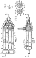
- a lavage apparatus 10 is shown in Figure 1 for use with a supply container 12, a supply tube 14, a waste container 16 and a waste tube 18.
- the lavage apparatus 10 comprises a rigid housing 20, a common exchange tube 22, an irrigation plunger 24, an aspiration plunger 26, and a system of seals and valves associated therewith.
- the rigid housing 20 is molded as one piece of a medical grade, translucent polycarbonate (LEXAN, a trademark of General Electric) plastic.
- the rigid housing 20 has an irrigation cylinder 28 defining an irrigation-cylinder bore 30, an aspiration-cylinder 32 defining an aspiration cylinder bore 34, first and second supporting flanges 36 and 38 holding together first ends of the irrigation and aspiration cylinders 28 and 32, a third flange 40 holding together second ends of the irrigation and aspiration cylinders 28 and 32, an inlet port 42 located near a second end of the irrigation cylinder 28, an outlet port 44 located near a second end of the aspiration cylinder 32, an irrigation check-valve cylinder 46 located at the end of the irrigation cylinder 28 and an aspiration check-valve cylinder 48 located at the second end of the aspiration cylinder 32, and an anti-venturi septum 50 joining the second ends of the irrigation and aspiration check-valve cylinders 46 and 48.
- LEXAN translucent polycarbonate
- the first, second, and third flanges 36, 38, and 40 hold the irrigation cylinder 28 and the aspiration cylinder 32 in a side-by-side, parallel, relationship.
- the bores 30 and 34 of the respective irrigation and aspiration cylinders 28 and 32 are the same size, each providing approximately 125 cc's in actual stroke volume when the plungers are withdrawn to stops thereof.
- the inlet and outlet ports 42 and 44 are close to the second ends 52 of the irrigation and aspiration cylinders 28 and 32 in the form of small, equal sized, valve cylinders extending perpendicular to axes of the irrigation and aspiration cylinders 28 and 32. This increases the turbulence of fluid flow allowing for increased mixing and dissolution of aspirated contents thereby reducing valve clogging.
- the equal sized irrigation and aspiration check-valve cylinders 46 and 48 are connected to their respective irrigation and aspiration cylinders 28 and 32 by tapered bonnets 54 and 56, respectively so as to be close to, and parallel with one another.
- the circumference of the check-valve cylinders 46 and 48 is about half that of the irrigation and aspiration cylinders 28 and 32 and their axes are offset from those of the irrigation and aspiration cylinders 28 and 32 so that the irrigation and aspiration check-valve cylinders 46 and 48 are close to one another with their bores aligned with the irrigation and aspiration cylinder bores 30 and 34.
- the septum 50 has an irrigation baffle 58 and an aspiration baffle 60, each of which is semi-circular in cross-sectional shape. These baffles intersect at an outer tip 62 which forms a U-shaped line.
- the septum baffles 58 and 60 are only positioned on the inside sides of the check-valve cylinders 46 and 48 so as to guide fluid from and to the check-valve cylinders 46 and 48.
- a fourth flange 64 interconnects the outer ends of the check-valve cylinders 46 and 48 and forms an oval with these outer ends.
- the plungers 24 and 26 are molded to be identical, each having shafts comprised of crossed longitudinal ribs 69a-d (for the irrigation plunger) and 68a-d (for the aspiration plunger) supported circumferentially by circumferential ribs 70. Also molded integral therewith are finger-engaging portions 72 and seal-mounting ribs 74. Seal-mounting ribs 74 are separated from stop or last circumferential ribs 70' by a space 76 into which internally directed ribs (not shown) of seals 80 are inserted for holding the seals thereon. Each seal 80 has a cone-shaped end 82 with small ridges 84 thereon. There are three cylinder-bore contacting rings 83a, b, and c on the outer surface thereof.
- the finger-engaging portions 72 of the plungers 24 and 26 are respectively turned so that they provide mirror images, one of the other.
- the finger-engaging portions 72 are not geometrical, being flat at first sides 86 thereof and rounded at second sides 88 thereof. The reason for this is so that the first sides 86 can be as close together, between two adjacent fingers, as possible where it is desirable to operate the syringes simultaneously.
- these finger-engaging portions are designed to allow easy use of one of the plungers or both as is desired. This allows one to "prime the pump", so to speak, with the irrigation half of the system upon beginning use of the lavage apparatus.
- the common exchange tube 22 is oblong, or oval, in cross section to thereby form an oblong chamber 91 in which fluid flows to and from the irrigation and aspiration cylinders 28 and 32.
- the common exchange tube 22 includes an apron portion 90, a manifold portion 92, a common nozzle portion 94, and an attachment ridge 96.
- the attachment ridge 96 is of a size to sealingly fit about the side-by-side irrigation and aspiration check-valve cylinders 46 and 48 and the fourth flange 64 which joins them. In use, these members are held together by sonic welding or by an adhesive.
- the apron portion 90 makes the entire apparatus more streamlined in appearance and for handling, however, it is not necessary for operation of the lavage apparatus.
- the manifold portion 92 encloses and seals with outer ends 98 and 100 of the irrigation and aspiration check-valve cylinders 46 and 48 as well as the septum 50, as can be seen in Figure 2, so that all material flowing to and from the outer ends 98 and 100 are guided by the septum 50 and the manifold portion 92. Similarly, all fluids flowing to and from the manifold portion 92 flow through the common nozzle 94. It should be noted that the septum 50 is so arranged and designed that fluid streams flowing from the irrigation check-valve cylinder 46 will be directed into the nozzle 94 and fluid flowing from the nozzle 94 will be directed to the aspiration check-valve cylinder 48 without restriction and without causing undue turbulence.
- the U-shaped outer tip line 62 particularly aids in avoiding undue cross mixing by not causing a venturi restriction to create a negative pressure in the manifold portion 92 which improperly opens a check-valve. Sidewalls of the septum 50 press against interior surfaces of the manifold at 101 to create a seal therebetween.
- an irrigation check-valve 102 has a cylinder outer wall with a cross-wall carrying a resilient membrane 104 thereon which flexes open when pressure is exerted from the irrigation-cylinder bore 30 toward the nozzle 94 but close when pressure is exerted in the opposite direction.
- An aspiration check-valve 106 in the aspiration check-valve cylinder 48 operates in a similar but opposite manner.
- An inlet check-valve 108, with an attached membrane 110 allows fluid to flow into the irrigation cylinder 28, but does not allow flow from the irrigation cylinder 28.
- an outlet check-valve 112 allows fluid flow from the aspiration cylinder 32, however, it does not allow flow therein.
- Funnel-like inlet and outlet adapters 116 and 118 are respectively attached to the inlet port 42 and the outlet port 44.
- inlet and outlet ports 42 and 44 are each restricted by a shelf 119 ( Figure 4) which makes an actual port opening 120 have an elongated (semicircular) shape and have the same cross-sectional area as the bore of the nozzle 94.
- the approximate matching of these sizes balances pressures within the system so as to avoid improper opening of the check-valves during operation and thereby avoid cross mixing of contaminated and pure fluids.
- the shelves 119 have the additional purpose of creating elongated port openings 120 which allow the openings 120 to be fully sealed by the relatively-close-together contacting rings 83a, b, and c when the respective plungers 24 and 26 are fully depressed, as shown in Figure 4.
- the shelf 119 at the aspiration outlet port 44 tends to break up solids which might otherwise jam the membrane 114.
- the shelves 119 allow rather large membrane type check-valves to be used with necessarily smaller valve openings 120. These larger check-valves are not as vulnerable to jamming as smaller ones.
- All of the various rigid components of this invention can be constructed of a rigid hard resinous plastic such as polycarbonate (LEXAN).
- a rigid hard resinous plastic such as polycarbonate (LEXAN).
- the rigid housing 20, the two plungers 24 and 26, the common exchange tube 22, and the various check-valve cylinders 102, 106, 108, and 112 and the inlet and outlet adapters 116 and 118 are molded of hard resinous plastic.
- all of the check-valves are the same size so as not to require more than one mold for these elements.
- the plunger seal 80 and the various check-valve membranes are molded, or purchased off-the-shelf.
- the plunger seals 80 are attached to plungers 24 and 26 and the various check-valve membranes are attached to knobs on the check-valve cylinders 102, 106, 108, and 112.
- the check-valve cylinders are then attached by press fitting or sonic welding in their respective positions to the rigid housing 20 as is depicted in the exploded view of Figure 1. Thereafter, the attachment ridge 96 of the common exchange tube 22 is sealingly adhered to the irrigation and aspiration check-valve cylinders 46 and 48 and the flange 64 which adjoins these two ridges.
- the various valves cannot be easily serviced, but that is not necessary since the lavage apparatus is designed to be a single use, disposable product.
- the lavage apparatus 10 To utilize the lavage apparatus 10 one places a lavage liquid in the supply container 12 which is joined via a supply tube 14 and the inlet adaptor 116 to the inlet port 42.
- the waste container 16 is similarly attached via tube 18 and outlet adaptor 118 to the outlet port 44.
- the lavage solution is to be instilled into a body cavity, left for a short length of time and then sucked out.
- a tube (not shown) is attached to the nozzle 94 of the common exchange tube 22 which is inserted through an opening in the human body into an organ to be lavaged. Where fluid from more than one irrigation cylinder 28 is to be inserted into the organ before any is aspirated, the aspiration plunger 26 is inserted fully into the aspiration cylinder 32 as is depicted in Figures 2 and 4.
- the aspiration plunger seal 80 completely seals the opening 120 of the outlet port 44.
- the irrigation plunger 24 is pulled outwardly to cause a vacuum in the irrigation cylinder 28.
- This vacuum respectfully opens the membrane 110 of the inlet check-valve 108 and closes the membrane 104 of the irrigation check-valve 102.
- fluid is sucked from the supply container 12 into the irrigation cylinder 28.
- the irrigation plunger 24 is driven into the irrigation cylinder 28 which closes the inlet check-valve 108, opens the irrigation check valve 102, and drives fluid out of the irrigation cylinder 28 into the manifold portion 92 of the common exchange tube 22 and out the nozzle 94 of the common exchange tube 22.
- the irrigation baffle 58 of the septum 50 guides this fluid to ensure that it enters the nozzle 94 rather than being driven through the aspiration check-valve cylinder 48 to open the aspiration check-valve 106 and thereby drive the plunger 26 from its blocking position.
- the irrigator plunger 24 is moved in and out until the body cavity has the right amount of fluid in it.
- the irrigation plunger 24 is driven fully into the irrigation cylinder 28 so that seal 80 covers the openings 120 of the inlet port 42 thereby not allowing flow of fluid through this port.
- the aspiration plunger is pulled out and pushed in, thereby sucking contaminated fluid from the body organ through the nozzle 94, and the aspiration check-valve cylinder 48, into the aspiration cylinder 32, driving the contaminated waste fluid out of the outlet port 44 into the waste container.
- the pressures applied at each of these by the equal size plungers 24 and 26 are approximately equal, there being only a small drop across each of the various valves to cause them to act as check-valves in the appropriate directions.
- the shape of the U-shaped outer tip line 62 of the anti-venturi septum 50 does not cause undue venturi or eddy effects which create undue changes in pressure at the nozzle 94 to improperly open the irrigation and aspiration check valves 102 and 106 to cause a mixing.
- each of these tabs 122a-d comprises a relatively thin base plate 124 having spaced spring legs 126 extending from a bottom surface thereof.
- the base plate 124 is slightly rounded to the circular outer surface contours of the irrigation and aspiration cylinders 28 and 32.
- the irrigation and aspiration cylinders 28 and 32 each have tab openings 128a, b, c, and d therein for receiving the spring legs 126 of the tabs.
- the spring legs 126 include ramp surfaces 130 ( Figure 5) and shoulders 132 such that when the spring legs 126 of a tab are inserted through a tab opening 128, the ramp surfaces engage end edges of the tab opening 128 forcing the spring legs 126 inwardly until the shoulders 132 are inside a cylinder bore. When this happens, the spring legs 126 can spring outwardly so that the shoulders 132 engage housing walls thereby preventing the tabs 122 from being removed from the tab openings 128.
- the tabs 122a-d are mounted in their respective tab openings 128a-d, their legs project into the appropriate bore 30 or 34, as can be seen in Figures 4 and 5.
- Another feature of the tab legs 126 is that when they are viewed from their bottom ends, as is depicted in Figure 3, they have angled camming surfaces 133 whose purpose is described below.
- the irrigation and aspiration plungers 24 and 26 are also constructed somewhat differently in this improvement.
- intermediate circumferential ribs 134a, b, c, and d for these plungers are notched at 136 adjacent a top longitudinal rib 68a and 69a.
- the longitudinal ribs 68a-d of the aspiration plunger differ from the longitudinal ribs 69a-d of the irrigation plunger 24 in that they include longitudinal notches 140 on outer edges thereof. Positions of the longitudinal notches 140 corresponding to axial, or longitudinal, positions of tab openings 128a and b in the aspiration cylinder 32.
- the apparatus is assembled by inserting the seals 80 and the stop, or last, circumferential ribs 70' of the plungers 24 and 26 into the open ends of the irrigation and aspiration cylinders 28 and 32 and shoving them past all of the tab openings 128a-d.
- the spring legs 126 of the guide/lock/stop tabs 122a-d are then inserted into their respective tab openings 128a-d until they are locked in place by the shoulders 132 on the spring legs 126.
- the irrigation and aspiration plungers 24 and 22 are held in rotative orientation as depicted in Figure 1 with the loops of the finger-engaging portions 72 aligned with one another, their straight sides 86 adjacent one another.
- the longitudinal ribs 68a and 69a are directed upwardly toward the middle of the tab openings 128 so that when the spring legs 126 are inserted into the tab openings 128a-d their legs straddle the respective longitudinal ribs 68a and 69a.
- the longitudinal rib 68a of the aspiration plunger 26 is positioned between the spring legs 126 of the guide/lock/stop tab 122a.
- the aspiration plunger 26 cannot normally be rotated because its longitudinal rib 168a engages the legs 126. However, if the aspiration plunger is fully inserted into the aspiration cylinder 32, the legs 126 then are aligned with the longitudinal notches 140 in the longitudinal ribs which allows clearance for the aspiration plunger 26 to be rotated. When the aspiration plunger 26 is rotated, one of the camming surfaces 135 of the spring legs 126 contacts one of the latching cam surfaces 142 of the intermediate circumferential rib 134a to thereby lock the aspiration plunger 26 in position.
- the irrigation plunger 24 can then be pulled in and out without fear of the aspiration plunger 26 moving from this fully inserted position in which its seal 80 covers the opening 120 of the outlet port 44.
- irrigating fluid cannot be transferred directly from the irrigation cylinder 28 through the outlet port 44, but rather, when the irrigation plunger 24 is worked, evacuation fluid is driven through the common exchange tube 22 into a cavity to be evacuated.
- the guide/lock/stop tabs 122a and c also serve as stops inasmuch as their spring legs 126 contact end or stop circumferential ribs 70' of the irrigation and aspiration plungers 24 and 26 to prevent these plungers from being removed form their respective cylinders.
- the intermediate circumferential ribs 134a-d have circumferential notches 136 therein for allowing these intermediate ribs to pass longitudinally past the various tabs.
- the improvements described herein maintain the rotational orientations of the irrigation and aspiration plungers 24 and 26 unless the aspiration plunger 26 is rotated to be locked in a fully inserted position in which a seal 80 covers the outlet port 44. It should be noted that the irrigation plunger 24 need not be locked inasmuch as when the aspiration plunger 26 is independently operated, the irrigation plunger 24 is sucked to a fully inserted position in which its seal 80 covers the inlet port 42.
Landscapes
- Health & Medical Sciences (AREA)
- Heart & Thoracic Surgery (AREA)
- Hematology (AREA)
- Anesthesiology (AREA)
- Biomedical Technology (AREA)
- Engineering & Computer Science (AREA)
- Vascular Medicine (AREA)
- Life Sciences & Earth Sciences (AREA)
- Animal Behavior & Ethology (AREA)
- General Health & Medical Sciences (AREA)
- Public Health (AREA)
- Veterinary Medicine (AREA)
- Pulmonology (AREA)
- Infusion, Injection, And Reservoir Apparatuses (AREA)
- External Artificial Organs (AREA)
Claims (14)
- Eine Spritze (10), die ein Zylindergehäuse (28, 32) und einen Kolben (24, 26) in einer Bohrung (30, 34) besagten Zylindergehäuses (28, 32) einschließt, wobei der Kolben eine Längsrippe (68a, 69a) aufweist, wobei die Spritze dadurch gekennzeichnet ist, daß die Spritze (10) Mittel aufweist, um die Drehbewegung besagten Kolbens (24, 26) in besagter Bohrung (30, 34) einzuschränken, welche ein separates Steckteil (122) zur Erstreckung von einer Außenseite besagten Zylindergehäuses (28, 32) durch eine Öffnung (128) in besagtem Zylindergehäuse (28, 32) hindurch in besagte Bohrung (30, 34) hinein umfassen, um mit besagtem Kolben (24, 26) in Eingriff zu kommen, wobei das Steckteil (122) zwei in engem Abstand voneinander angeordnete Schenkel (126) umfaßt, die rittlings eng auf besagter Längsrippe (68a, 69a) sitzen, um unmittelbar mit gegenüberliegenden Seiten derselben in Eingriff zu kommen, wodurch wesentliche Drehung besagten Kolbens (24, 26) verhindert wird, während eine Längsbewegung besagten Kolbens (24, 26) ermöglicht wird.
- Eine Spritze (10) nach Anspruch 1, wobei besagte Längsrippe (68a, 69a) eine Aussparung (140) darin aufweist, die eine Drehung besagten Kolbens (24, 26) ermöglicht, wenn die Aussparung (140) mit besagten mit Abstand voneinander angeordneten Schenkein (126) fluchtet.
- Eine Spritze nach einem vorangehenden Anspruch, wobei die Schenkel (126) mit einer Anschlagfläche (70') auf besagtem Kolben (24, 26) in Eingriff kommen, um zu verhindern, daß besagter Kolben (24, 26) aus besagter Bohrung (30, 34) herausgezogen wird.
- Eine Spritze nach einem vorangehenden Anspruch, wobei besagter Kolben (24, 26) Verriegelungsmittel (136) umfaßt zum Eingriff mit besagten Schenkeln (126) besagten Steckteils (122), das sich in die Bohrung (30, 34) hineinerstreckt, wenn besagter Kolben (24, 26) gedreht wird, um dadurch zu verhindern, daß besagter Kolben (24, 26) sich in besagter Bohrung (30, 34) in Längsrichtung bewegt.
- Eine Spritze nach Anspruch 1, wobei besagtes Gehäuse (28, 32) einen länglichen Spülzylinder (28) mit einer Spülbohrung (30) und einen länglichen Ansaugzylinder (32) mit einer Ansaugbohrung (34) umfaßt, wobei besagte Spül- und Ansaugzylinderbohrungen (30, 34) an ersten Enden derselben jeweils offen und unverbunden sind, wobei besagtes Gehäuse (20) weiter jeweils eine Einlaßöffnung (42) und eine Auslaßöffnung (44) in besagten entsprechenden Spül- und Ansaugzylindern (28, 32) zwischen besagten ersten und zweiten Enden derselben definiert, wobei besagtes Gehäuse (20) weiter ein gemeinsames Austauschrohr (22) an zweiten Enden besagter Spül- und Ansaugzylinderbohrungen (30, 34) einschließt, das in einer gemeinsamen Düse (94) endet; besagter Kolben (24, 26) einen Spülkolben (24) und einen Ansaugkolben (26) umfaßt mit ersten Enden (bei 74) zum entsprechenden Hineinpassen in besagte erste offene Enden besagter Spül- und Ansaugzylinder (28, 32) und mit Gleitdichtungen (80) an besagten ersten Enden derselben zur Herstellung abdichtenden, gleitenden Kontakts mit Innenzylinderflächen besagter entsprechenden Bohrungen (30, 34) und einschließlich Handgriffabschnitten (72) an zweiten Enden außerhalb der Zylinder (28, 32) zum Angriff einer Hand und dadurch in ihre entsprechenden Bohrungen (30, 34) hinein und daraus heraus von besagter Hand bewegt werdend; besagte Spritze (10) weiterhin ein System von Rückschlagventilen umfaßt, das ein Einlaßrückschlagventil (108) umfaßt, das an besagter Einlaßöffnung (42) angeordnet ist, um den Strom von frischem Spülfluid von einer Quelle (12) in besagte Einlaßöffnung (42) hinein zu ermöglichen, aber den Strom von Fluid aus besagter Einlaßöffnung (42) heraus zu verhindern, ein Auslaßrückschlagventil (112), das an besagter Auslaßöffnung (44) angeordnet ist, um den Strom von Ansaugfluid aus besagter Auslaßöffnung (44) heraus zu ermöglichen, aber den Strom von Fluid in besagte Auslaßöffnung (44) hinein zu verhindern, ein Spülrückschlagventil (102), das an besagter Spülbohrung (30) zwischen besagter Einlaßöffnung (42) und besagtem gemeinsamen Austauschrohr (22) angeordnet ist, um einen Strom aus der Spülbohrung (30) in besagtes gemeinsames Austauschrohr (22) hinein zu ermöglichen, aber den Strom von Fluid aus besagtem gemeinsamen Austauschrohr (22) in besagte Spülbohrung (30) hinein zu verhindern, und ein Ansaugrückschlagventil (106), das an besagter Ansaugbohrung (34) zwischen besagter Auslaßöffnung (44) und besagtem gemeinsamen Austauschrohr (22) angeordnet ist, um den Strom von Spülfluid aus besagtem gemeinsamen Austauschrohr (22) in besagte Ansaugbohrung (34) zu ermöglichen, aber den Strom in der entgegengesetzten Richtung zu verhindern; und wobei eine Bewegung besagten Spülkolbens (24) in besagte Spülbohrung (30) hinein und daraus heraus bewirkt, daß Fluid aus besagter Einlaßöffnung (42) zu besagtem gemeinsamen Austauschrohr (22) strömt, während eine Bewegung besagten Ansaugkolbens (26) in besagte Ansaugbohrung (34) hinein und daraus heraus bewirkt, daß Fluid aus besagtem Austauschrohr (22) zu besagter Auslaßöffnung (44) strömt.
- Eine Spritze nach Anspruch 5, wobei besagte Auslaßöffnung (44) durch eine Dichtung (80) darin blockiert ist, Material aus besagtem Austauschrohr (22) aufzunehmen, wenn besagter Ansaugkolben (26) sich in besagter eingeschobenen Stellung befindet.
- Eine Spritze nach Anspruch 6, wobei besagte Auslaßöffnung (44) in einer Seitenwand besagten Ansaugzylinders (32) angeordnet ist, um von einer verlängerten Achse desselben zur Seite weg gerichtet zu sein, und wobei besagter Ansaugkolben (26) angemessen lang ist und besagte Auslaßöffnung (44) angemessen angeordnet ist, so daß, wenn besagter Ansaugkolben (26) vollständig in besagten Ansaugzylinder (32) eingeschoben ist, besagte Dichtung (80), die eine Gleitdichtung (80) ist, sich über besagte Auslaßöffnung (44) hinaus erstreckt, um zwischen besagtem Austauschrohr (22) und besagter Auslaßöffnung (44) angeordnet zu sein, wenn besagter Ansaugkolben (26) sich in besagter eingeschobenen Stellung befindet.
- Eine Spritze nach Anspruch 7, wobei besagte Gleitdichtung (80) besagten Ansaugkolbens (26) eine derartige Größe aufweist, daß diejenigen Teile desselben, die normalerweise Gleitkontakt mit besagter Innenzylinderfläche besagter Ansaugbohrung (34) herstellen, groß genug sind, um besagte Auslaßöffnung (44 bei 120) abzudecken, und wobei besagte Auslaßöffnung (44) so angeordnet ist, daß, wenn besagter Ansaugkolben (26) in besagter eingeschobenen Stellung in besagtem Ansaugzylinder (32) verriegelt ist, besagte Gleitdichtung (80) besagte Auslaßöffnung (44) vollständig abdeckt, um den Strom von Fluid dort hindurch zu verhindern.
- Eine Spritze nach einem der Ansprüche 5 bis 8, wobei besagter Ansaugkolben (26) Umfangsrippen umfaßt, von denen eine besagte Verriegelungsmittel (136) bildet.
- Eine Spritze nach Anspruch 9, wobei besagte Umfangsrippe (136), die besagtes Verriegelungsmittel (136) bildet, eine abgeschrägte Nockenfläche (142) zum Eingriff mit besagten Schenkeln (126) besagten Steckteils (122a), das sich in besagte Ansaugbohrung (34) hineinerstreckt, aufweist.
- Eine Spritze nach Anspruch 10, wobei besagte Schenkel (126) besagten Steckteils (122a), das sich in besagte Ansaugbohrung (134) hineinerstreckt, eine abgeschrägte Nockenfläche (130) zum Kontakt mit besagter Umfangsrippe (136), die besagtes Verriegelungsmittel (136) bildet, aufweisen.
- Eine Spritze nach Anspruch 11, wobei besagte Schenkel (126) besagten Steckteils (122a), das sich in besagte Ansaugbohrung (34) hineinerstreckt, in Kontakt kommen mit besagter Umfangsrippe (136) besagten Kolbens (26), wenn besagter Kolben (26) gedreht wird.
- Eine Spritze nach Anspruch 8, wobei die Schenkel eine Drehung besagten Ansaugkolbens (26) verhindern, sofern besagter Kolben sich nicht in besagter eingeschobenen Stellung befindet.
- Eine Spritze nach einem der Ansprüche 5 bis 13, wobei besagte Handgriffabschnitte (72) besagter Spül- und Ansaugkolben (24, 26) Schlaufenkonfigurationen besitzen, wobei besagte Schlaufen aneinandergrenzende, relativ gerade, parallele Seiten (86) aufweisen, die nahe zueinander angeordnet sind, um es einem Benutzer zu ermöglichen, beide Handgriffabschnitte (72) mit seinen Fingern zu greifen, die eng zusammenliegen, wenn besagte Kolben (24, 26) von besagten Schenkein (126) geführt werden.
Applications Claiming Priority (3)
| Application Number | Priority Date | Filing Date | Title |
|---|---|---|---|
| US584141 | 1990-09-18 | ||
| US07/584,141 US5049135A (en) | 1990-09-18 | 1990-09-18 | Medical lavage apparatus |
| PCT/US1991/006592 WO1992004925A1 (en) | 1990-09-18 | 1991-09-17 | Medical lavage apparatus |
Publications (3)
| Publication Number | Publication Date |
|---|---|
| EP0549708A1 EP0549708A1 (de) | 1993-07-07 |
| EP0549708A4 EP0549708A4 (en) | 1994-05-11 |
| EP0549708B1 true EP0549708B1 (de) | 1997-10-29 |
Family
ID=24336084
Family Applications (1)
| Application Number | Title | Priority Date | Filing Date |
|---|---|---|---|
| EP91918090A Expired - Lifetime EP0549708B1 (de) | 1990-09-18 | 1991-09-17 | Medizinische waschvorrichtung |
Country Status (7)
| Country | Link |
|---|---|
| US (1) | US5049135A (de) |
| EP (1) | EP0549708B1 (de) |
| JP (1) | JP2977612B2 (de) |
| AT (1) | ATE159659T1 (de) |
| CA (1) | CA2088069C (de) |
| DE (1) | DE69128091T2 (de) |
| WO (1) | WO1992004925A1 (de) |
Families Citing this family (44)
| Publication number | Priority date | Publication date | Assignee | Title |
|---|---|---|---|---|
| US5116315A (en) * | 1989-10-03 | 1992-05-26 | Hemaedics, Inc. | Biological syringe system |
| US5401246A (en) * | 1991-06-13 | 1995-03-28 | U.S. Medical Instruments, Inc. | Retractable syringe with a closed barrel |
| US5254086A (en) * | 1992-07-31 | 1993-10-19 | Ballard Medical Products | Medical lavage apparatus and methods |
| US5290259A (en) * | 1993-02-18 | 1994-03-01 | Ultradent Products, Inc. | Double syringe delivery system |
| US5407424A (en) * | 1993-02-24 | 1995-04-18 | Scimed Life Systems, Inc. | Angioplasty perfusion pump |
| US5749968A (en) * | 1993-03-01 | 1998-05-12 | Focal, Inc. | Device for priming for improved adherence of gels to substrates |
| FR2706774A1 (en) * | 1993-06-23 | 1994-12-30 | Achard Michel | Medical apparatus intended in particular for spraying and/or suction of a fluid substance |
| FR2706775A1 (en) * | 1993-06-23 | 1994-12-30 | Achard Michel | Tip intended for an apparatus for dispensing and/or sampling a fluid substance, in particular in the medical field, and apparatus allowing its implementation |
| CA2197671A1 (en) * | 1994-06-15 | 1995-12-21 | Hubert Menendez | Locking device for syringe or like instrument |
| US5656035A (en) * | 1995-04-25 | 1997-08-12 | Avoy; Donald R. | Refillable fibrinogen dispensing kit |
| CA2306513C (en) | 1997-04-14 | 2008-06-17 | Biosurgical Corporation | Medical suctioning apparatus and methods of use |
| US6331172B1 (en) | 1997-04-14 | 2001-12-18 | Baxter International Inc. | Applicator for dispensing measured quantities with use of controlled suction |
| US6090092A (en) | 1997-12-04 | 2000-07-18 | Baxter International Inc. | Sliding reconstitution device with seal |
| WO1999032173A1 (en) * | 1997-12-19 | 1999-07-01 | United States Surgical Corporation | Two component dispenser system |
| US6884230B1 (en) | 1998-03-09 | 2005-04-26 | Baxter International Inc. | Dispensing head for a tissue sealant applicator and process of use |
| US6047861A (en) * | 1998-04-15 | 2000-04-11 | Vir Engineering, Inc. | Two component fluid dispenser |
| US20050137566A1 (en) | 2003-12-23 | 2005-06-23 | Fowles Thomas A. | Sliding reconstitution device for a diluent container |
| AR021220A1 (es) | 1998-09-15 | 2002-07-03 | Baxter Int | DISPOSITIVO DE CONEXIoN PARA ESTABLECER UNA COMUNICACIoN FLUíDA ENTRE UN PRIMER RECIPIENTE Y UN SEGUNDO RECIPIENTE. |
| US6022339A (en) | 1998-09-15 | 2000-02-08 | Baxter International Inc. | Sliding reconstitution device for a diluent container |
| US7074216B2 (en) | 1998-09-15 | 2006-07-11 | Baxter International Inc. | Sliding reconstitution device for a diluent container |
| US7358505B2 (en) | 1998-09-15 | 2008-04-15 | Baxter International Inc. | Apparatus for fabricating a reconstitution assembly |
| US6921380B1 (en) | 1998-10-01 | 2005-07-26 | Baxter International Inc. | Component mixing catheter |
| US7175336B2 (en) * | 2001-01-26 | 2007-02-13 | Depuy Acromed, Inc. | Graft delivery system |
| US7077339B2 (en) * | 2003-02-03 | 2006-07-18 | Biomet, Inc. | Spray applicator |
| US7172579B2 (en) * | 2003-09-09 | 2007-02-06 | Civco Medical Instruments Co., Inc. | System and method for irrigation and tissue evacuation and collection |
| US7641851B2 (en) | 2003-12-23 | 2010-01-05 | Baxter International Inc. | Method and apparatus for validation of sterilization process |
| US7766900B2 (en) | 2005-02-21 | 2010-08-03 | Biomet Manufacturing Corp. | Method and apparatus for application of a fluid |
| US7635343B2 (en) * | 2005-04-21 | 2009-12-22 | Arteriocyte Medical Systems, Inc. | Fluid dispenser |
| GB2437783B (en) * | 2006-04-26 | 2011-11-02 | Summit Medical Ltd | A medical treatment material delivery apparatus |
| US20090062741A1 (en) * | 2006-11-14 | 2009-03-05 | Emery Smith | Dual lumen syringe |
| US9504816B2 (en) * | 2008-03-17 | 2016-11-29 | Syringetech Llc | Multi-mode syringe |
| US8518272B2 (en) | 2008-04-04 | 2013-08-27 | Biomet Biologics, Llc | Sterile blood separating system |
| US8182769B2 (en) | 2008-04-04 | 2012-05-22 | Biomet Biologics, Llc | Clean transportation system |
| US8033483B2 (en) | 2008-04-25 | 2011-10-11 | Confluent Surgical Inc. | Silicone spray tip |
| US8408480B2 (en) * | 2008-04-25 | 2013-04-02 | Confluent Surgical, Inc. | Self-cleaning spray tip |
| US8403834B2 (en) * | 2008-08-22 | 2013-03-26 | Fujifilm Corporation | Automatic return syringe with ventilation paths for air and suction ports |
| US8210453B2 (en) | 2008-09-12 | 2012-07-03 | Confluent Surgical, Inc. | Spray applicator |
| US10309430B2 (en) | 2012-08-10 | 2019-06-04 | Confluent Surgical, Inc. | Pneumatic actuation assembly |
| KR102023143B1 (ko) * | 2012-11-08 | 2019-09-19 | 술저 믹스팩 아게 | 2개 이상의 유동성 성분을 위한 카트리지 |
| WO2014152712A1 (en) | 2013-03-15 | 2014-09-25 | Merit Medical Systems, Inc. | Lockable syringe assemblies and related devices and methods |
| EP3125774B1 (de) | 2014-04-04 | 2020-05-27 | HyperBranch Medical Technology, Inc. | Sprühapplikator mit verlängerter spitze für chirurgisches zwei-komponenten-dichtmittel und verfahren zur verwendung davon |
| US11890405B2 (en) | 2016-11-27 | 2024-02-06 | Albert A. Mikhail | Multi-port syringe system and method for use with a urinary catheter |
| EP3710100A4 (de) | 2017-11-13 | 2021-08-11 | Merit Medical Systems, Inc. | Spritzensysteme mit stufenweiser deflation und zugehörige verfahren |
| US11540910B2 (en) * | 2020-04-08 | 2023-01-03 | Juan Arrazolo | Double barreled injector assembly |
Family Cites Families (20)
| Publication number | Priority date | Publication date | Assignee | Title |
|---|---|---|---|---|
| US13975A (en) * | 1855-12-25 | buhler | ||
| US386603A (en) * | 1888-07-24 | Stomach-pump | ||
| GB599348A (en) * | 1945-09-17 | 1948-03-10 | Alojzy Piechaczek | Improvements relating to surgical and medical syringes and pumps |
| US1496126A (en) * | 1922-06-09 | 1924-06-03 | Joseph W Livingstone | Syringe |
| US3159312A (en) * | 1962-09-28 | 1964-12-01 | Budd Co | Dispensing device for mixing two viscous fluids |
| US3398743A (en) * | 1965-10-20 | 1968-08-27 | Shalit Shimon | Closed system irrigating apparatus for viscus organs |
| DE1491861C3 (de) * | 1966-07-05 | 1975-07-10 | Veb Kombinat Medizin- Und Labortechnik Leipzig, X 7035 Leipzig | Injektionsspritze für medizinische Geräte |
| US3828980A (en) * | 1972-11-06 | 1974-08-13 | Chem Dev Corp | Dispenser for precisely metered dispensing of viscous fluids |
| US3818907A (en) * | 1973-04-23 | 1974-06-25 | M Walton | Double cylinder lavage syringe |
| IT1055327B (it) * | 1975-06-14 | 1981-12-21 | Wibau Gmbh | Pompa a due pistoni per il tra sporto di materiali da costuzione in particolare per trasportare calcestruzzo fresco |
| US4044757A (en) * | 1976-01-14 | 1977-08-30 | The Kendall Company | Cholangiography device and method |
| US4054137A (en) * | 1976-07-02 | 1977-10-18 | Seung Joon Lee | Irrigator for body cavities |
| DE7912969U1 (de) * | 1979-05-04 | 1979-09-27 | Dr. Eduard Fresenius, Chemisch- Pharmazeutische Industrie Kg, 6380 Bad Homburg | Injektionsspritze |
| US4260077A (en) * | 1979-10-04 | 1981-04-07 | Aelco Corporation | Dual separable dispenser |
| EP0208975A3 (de) * | 1985-07-04 | 1987-05-20 | Antonio Gomez Gomez | Spritze zum Produzieren eines kontrollierten Vakuums |
| US4662868A (en) * | 1985-07-26 | 1987-05-05 | University Of Pittsburgh | Syringe apparatus and valve employed therein |
| US4842581A (en) | 1987-09-11 | 1989-06-27 | Davis Richard C | Medical lavage apparatus |
| US4857056A (en) * | 1988-07-06 | 1989-08-15 | Sherwood Medical Company | Auto-flush syringe pump |
| US4883471A (en) * | 1988-08-16 | 1989-11-28 | Braginetz Paul A | Disposable shielded medical syringe |
| US4979942A (en) * | 1989-10-16 | 1990-12-25 | Johnson & Johnson Medical, Inc. | Two component syringe delivery system |
-
1990
- 1990-09-18 US US07/584,141 patent/US5049135A/en not_active Expired - Lifetime
-
1991
- 1991-09-17 WO PCT/US1991/006592 patent/WO1992004925A1/en not_active Ceased
- 1991-09-17 CA CA002088069A patent/CA2088069C/en not_active Expired - Fee Related
- 1991-09-17 EP EP91918090A patent/EP0549708B1/de not_active Expired - Lifetime
- 1991-09-17 AT AT91918090T patent/ATE159659T1/de not_active IP Right Cessation
- 1991-09-17 JP JP3516974A patent/JP2977612B2/ja not_active Expired - Fee Related
- 1991-09-17 DE DE69128091T patent/DE69128091T2/de not_active Expired - Fee Related
Also Published As
| Publication number | Publication date |
|---|---|
| US5049135A (en) | 1991-09-17 |
| CA2088069A1 (en) | 1992-03-19 |
| ATE159659T1 (de) | 1997-11-15 |
| CA2088069C (en) | 2002-01-08 |
| WO1992004925A1 (en) | 1992-04-02 |
| EP0549708A1 (de) | 1993-07-07 |
| DE69128091D1 (de) | 1997-12-04 |
| JPH06501405A (ja) | 1994-02-17 |
| DE69128091T2 (de) | 1998-06-10 |
| JP2977612B2 (ja) | 1999-11-15 |
| EP0549708A4 (en) | 1994-05-11 |
Similar Documents
| Publication | Publication Date | Title |
|---|---|---|
| EP0549708B1 (de) | Medizinische waschvorrichtung | |
| US5330424A (en) | Medical lavage apparatus and methods | |
| US4842581A (en) | Medical lavage apparatus | |
| US7361164B2 (en) | Multi-outlet medical dispensing device | |
| RU2737287C2 (ru) | Устройство для выдачи для одного или множества медицинских контейнеров | |
| US3957052A (en) | Pumping-syringe | |
| US5247966A (en) | Suction irrigator valve apparatus | |
| US4872866A (en) | Medical lavage apparatus | |
| JPH0716293A (ja) | 洗浄および吸引カニューレ | |
| US5658144A (en) | Dental syringe | |
| JPH024381A (ja) | Ivポンプカセット | |
| US20060093989A1 (en) | Dental therapeutic device | |
| US4662868A (en) | Syringe apparatus and valve employed therein | |
| US12109390B2 (en) | Infusion system having an infusion pump and having a pump module that can be coupled thereto | |
| US5163926A (en) | Suction metering and mixing device | |
| AU644561B2 (en) | Medical lavage apparatus |
Legal Events
| Date | Code | Title | Description |
|---|---|---|---|
| PUAI | Public reference made under article 153(3) epc to a published international application that has entered the european phase |
Free format text: ORIGINAL CODE: 0009012 |
|
| 17P | Request for examination filed |
Effective date: 19930208 |
|
| AK | Designated contracting states |
Kind code of ref document: A1 Designated state(s): AT BE CH DE DK ES FR GB GR IT LI LU NL SE |
|
| A4 | Supplementary search report drawn up and despatched | ||
| AK | Designated contracting states |
Kind code of ref document: A4 Designated state(s): AT BE CH DE DK ES FR GB GR IT LI LU NL SE |
|
| 17Q | First examination report despatched |
Effective date: 19960104 |
|
| GRAG | Despatch of communication of intention to grant |
Free format text: ORIGINAL CODE: EPIDOS AGRA |
|
| GRAH | Despatch of communication of intention to grant a patent |
Free format text: ORIGINAL CODE: EPIDOS IGRA |
|
| GRAH | Despatch of communication of intention to grant a patent |
Free format text: ORIGINAL CODE: EPIDOS IGRA |
|
| GRAA | (expected) grant |
Free format text: ORIGINAL CODE: 0009210 |
|
| AK | Designated contracting states |
Kind code of ref document: B1 Designated state(s): AT BE CH DE DK ES FR GB GR IT LI LU NL SE |
|
| PG25 | Lapsed in a contracting state [announced via postgrant information from national office to epo] |
Ref country code: IT Free format text: LAPSE BECAUSE OF FAILURE TO SUBMIT A TRANSLATION OF THE DESCRIPTION OR TO PAY THE FEE WITHIN THE PRE;WARNING: LAPSES OF ITALIAN PATENTS WITH EFFECTIVE DATE BEFORE 2007 MAY HAVE OCCURRED AT ANY TIME BEFORE 2007. THE CORRECT EFFECTIVE DATE MAY BE DIFFERENT FROM THE ONE RECORDED.SCRIBED TIME-LIMIT Effective date: 19971029 Ref country code: GR Free format text: LAPSE BECAUSE OF FAILURE TO SUBMIT A TRANSLATION OF THE DESCRIPTION OR TO PAY THE FEE WITHIN THE PRESCRIBED TIME-LIMIT Effective date: 19971029 Ref country code: FR Free format text: LAPSE BECAUSE OF FAILURE TO SUBMIT A TRANSLATION OF THE DESCRIPTION OR TO PAY THE FEE WITHIN THE PRESCRIBED TIME-LIMIT Effective date: 19971029 Ref country code: LI Free format text: LAPSE BECAUSE OF FAILURE TO SUBMIT A TRANSLATION OF THE DESCRIPTION OR TO PAY THE FEE WITHIN THE PRESCRIBED TIME-LIMIT Effective date: 19971029 Ref country code: DK Free format text: LAPSE BECAUSE OF NON-PAYMENT OF DUE FEES Effective date: 19971029 Ref country code: CH Free format text: LAPSE BECAUSE OF FAILURE TO SUBMIT A TRANSLATION OF THE DESCRIPTION OR TO PAY THE FEE WITHIN THE PRESCRIBED TIME-LIMIT Effective date: 19971029 Ref country code: ES Free format text: THE PATENT HAS BEEN ANNULLED BY A DECISION OF A NATIONAL AUTHORITY Effective date: 19971029 Ref country code: AT Free format text: LAPSE BECAUSE OF FAILURE TO SUBMIT A TRANSLATION OF THE DESCRIPTION OR TO PAY THE FEE WITHIN THE PRESCRIBED TIME-LIMIT Effective date: 19971029 |
|
| REF | Corresponds to: |
Ref document number: 159659 Country of ref document: AT Date of ref document: 19971115 Kind code of ref document: T |
|
| REG | Reference to a national code |
Ref country code: CH Ref legal event code: EP |
|
| REF | Corresponds to: |
Ref document number: 69128091 Country of ref document: DE Date of ref document: 19971204 |
|
| PG25 | Lapsed in a contracting state [announced via postgrant information from national office to epo] |
Ref country code: SE Effective date: 19980129 |
|
| EN | Fr: translation not filed | ||
| REG | Reference to a national code |
Ref country code: CH Ref legal event code: PL |
|
| PGFP | Annual fee paid to national office [announced via postgrant information from national office to epo] |
Ref country code: DK Payment date: 19980824 Year of fee payment: 8 |
|
| PLBE | No opposition filed within time limit |
Free format text: ORIGINAL CODE: 0009261 |
|
| STAA | Information on the status of an ep patent application or granted ep patent |
Free format text: STATUS: NO OPPOSITION FILED WITHIN TIME LIMIT |
|
| 26N | No opposition filed | ||
| PGFP | Annual fee paid to national office [announced via postgrant information from national office to epo] |
Ref country code: GB Payment date: 19990902 Year of fee payment: 9 |
|
| PG25 | Lapsed in a contracting state [announced via postgrant information from national office to epo] |
Ref country code: GB Free format text: LAPSE BECAUSE OF NON-PAYMENT OF DUE FEES Effective date: 20000917 |
|
| PGFP | Annual fee paid to national office [announced via postgrant information from national office to epo] |
Ref country code: BE Payment date: 20001010 Year of fee payment: 10 |
|
| GBPC | Gb: european patent ceased through non-payment of renewal fee |
Effective date: 20000917 |
|
| PG25 | Lapsed in a contracting state [announced via postgrant information from national office to epo] |
Ref country code: LU Free format text: LAPSE BECAUSE OF NON-PAYMENT OF DUE FEES Effective date: 20010917 |
|
| PG25 | Lapsed in a contracting state [announced via postgrant information from national office to epo] |
Ref country code: BE Free format text: LAPSE BECAUSE OF NON-PAYMENT OF DUE FEES Effective date: 20010930 |
|
| PGFP | Annual fee paid to national office [announced via postgrant information from national office to epo] |
Ref country code: LU Payment date: 20011218 Year of fee payment: 10 |
|
| BERE | Be: lapsed |
Owner name: BALLARD MEDICAL PRODUCTS Effective date: 20010930 |
|
| NLS | Nl: assignments of ep-patents |
Owner name: KIMBERLY-CLARK WORLDWIDE, INC. Effective date: 20070827 |
|
| PGFP | Annual fee paid to national office [announced via postgrant information from national office to epo] |
Ref country code: NL Payment date: 20080924 Year of fee payment: 18 |
|
| PGFP | Annual fee paid to national office [announced via postgrant information from national office to epo] |
Ref country code: DE Payment date: 20081031 Year of fee payment: 18 |
|
| REG | Reference to a national code |
Ref country code: NL Ref legal event code: V1 Effective date: 20100401 |
|
| PG25 | Lapsed in a contracting state [announced via postgrant information from national office to epo] |
Ref country code: DE Free format text: LAPSE BECAUSE OF NON-PAYMENT OF DUE FEES Effective date: 20100401 Ref country code: NL Free format text: LAPSE BECAUSE OF NON-PAYMENT OF DUE FEES Effective date: 20100401 |