EP0549854A1 - Cathode de revêtement d'un substrat - Google Patents
Cathode de revêtement d'un substrat Download PDFInfo
- Publication number
- EP0549854A1 EP0549854A1 EP92111759A EP92111759A EP0549854A1 EP 0549854 A1 EP0549854 A1 EP 0549854A1 EP 92111759 A EP92111759 A EP 92111759A EP 92111759 A EP92111759 A EP 92111759A EP 0549854 A1 EP0549854 A1 EP 0549854A1
- Authority
- EP
- European Patent Office
- Prior art keywords
- housing
- target
- coating chamber
- cathode
- cylindrical
- Prior art date
- Legal status (The legal status is an assumption and is not a legal conclusion. Google has not performed a legal analysis and makes no representation as to the accuracy of the status listed.)
- Granted
Links
- 239000011248 coating agent Substances 0.000 title claims abstract description 21
- 238000000576 coating method Methods 0.000 title claims abstract description 21
- 239000000758 substrate Substances 0.000 title claims abstract description 8
- 238000000034 method Methods 0.000 claims description 9
- 239000002245 particle Substances 0.000 claims description 2
- 239000002826 coolant Substances 0.000 description 10
- 238000001816 cooling Methods 0.000 description 7
- 239000004020 conductor Substances 0.000 description 2
- BGPVFRJUHWVFKM-UHFFFAOYSA-N N1=C2C=CC=CC2=[N+]([O-])C1(CC1)CCC21N=C1C=CC=CC1=[N+]2[O-] Chemical compound N1=C2C=CC=CC2=[N+]([O-])C1(CC1)CCC21N=C1C=CC=CC1=[N+]2[O-] BGPVFRJUHWVFKM-UHFFFAOYSA-N 0.000 description 1
- 238000005219 brazing Methods 0.000 description 1
- 239000000919 ceramic Substances 0.000 description 1
- 238000005553 drilling Methods 0.000 description 1
- 238000009434 installation Methods 0.000 description 1
- 239000002244 precipitate Substances 0.000 description 1
- 238000007789 sealing Methods 0.000 description 1
- 238000004544 sputter deposition Methods 0.000 description 1
- 238000003466 welding Methods 0.000 description 1
Images
Classifications
-
- H—ELECTRICITY
- H01—ELECTRIC ELEMENTS
- H01J—ELECTRIC DISCHARGE TUBES OR DISCHARGE LAMPS
- H01J37/00—Discharge tubes with provision for introducing objects or material to be exposed to the discharge, e.g. for the purpose of examination or processing thereof
- H01J37/32—Gas-filled discharge tubes
- H01J37/34—Gas-filled discharge tubes operating with cathodic sputtering
- H01J37/3488—Constructional details of particle beam apparatus not otherwise provided for, e.g. arrangement, mounting, housing, environment; special provisions for cleaning or maintenance of the apparatus
- H01J37/3497—Temperature of target
-
- C—CHEMISTRY; METALLURGY
- C23—COATING METALLIC MATERIAL; COATING MATERIAL WITH METALLIC MATERIAL; CHEMICAL SURFACE TREATMENT; DIFFUSION TREATMENT OF METALLIC MATERIAL; COATING BY VACUUM EVAPORATION, BY SPUTTERING, BY ION IMPLANTATION OR BY CHEMICAL VAPOUR DEPOSITION, IN GENERAL; INHIBITING CORROSION OF METALLIC MATERIAL OR INCRUSTATION IN GENERAL
- C23C—COATING METALLIC MATERIAL; COATING MATERIAL WITH METALLIC MATERIAL; SURFACE TREATMENT OF METALLIC MATERIAL BY DIFFUSION INTO THE SURFACE, BY CHEMICAL CONVERSION OR SUBSTITUTION; COATING BY VACUUM EVAPORATION, BY SPUTTERING, BY ION IMPLANTATION OR BY CHEMICAL VAPOUR DEPOSITION, IN GENERAL
- C23C14/00—Coating by vacuum evaporation, by sputtering or by ion implantation of the coating forming material
- C23C14/22—Coating by vacuum evaporation, by sputtering or by ion implantation of the coating forming material characterised by the process of coating
- C23C14/34—Sputtering
- C23C14/3407—Cathode assembly for sputtering apparatus, e.g. Target
-
- H—ELECTRICITY
- H01—ELECTRIC ELEMENTS
- H01J—ELECTRIC DISCHARGE TUBES OR DISCHARGE LAMPS
- H01J37/00—Discharge tubes with provision for introducing objects or material to be exposed to the discharge, e.g. for the purpose of examination or processing thereof
- H01J37/32—Gas-filled discharge tubes
- H01J37/34—Gas-filled discharge tubes operating with cathodic sputtering
- H01J37/3402—Gas-filled discharge tubes operating with cathodic sputtering using supplementary magnetic fields
- H01J37/3405—Magnetron sputtering
- H01J37/3408—Planar magnetron sputtering
-
- H—ELECTRICITY
- H01—ELECTRIC ELEMENTS
- H01J—ELECTRIC DISCHARGE TUBES OR DISCHARGE LAMPS
- H01J37/00—Discharge tubes with provision for introducing objects or material to be exposed to the discharge, e.g. for the purpose of examination or processing thereof
- H01J37/32—Gas-filled discharge tubes
- H01J37/34—Gas-filled discharge tubes operating with cathodic sputtering
- H01J37/3411—Constructional aspects of the reactor
- H01J37/345—Magnet arrangements in particular for cathodic sputtering apparatus
- H01J37/3455—Movable magnets
-
- H—ELECTRICITY
- H01—ELECTRIC ELEMENTS
- H01J—ELECTRIC DISCHARGE TUBES OR DISCHARGE LAMPS
- H01J37/00—Discharge tubes with provision for introducing objects or material to be exposed to the discharge, e.g. for the purpose of examination or processing thereof
- H01J37/32—Gas-filled discharge tubes
- H01J37/34—Gas-filled discharge tubes operating with cathodic sputtering
- H01J37/3411—Constructional aspects of the reactor
- H01J37/345—Magnet arrangements in particular for cathodic sputtering apparatus
- H01J37/3458—Electromagnets in particular for cathodic sputtering apparatus
Definitions
- the invention relates to a cathode for coating a substrate, which is connected to a direct current and / or alternating current source (high frequency source) and is arranged in an evacuable coating chamber which is electrically connected to a target which is atomized and whose atomized particles are deposited on the Precipitate substrate, a process gas can be introduced into the coating chamber and the cathode is formed from a substantially pot-shaped housing, the closed bottom part of which is firmly connected with its outer surface to the target, preferably screwed, and whose open end facing away from the target is in an opening in the outer wall of the coating chamber is sealed so that the interior of the housing is always exposed to atmospheric pressure, while the target and the outer surface of the connected to the Coating chamber protruding, sleeve-shaped part of the housing are acted upon by the pressure prevailing in the coating chamber (addition to P 41 37 483.5).
- the present invention has for its object to provide a sputtering cathode which can be arranged in or on the coating chamber so that its magnet arrangement is also accessible, that is, for example, interchangeable when the coating chamber is evacuated, the space required in comparison to conventional Cathode is particularly small and can also be operated for an ultra-high vacuum process at temperatures of about 200 to 400 ° C.
- an insert which at least partially fills the interior of the housing and which can be locked with the inner wall of the housing in such a way that it forms an approximately circular-cylindrical space with the base part, into which a magnet set with a yoke including an electromagnet can be inserted.
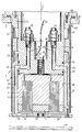
- the invention allows a wide variety of design options; one of them is shown schematically in more detail in the attached drawing, which shows the longitudinal section through the sputter cathode with screwed-on target and through a plane which has the cooling channels and the coolant connections.
- the cathode arranged opposite the substrate 46 essentially consists of a pot-shaped housing 3 formed from several parts, two permanent magnets 4, 5 held in the bottom of the pot-shaped housing 3, one of which has an annular cylindrical configuration and the other a circular cylindrical configuration, with one about circular cylindrical magnetic yoke 6, with the inserted in this circular cylindrical coil or electromagnet 61, a cup-shaped insert 8, which contains the connecting pieces 9, 10 for the cooling channels 11, 12 and the bore 56 for the connecting cable 60 for the electromagnet 61 and the can be locked on the housing 3 with the aid of not shown radially adjustable bolts.
- the pot-shaped housing 3 consists of a flange 23 for holding the cathode on the wall 30 of the process chamber, the two profile rings 24, 25, the ceramic ring 26 arranged between the two profile rings 24, 25, the water-cooled outer sleeve part 27, the soldered base plate 58, the target 29 and the soldered-in threaded sleeve 59.
- the bores 31, 31 ',... Penetrate the cylindrical body and connect the cooling circuit between the forward and the return in the cavity 32.
- These bores or cavities 31, 31 ', ... or 32 correspond to connection bores 33 or 34 which are provided in the insert 8 and which in turn are connected to the cooling channels 11, 12 which in turn are connected via the screw connections or connecting pieces 9 , 10 are connected to the coolant line 35, 36.
- the bore or opening 56 enables the installation of an electromagnet 61 with the associated magnetic yoke 6.
- the cathode described above has the advantage that the cooling jacket or the cavities 31, 31 ',... Or 32 through which the coolant flows are on the outside, while the coolant connections 9, 10 are on the inside, so that there is no leakage in the coolant supply line can lead to a coolant break-in in the process chamber 2.
- the coolant connections can also be easily removed from the screw connections or the connecting pieces 9, 10 without the process chamber 2 having to be ventilated.
- the magnet insert can be replaced when the process chamber 2 is evacuated, and the distance between the magnets 4, 5 and the target 29 can be changed without the process chamber 2 having to be opened or flooded.
- the insert 8 and the magnet set 4, 5, 6, 61 attached to it can also be removed from the cathode simply to the rear or to the top.
- the power supply 52 to the sleeve part 27 or to the target 29 takes place via the locking bolts mentioned above, which are held under prestress and pressed radially outwards (not shown in more detail), so that a secure current transfer between the locking bolts and the Sleeve 27 is guaranteed.
- the HF-resistant insert 8 is finally sealed with the aid of round cord rings (sealing rings) 50, 51 against the inner wall of the housing 3 in such a way that the coolant only from the connection bores 33, 34 into the cavity or intermediate space 32 or the bores 31 , 31 'can occur.
- the base plate 58 is vacuum-soldered to the cylindrical part 27 at all contact points.
- a threaded sleeve 59 is soldered to the base plate 58 for the purpose of central target attachment.
- the housing 3 of the cathode is enclosed by a tubular dark room shield 47 which is fastened to the flange 23 by means of a bayonet connection 57, and that the parts 23 and 24 or the parts 25 and 27 by welding and the parts 24 and 26 or 26 and 25 are connected to one another by brazing and that the flange 23 of the housing 3 is screwed to the collar of the insert 8 which extends radially outwards.
Landscapes
- Chemical & Material Sciences (AREA)
- Physics & Mathematics (AREA)
- Engineering & Computer Science (AREA)
- Plasma & Fusion (AREA)
- Analytical Chemistry (AREA)
- Chemical Kinetics & Catalysis (AREA)
- Materials Engineering (AREA)
- Mechanical Engineering (AREA)
- Metallurgy (AREA)
- Organic Chemistry (AREA)
- Electromagnetism (AREA)
- Physical Vapour Deposition (AREA)
Applications Claiming Priority (2)
| Application Number | Priority Date | Filing Date | Title |
|---|---|---|---|
| DE19914143135 DE4143135A1 (de) | 1991-11-14 | 1991-12-28 | Kathode zum beschichten eines substrats |
| DE4143135 | 1991-12-28 |
Publications (2)
| Publication Number | Publication Date |
|---|---|
| EP0549854A1 true EP0549854A1 (fr) | 1993-07-07 |
| EP0549854B1 EP0549854B1 (fr) | 1996-03-20 |
Family
ID=6448213
Family Applications (1)
| Application Number | Title | Priority Date | Filing Date |
|---|---|---|---|
| EP92111759A Expired - Lifetime EP0549854B1 (fr) | 1991-12-28 | 1992-07-10 | Cathode de revêtement d'un substrat |
Country Status (3)
| Country | Link |
|---|---|
| EP (1) | EP0549854B1 (fr) |
| DE (1) | DE59205763D1 (fr) |
| ES (1) | ES2084886T3 (fr) |
Cited By (6)
| Publication number | Priority date | Publication date | Assignee | Title |
|---|---|---|---|---|
| WO1995006954A1 (fr) * | 1993-08-30 | 1995-03-09 | W. Blösch AG | Cathode a champ magnetique |
| DE19525007A1 (de) * | 1995-03-09 | 1997-01-09 | Leybold Ag | Kathodenanordnung für eine Vorrichtung zum Zerstäuben eines Targets |
| US5683560A (en) * | 1995-07-08 | 1997-11-04 | Balzers Und Leybold Deutschland Holding Ag | Cathode assembly |
| US6264804B1 (en) | 2000-04-12 | 2001-07-24 | Ske Technology Corp. | System and method for handling and masking a substrate in a sputter deposition system |
| US6980390B2 (en) | 2003-02-05 | 2005-12-27 | Quantum Corporation | Magnetic media with embedded optical servo tracks |
| US7187515B2 (en) | 2003-02-05 | 2007-03-06 | Quantum Corporation | Method and system for tracking magnetic media with embedded optical servo tracks |
Families Citing this family (10)
| Publication number | Priority date | Publication date | Assignee | Title |
|---|---|---|---|---|
| US7153366B1 (en) | 1998-03-24 | 2006-12-26 | Quantum Corporation | Systems and method for forming a servo pattern on a magnetic tape |
| US7029726B1 (en) | 1999-07-27 | 2006-04-18 | Quantum Corporation | Method for forming a servo pattern on a magnetic tape |
| DE19913382C2 (de) | 1998-03-24 | 2002-08-14 | Quantum Corp | Mehrkanaliges Magnetbandsystem mit einem optischen Spur-Servo |
| JP4293733B2 (ja) | 1999-02-16 | 2009-07-08 | クウォンタム・コーポレイション | 磁気テープへのサーボ信号書き込み方法 |
| WO2000049605A1 (fr) | 1999-02-17 | 2000-08-24 | Quantum Corporation | Procede d'ecriture de signaux d'asservissement sur une bande magnetique |
| US6961200B2 (en) | 1999-07-27 | 2005-11-01 | Quantum Corporation | Optical servo track identification on tape storage media |
| US6558774B1 (en) | 1999-08-17 | 2003-05-06 | Quantum Corporation | Multiple-layer backcoating for magnetic tape |
| US6940676B1 (en) | 2000-06-07 | 2005-09-06 | Quantum Corporation | Triple push-pull optical tracking system |
| US6940681B2 (en) | 2001-08-20 | 2005-09-06 | Quantum Corporation | Optical to magnetic alignment in magnetic tape system |
| US7023650B2 (en) | 2001-11-07 | 2006-04-04 | Quantum Corporation | Optical sensor to recording head alignment |
Citations (3)
| Publication number | Priority date | Publication date | Assignee | Title |
|---|---|---|---|---|
| US4401539A (en) * | 1981-01-30 | 1983-08-30 | Hitachi, Ltd. | Sputtering cathode structure for sputtering apparatuses, method of controlling magnetic flux generated by said sputtering cathode structure, and method of forming films by use of said sputtering cathode structure |
| DE3727901A1 (de) * | 1987-08-21 | 1989-03-02 | Leybold Ag | Zerstaeubungskathode nach dem magnetronprinzip |
| EP0337012A2 (fr) * | 1988-04-14 | 1989-10-18 | Leybold Aktiengesellschaft | Cathode pour pulvérisation selon le principe magnétron |
Family Cites Families (1)
| Publication number | Priority date | Publication date | Assignee | Title |
|---|---|---|---|---|
| DE4137483A1 (de) * | 1991-11-14 | 1993-05-19 | Leybold Ag | Kathode zum beschichten eines substrats |
-
1992
- 1992-07-10 EP EP92111759A patent/EP0549854B1/fr not_active Expired - Lifetime
- 1992-07-10 DE DE59205763T patent/DE59205763D1/de not_active Expired - Fee Related
- 1992-07-10 ES ES92111759T patent/ES2084886T3/es not_active Expired - Lifetime
Patent Citations (3)
| Publication number | Priority date | Publication date | Assignee | Title |
|---|---|---|---|---|
| US4401539A (en) * | 1981-01-30 | 1983-08-30 | Hitachi, Ltd. | Sputtering cathode structure for sputtering apparatuses, method of controlling magnetic flux generated by said sputtering cathode structure, and method of forming films by use of said sputtering cathode structure |
| DE3727901A1 (de) * | 1987-08-21 | 1989-03-02 | Leybold Ag | Zerstaeubungskathode nach dem magnetronprinzip |
| EP0337012A2 (fr) * | 1988-04-14 | 1989-10-18 | Leybold Aktiengesellschaft | Cathode pour pulvérisation selon le principe magnétron |
Cited By (8)
| Publication number | Priority date | Publication date | Assignee | Title |
|---|---|---|---|---|
| WO1995006954A1 (fr) * | 1993-08-30 | 1995-03-09 | W. Blösch AG | Cathode a champ magnetique |
| US5861088A (en) * | 1993-08-30 | 1999-01-19 | W. Bloesch Ag | Magnetic field cathode |
| DE19525007A1 (de) * | 1995-03-09 | 1997-01-09 | Leybold Ag | Kathodenanordnung für eine Vorrichtung zum Zerstäuben eines Targets |
| US5683560A (en) * | 1995-07-08 | 1997-11-04 | Balzers Und Leybold Deutschland Holding Ag | Cathode assembly |
| US6264804B1 (en) | 2000-04-12 | 2001-07-24 | Ske Technology Corp. | System and method for handling and masking a substrate in a sputter deposition system |
| US6406598B2 (en) | 2000-04-12 | 2002-06-18 | Steag Hamatech Ag | System and method for transporting and sputter coating a substrate in a sputter deposition system |
| US6980390B2 (en) | 2003-02-05 | 2005-12-27 | Quantum Corporation | Magnetic media with embedded optical servo tracks |
| US7187515B2 (en) | 2003-02-05 | 2007-03-06 | Quantum Corporation | Method and system for tracking magnetic media with embedded optical servo tracks |
Also Published As
| Publication number | Publication date |
|---|---|
| DE59205763D1 (de) | 1996-04-25 |
| ES2084886T3 (es) | 1996-05-16 |
| EP0549854B1 (fr) | 1996-03-20 |
Similar Documents
| Publication | Publication Date | Title |
|---|---|---|
| EP0549854B1 (fr) | Cathode de revêtement d'un substrat | |
| DE69814687T2 (de) | Plasmavorrichtung mit einem mit einer spannungsquelle verbundenen metallteil, das zwischen einer rf-plasma-anregungsquelle und dem plasma angeordnet ist | |
| DE2102352C3 (de) | Hochfrequenzbetriebene Sprühvorrichtung | |
| DE4042287C2 (de) | Vorrichtung zum reaktiven Aufstäuben von elektrisch isolierendem Werkstoff | |
| US3836946A (en) | Coaxial connector | |
| DE2333221A1 (de) | Magnetron | |
| DE102012200564A1 (de) | Antriebs- und Versorgungseinrichtung für eine rotierende Elektrode, drehbare Anode und Vakuumprozessanlage | |
| DE4315023C2 (de) | Vorrichtung zur Kathodenzerstäubung | |
| DE4127260C1 (en) | Magnetron sputter source | |
| EP1273027B1 (fr) | Chambre de reaction dotee d'au moins une ouverture pour ligne h.f. | |
| EP0372179B1 (fr) | Réalisation pour procurer de l'énergie haute fréquence, ainsi que son utilisation | |
| US2490596A (en) | Shielded connection | |
| EP0541903B1 (fr) | Cathode pour revêtir un substrat | |
| DE4143135A1 (de) | Kathode zum beschichten eines substrats | |
| DE102013106168B4 (de) | Cantilever-Magnetron mit einem rotierenden Target | |
| DE2528032C2 (de) | Elektronenstrahlerzeuger für Heiz-, Schmelz- und Verdampfungszwecke | |
| EP0254168A2 (fr) | Cathode de pulvérisation pour dispositifs de dépôt sous vide | |
| US5482610A (en) | Cathode for coating a substrate | |
| DE2231627C3 (de) | Anschluß für die Signalplatte einer Fernsehaufnahmeröhre | |
| EP0257278B1 (fr) | Tube électronique à grille-écran, en particulier tétrode émettrice haute puissance et haute fréquence | |
| US3286021A (en) | Cable terminal for use with electron gun apparatus | |
| DE2608323A1 (de) | Anordnung zum zerstaeuben von festkoerpern im hochvakuum, insbesondere von dielektrischen stoffen in wechselspannungs- kathodenzerstaeubungs-anlagen | |
| DE4201211C2 (de) | Beschichtungsanlage | |
| US3012307A (en) | Printed circuit connector | |
| DE1614158A1 (de) | Kathode fuer Roentgenroehre |
Legal Events
| Date | Code | Title | Description |
|---|---|---|---|
| PUAI | Public reference made under article 153(3) epc to a published international application that has entered the european phase |
Free format text: ORIGINAL CODE: 0009012 |
|
| AK | Designated contracting states |
Kind code of ref document: A1 Designated state(s): CH DE ES FR GB IT LI |
|
| 17P | Request for examination filed |
Effective date: 19930721 |
|
| 17Q | First examination report despatched |
Effective date: 19950109 |
|
| GRAA | (expected) grant |
Free format text: ORIGINAL CODE: 0009210 |
|
| ITF | It: translation for a ep patent filed | ||
| AK | Designated contracting states |
Kind code of ref document: B1 Designated state(s): CH DE ES FR GB IT LI |
|
| REG | Reference to a national code |
Ref country code: CH Ref legal event code: NV Representative=s name: PATENTANWALTSBUERO FELDMANN AG |
|
| GBT | Gb: translation of ep patent filed (gb section 77(6)(a)/1977) |
Effective date: 19960320 |
|
| REF | Corresponds to: |
Ref document number: 59205763 Country of ref document: DE Date of ref document: 19960425 |
|
| REG | Reference to a national code |
Ref country code: ES Ref legal event code: FG2A Ref document number: 2084886 Country of ref document: ES Kind code of ref document: T3 |
|
| ET | Fr: translation filed | ||
| RAP2 | Party data changed (patent owner data changed or rights of a patent transferred) |
Owner name: BALZERS UND LEYBOLD DEUTSCHLAND HOLDING AKTIENGESE |
|
| ITPR | It: changes in ownership of a european patent |
Owner name: CAMBIO NOME EPO;BALZERS UND LEYBOLD DEUTSCHLAND HO |
|
| PLBE | No opposition filed within time limit |
Free format text: ORIGINAL CODE: 0009261 |
|
| STAA | Information on the status of an ep patent application or granted ep patent |
Free format text: STATUS: NO OPPOSITION FILED WITHIN TIME LIMIT |
|
| 26N | No opposition filed | ||
| PGFP | Annual fee paid to national office [announced via postgrant information from national office to epo] |
Ref country code: FR Payment date: 19980611 Year of fee payment: 7 |
|
| PGFP | Annual fee paid to national office [announced via postgrant information from national office to epo] |
Ref country code: GB Payment date: 19980623 Year of fee payment: 7 |
|
| PGFP | Annual fee paid to national office [announced via postgrant information from national office to epo] |
Ref country code: DE Payment date: 19980629 Year of fee payment: 7 |
|
| PGFP | Annual fee paid to national office [announced via postgrant information from national office to epo] |
Ref country code: CH Payment date: 19980701 Year of fee payment: 7 |
|
| PGFP | Annual fee paid to national office [announced via postgrant information from national office to epo] |
Ref country code: ES Payment date: 19980710 Year of fee payment: 7 |
|
| PG25 | Lapsed in a contracting state [announced via postgrant information from national office to epo] |
Ref country code: GB Free format text: LAPSE BECAUSE OF NON-PAYMENT OF DUE FEES Effective date: 19990710 |
|
| PG25 | Lapsed in a contracting state [announced via postgrant information from national office to epo] |
Ref country code: ES Free format text: LAPSE BECAUSE OF NON-PAYMENT OF DUE FEES Effective date: 19990711 |
|
| PG25 | Lapsed in a contracting state [announced via postgrant information from national office to epo] |
Ref country code: LI Free format text: LAPSE BECAUSE OF NON-PAYMENT OF DUE FEES Effective date: 19990731 Ref country code: FR Free format text: THE PATENT HAS BEEN ANNULLED BY A DECISION OF A NATIONAL AUTHORITY Effective date: 19990731 Ref country code: CH Free format text: LAPSE BECAUSE OF NON-PAYMENT OF DUE FEES Effective date: 19990731 |
|
| GBPC | Gb: european patent ceased through non-payment of renewal fee |
Effective date: 19990710 |
|
| REG | Reference to a national code |
Ref country code: CH Ref legal event code: PL |
|
| PG25 | Lapsed in a contracting state [announced via postgrant information from national office to epo] |
Ref country code: DE Free format text: LAPSE BECAUSE OF NON-PAYMENT OF DUE FEES Effective date: 20000503 |
|
| REG | Reference to a national code |
Ref country code: FR Ref legal event code: ST |
|
| REG | Reference to a national code |
Ref country code: ES Ref legal event code: FD2A Effective date: 20000810 |
|
| PG25 | Lapsed in a contracting state [announced via postgrant information from national office to epo] |
Ref country code: IT Free format text: LAPSE BECAUSE OF NON-PAYMENT OF DUE FEES;WARNING: LAPSES OF ITALIAN PATENTS WITH EFFECTIVE DATE BEFORE 2007 MAY HAVE OCCURRED AT ANY TIME BEFORE 2007. THE CORRECT EFFECTIVE DATE MAY BE DIFFERENT FROM THE ONE RECORDED. Effective date: 20050710 |