EP0549867A2 - Procédé et appareil à transfert direct d'images développées d'un tambour photoconductif sur un support d'impression - Google Patents
Procédé et appareil à transfert direct d'images développées d'un tambour photoconductif sur un support d'impression Download PDFInfo
- Publication number
- EP0549867A2 EP0549867A2 EP92118751A EP92118751A EP0549867A2 EP 0549867 A2 EP0549867 A2 EP 0549867A2 EP 92118751 A EP92118751 A EP 92118751A EP 92118751 A EP92118751 A EP 92118751A EP 0549867 A2 EP0549867 A2 EP 0549867A2
- Authority
- EP
- European Patent Office
- Prior art keywords
- photoconductive drum
- transfer roller
- direct transfer
- print medium
- increase
- Prior art date
- Legal status (The legal status is an assumption and is not a legal conclusion. Google has not performed a legal analysis and makes no representation as to the accuracy of the status listed.)
- Withdrawn
Links
Images

Classifications
-
- G—PHYSICS
- G03—PHOTOGRAPHY; CINEMATOGRAPHY; ANALOGOUS TECHNIQUES USING WAVES OTHER THAN OPTICAL WAVES; ELECTROGRAPHY; HOLOGRAPHY
- G03G—ELECTROGRAPHY; ELECTROPHOTOGRAPHY; MAGNETOGRAPHY
- G03G15/00—Apparatus for electrographic processes using a charge pattern
- G03G15/14—Apparatus for electrographic processes using a charge pattern for transferring a pattern to a second base
- G03G15/16—Apparatus for electrographic processes using a charge pattern for transferring a pattern to a second base of a toner pattern, e.g. a powder pattern, e.g. magnetic transfer
- G03G15/169—Apparatus for electrographic processes using a charge pattern for transferring a pattern to a second base of a toner pattern, e.g. a powder pattern, e.g. magnetic transfer with means for preconditioning the toner image before the transfer
-
- G—PHYSICS
- G03—PHOTOGRAPHY; CINEMATOGRAPHY; ANALOGOUS TECHNIQUES USING WAVES OTHER THAN OPTICAL WAVES; ELECTROGRAPHY; HOLOGRAPHY
- G03G—ELECTROGRAPHY; ELECTROPHOTOGRAPHY; MAGNETOGRAPHY
- G03G15/00—Apparatus for electrographic processes using a charge pattern
- G03G15/01—Apparatus for electrographic processes using a charge pattern for producing multicoloured copies
- G03G15/0105—Details of unit
- G03G15/0131—Details of unit for transferring a pattern to a second base
-
- G—PHYSICS
- G03—PHOTOGRAPHY; CINEMATOGRAPHY; ANALOGOUS TECHNIQUES USING WAVES OTHER THAN OPTICAL WAVES; ELECTROGRAPHY; HOLOGRAPHY
- G03G—ELECTROGRAPHY; ELECTROPHOTOGRAPHY; MAGNETOGRAPHY
- G03G15/00—Apparatus for electrographic processes using a charge pattern
- G03G15/14—Apparatus for electrographic processes using a charge pattern for transferring a pattern to a second base
- G03G15/16—Apparatus for electrographic processes using a charge pattern for transferring a pattern to a second base of a toner pattern, e.g. a powder pattern, e.g. magnetic transfer
- G03G15/1665—Apparatus for electrographic processes using a charge pattern for transferring a pattern to a second base of a toner pattern, e.g. a powder pattern, e.g. magnetic transfer by introducing the second base in the nip formed by the recording member and at least one transfer member, e.g. in combination with bias or heat
- G03G15/167—Apparatus for electrographic processes using a charge pattern for transferring a pattern to a second base of a toner pattern, e.g. a powder pattern, e.g. magnetic transfer by introducing the second base in the nip formed by the recording member and at least one transfer member, e.g. in combination with bias or heat at least one of the recording member or the transfer member being rotatable during the transfer
Definitions
- This invention relates generally to electrophotographic color printing and more particularly to such printing using the direct transfer of liquid toners to a print medium.
- liquid color toners in color image development processes is generally well known in the art of electrophotography and is described, for example, in U.S. Patent No. 4,286,039 issued to Landa et al, and in U.S. Patent No. 4,946,753 and U.S. Patent No. 4,925,766 both issued to Elmasry et al, all incorporated herein by reference.
- the general purpose and principal object of the present invention is to provide still further new and useful improvements in the art and technology of using color toners for directly transferring color images from the surface of a photoconductive drum onto an adjacent print medium.
- Another object of this invention is to provide a new and improved method and apparatus of the type described which is useful in optimizing the conditions under which the direct transfer of a color image from the surface of a photoconductive drum to an adjacent print media takes place in the location where the print media passes between and in intimate contact with the drum and a transfer roller.
- Another object of this invention is to provide a new and improved method and apparatus of the type described which is economical to manufacture, reliable in operation, and has a high price/performance figure of merit.
- Another object of this invention is to provide a new and improved method and apparatus of the type described which is operable to eliminate air ionization problems previously encountered with earlier developed direct transfer electrophotographic color printers.
- Another object of this invention is to provide a new and improved method and apparatus of the type described which serves to reduce electrical stresses on a photoconductive drum member of an electrophotographic printer, thereby in turn increasing the lifetime of the photoconductive drum.
- a novel feature of this invention is the provision of a new and improved method and apparatus of the type described wherein lower organic photoconductor (OPC) potentials are developed in the non-imaged OPC areas due to the overall illumination employed herein. This feature in turn helps prevent air ionization and other undesirable paper charging problems.
- OPC organic photoconductor
- the above novel operation thus has the effect of improving the fidelity and print quality of the composite color image which is transferred from the surface of the photoconductive drum onto the adjacent surface of the print medium which passes between the photoconductive drum and the adjacent biased transfer roller.
- Figure 1 is an abbreviated schematic diagram illustrating the electrophotographic color printer and method of operation according to the present invention.
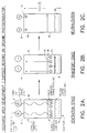
- FIGS 2A, 2B, and 2C illustrate the hole-electron pair charge neutralization process across the surface layer of the photoconductive drum member in Figure 1.
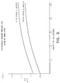
- Figure 3 is a graph of absolute electrostatic pressure,
- an organic photoconductive drum 10 which is positioned adjacent to a source 12 of monochromatic (e.g. laser) light 14 used for developing color images on the surface of the drum 10.
- the apparatus in Figure 1 further includes a conventional corona charge mechanism 16 for the drum 10 and a conventional drum surface cleaning apparatus 18 mounted as shown adjacent to the surface of the photoconductive drum 10.
- Cyan, yellow, magenta, and black color liquid toner sources 20, 22, 24, and 26 are located as shown adjacent to the lower surface of the photoconductive drum 10, and these color and black sources of transparent liquid toner are constructed and operated in a well known manner understood by those skilled in the electrophotographic color printing arts and are therefor not described in any significant detail herein.
- Cyan, yellow, magenta, and black color liquid toner sources 20, 22, 24, and 26 are located as shown adjacent to the lower surface of the photoconductive drum 10, and these color and black sources of transparent liquid toner are constructed and operated in a well known manner understood by those skilled in the electrophotographic color printing arts and are therefor not described in any significant detail herein.
- a heated and electrically biased transfer roller is designated generally as 28 and is rotatably mounted as shown above the upper surface of the photoconductive drum 10.
- the transfer roller 28 is operative to be driven against the upper surface of a print medium 30, such as paper, which passes between the outer surface of the transfer roller 28 and the outer surface of the organic photoconductive drum 10.
- the transfer roller 28 is constructed and operated in accordance with the principles and teachings in the above identified co-pending application Serial No. 07/704,572, filed in May 17, 1991, and will include a conductive inner core member 32 within which a heater element 34 is located.
- the conductive inner core or metal sleeve member 32 is surrounded at its outer surface by a first cylindrically formed elastomer layer 36 which in turn is coated by a thin outer protective coating 38.
- the metal inner core member 32 is connected by way of a conductor 40 to a source 42 of electrical bias, the other side of which is grounded at node 44.
- a cylindrical air gap 45 separates the centrally located heater element 34 from the inner metal sleeve 38, and the heater element which is positioned at the axis of rotation of the transfer roller 28 will preferably be an elongated quartz heater tube.
- This heater tube will typically be heated during an image transfer operation to a controlled elevated temperature on the order of 80 - 90°C or greater to provide the thermal energy in combination with electrical and mechanical forces in the nip zone of the transfer roller 28 which makes direct contact with the media 30.
- the inner metal sleeve 32 will be DC biased to a voltage in excess of minus 900 volts DC, and a mechanical pressure will also be applied to the nip zone at a level on the order of five (5) psi or greater.
- a liquid toner conditioning and stabilizing apparatus is indicated generally as 46 and is located as shown on the right hand side of the photoconductive drum 10.
- This toner conditioning apparatus 46 is operatively driven by a drive motor 48 and drive belt 50 in intimate contact with the outer surface of the photoconductive drum 10.
- the toner conditioning and stabilizing apparatus 46 also includes a centrally disposed heating element 52 which is surrounded first by a cylindrical air gap 54 and then by an inner metal roller core 56 of a suitable metal such as aluminum.
- the heating element 52 may also be an elongated quartz tube positioned at the rotational axis of the conditioning roller 46.
- the roller core member 56 is surrounded by a metal slip ring 58 which is in turn connected through a bias electrode 60 and an interconnect pin 62 within the adjacent housing 64 to source 66 of DC bias, the other side of which is grounded at node 68.
- the outer surface of the metal slip ring 58 is surrounded by a soft core elastomer material 70 having a very smooth outer surface 72 which is required in the toner conditioning operation to be described below.
- the outer core member 70 may for example be a conductive silicone or a conductive polyurethane material. The reason that the soft core material 70 appears discontinuous in the figures is that the elements 60, 62, and 64 of the biasing arrangement for the slip ring 58 are located in front of the soft core roller 70.
- the heated and biased transfer roller 28 and media 30 are initially moved away from the surface of the organic photoconductive drum 10 during the exposure and development process used for developing layers of cyan, yellow, magenta, and black transparent color toners, one on top of another, on the surface of the photoconductive drum 10.
- the toner conditioning apparatus 46 on the right hand side of the drum 10 and then subsequently exposed by light 14 from the monochromatic light source 12 on the left hand side of the photoconductive drum 10.
- the heated and biased transfer roller 28 and print medium 30 are then brought into intimate contact in the position shown in Figure 1 with the surface of the photoconductive drum 10.
- the composite developed color image is transferred to the lower surface of the print medium 30 as a unitary and cohesive polymeric film which holds tightly together all of the developed color toners.
- these color toners would be transferred in discrete particle form front the surface of the photoconductive drum 10 to the underside of the print medium 30.
- Each of the sources of color liquid transparent toners 20, 22, 24, and 26 includes a combination of positively charged toner particles which are immersed in a charged isopar toner carrier liquid.
- the positively charged surface of the photoconductive drum 10 rotates past these liquid toner sources 20, 22, 24, and 26, the positively charged toner particles are electrostatically pulled onto the surface of the photoconductive drum 10, while simultaneously the negatively charged counter ions are stripped away from their positively charged nuclei and onto an adjacent positively charged substrate (not shown).
- some of the carrier liquid is pulled onto the surface of the photoconductive drum 10 along with the positively charged toner particles which it surrounds and therefore needs to be conditioned and stabilized in order to develop the color-on-color layers of toner into a cohesive and unitary polymeric film. This is accomplished by operation of the toner conditioning and stabilizing apparatus 46 as shown on the right hand side of Figure 1 and in the enlarged cross section view in Figure 2.
- the toner conditioning apparatus 46 is operative to provide a combination of mechanical pressure, electrostatic forces, and a low level of thermal energy to the successive layers of liquid toner as they pass in succession counterclockwise against the smooth surface 72 of the outer conditioning soft core roller member 70.
- the outer roller member 70 is preferably a soft elastomeric material such as a polyurethane or conductive silicone material having a volume resistivity less than about 108 ohm ⁇ centimeters and a Shore A Hardness less than 30.
- the soft elastomeric roller 70 outer cover layer must be designed to have a smooth surface finish which is useful to preserve the fidelity of images and must also be blade cleaned to remove excess carrier fluid therefrom.
- the inner core 56 of the toner conditioning apparatus 46 is a cylindrical metal sleeve such as aluminum and biased to a maximum allowable DC potential of the same polarity as that of the liquid toner particles. This feature is useful in order to provide a recharging of any electrically discharged toner particles which will naturally take place during the operation of the above color toner development process. Both DC and AC bias may be used on conductor 62 to provide the proper sign and level of toner charge for the efficient transfer of the developed polymeric film on the outer surface of the photoconductive drum 10 directly onto the undersurface of the print medium 30.
- a novel electrophotographic color printing and toner conditioning apparatus 46 which is operative in an efficient manner to properly prepare developed transparent color liquid toners for direct transfer to a receiving sheet of paper.
- the electrically biased and heated conditioning roller 46 which is in intimate contact with the surface of the photoconductive drum 10 compresses the charged toner particles thereon which are received by the conditioning apparatus 46 in discrete particle form.
- This electrostatic and mechanical compression by the toner conditioning apparatus 46 of the multiple and serially deposited discrete particle films operates to preserve the fidelity of the images superimposed one upon another, and it also helps prevent degradation of these images. Such degradation may otherwise take the form of poor edge acuity around printed characters, streaks, and general toner scattering.
- the biased and heated roller conditioning apparatus 46 will also serve to apply the proper toner charge level and polarity in the case where toners become charge deficient as indicated above.
- This toner conditioning apparatus 46 is also used to reduce and limit undesirable amounts of liquid carrier (e.g. isopar) that is normally carried out onto the print medium due to its presence on the photoconductor in both image and background regions.
- This isopar fluid is significantly removed by the conditioning apparatus 46 whose smooth outer surface 72 is continuously cleaned by the wiping action of the cleaning blade 74 as previously described to scrape away residual isopar from the surface 72 of the conditioning roller 46.
- Optimum cleaning is achieved by the use of a sharp cleaning blade 74 which brushes in intimate contact with the smooth surface 72 of the roller member 46 thereby enabling the isopar excess liquid to be collected in an adjacent container (not shown).
- a photoconductor illuminator 76 such as a light emitting diode (LED) array is positioned approximately a distance of two (2) millimeters from the surface of the organic photoconductor 10 and is designed to give off a light wavelength in the vicinity of 840 nanometers. This wavelength is in the wavelength range corresponding to the wavelength range characteristic of the organic photoconductor substrate region, its charge generation layer which is disposed on the surface of the substrate region, and its charge transport layer which is disposed on the surface of the charged generation layer as indicated in more detail in Figures 2A through 2C below.
- the power level of the LED array should be about 3500 miliwatts per centimeter squared or greater.
- the substrate region 78 of the organic photoconductor 10 will retain a negative charge 80 after the photoconductor 10 receives a latent image generated by a laser beam. This process attracts a positive toner charge 82 to the surface 84 of a charge transport layer 86 due to the electrostatic fields present, and also produces photogenerated charged hole-electron pairs 88 within a charge generation layer 90.
- the photogenerated charge pairs 88 in the intermediate charge generation layer 90 will remain in the position as indicated in Figure 2A and, in the absence of applying light from the photoconductor illuminator 76, would otherwise represent the charge condition at the surface of the organic photoconductor 10 during transfer of the developed image onto the print media 30.
- the application of light from the photoconductor illuminator 76 to the surface of the photoconductor 10 produces the charge transport stage condition in the various layers of the photoconductive drum 10 as shown in Figure 2B.
- the incident light received at the surface 84 of the charge transport layer 86 causes the negative charges 92 in the charge generation layer 90 to be accelerated toward the surface 84 of the charge transport layer 86 and thereby tends to neutralize and reduce the amount of total positive charge that now exists at the surface 84 of the charge transport layer 86.
- Figure 2C represents the condition where the region 98 therein is almost completely neutralized, the charge generation layer 90 is substantially neutralized, and only a small amount of negative charge 100 is left beneath the surface 84 of the charge transport layer 86.
- This neutralization effect thus leaves a substantially reduced net positive charge density atop the surface 84 of the charge transport layer 86 as shown in Figure 2C.
- the net effect of this action will be a reduced positive photoconductor potential which will ultimately allow a higher transfer biased to be applied to the transfer roller, thus creating a higher electrostatic transfer pressure.
- FIG 2A the charge generation stage is represented where charged hole-electron pairs are generated due to light impinging on the surface of the photoconductive drum 10.
- FIG 2B the charged pairs split and migrate toward opposite-signed surface and substrate charge densities.
- Figure 3C there is represented the final stage of charge neutralization where the potential on the surface of the photoconductive drum is near zero. This process takes place in both imaged (toner bearing) regions as well as in the background or unexposed regions.
- the organic photoconductor 10 is comprised of a substrate material upon which a thin barrier/sub-layer 78 is formed to a thickness of about 0.1 microns, and the charge generation layer 90 is formed on the surface of this barrier/sub-layer 78, also to a thickness of about 0.1 microns.
- the charge transport layer 86 is formed on the surface of the charge generation layer 90 to a thickness on the order of about 10 microns, and the transmittance versus wavelength characteristic for this composite layered structure peaks in the vicinity of 840 nanometers.
- this figure presents a calculation of the electrostatic pressure pulling a typical liquid toner film from the photoconductor to the paper both with and without the overall illumination at 76 shown in Figure 1.
- the lower curve in Figure 3 shows the toner transfer pressure for a photoconductor that has not been overall exposed and illuminated and has an image potential which was measured at about +100 volts.
- the upper curve in Figure 3 shows the same type of plot, but with the image potential measured at about +30 volts as a result of the overall illumination exposure made in accordance with the present invention.
- a comparison of the upper and lower plots in Figure 3 indicates about a 20% improvement in the electrostatic transfer pressures in the upper plot, since the lower photoconductor potentials provided by the present invention allow a higher bias to be used across the print media during image transfer without exceeding the critical levels which cause air ionization and disruptive toner affects.
- This higher bias in turn, produces an improved transfer efficiency of the developed image from the surface of the photoconductive drum 10 to the print media 30, thereby resulting in an improved print quality of color images on the print media and a higher fidelity of the transferred color images.
- the present invention is not limited to the use of an LED array for the illuminator 76 and other light sources such as quartz lamps, electroluminescent strips and the like which match to wavelength range of the photoconductive material layers of the photoconductor and have a sufficient power level to obtain adequate electron discharge at the surface of the photoconductor 10 may also be used herein.
- the present invention is not limited by the particular materials or geometric configuration of the conditioning roller described herein, and this toner stabilizing roller 46 may be used in combination with many different types of electrophotographic writing schemes, color toner transferring techniques for applying toner to the photoconductive drum and with various different additional schemes for aiding in the direct transfer of the developed color toners from the surface of the photoconductive drum to an adjacent print media.
- this toner stabilizing roller 46 may be used in combination with many different types of electrophotographic writing schemes, color toner transferring techniques for applying toner to the photoconductive drum and with various different additional schemes for aiding in the direct transfer of the developed color toners from the surface of the photoconductive drum to an adjacent print media.
- the present invention is not limited to use with the particular transfer roller apparatus 28 described herein. Accordingly, these and other design modifications are clearly within the scope of the following appended claims.
Landscapes
- Physics & Mathematics (AREA)
- General Physics & Mathematics (AREA)
- Electrostatic Charge, Transfer And Separation In Electrography (AREA)
- Color Electrophotography (AREA)
- Wet Developing In Electrophotography (AREA)
Applications Claiming Priority (2)
| Application Number | Priority Date | Filing Date | Title |
|---|---|---|---|
| US802028 | 1985-11-25 | ||
| US80202891A | 1991-12-03 | 1991-12-03 |
Publications (2)
| Publication Number | Publication Date |
|---|---|
| EP0549867A2 true EP0549867A2 (fr) | 1993-07-07 |
| EP0549867A3 EP0549867A3 (en) | 1994-07-20 |
Family
ID=25182660
Family Applications (1)
| Application Number | Title | Priority Date | Filing Date |
|---|---|---|---|
| EP19920118751 Withdrawn EP0549867A3 (en) | 1991-12-03 | 1992-11-02 | Method and apparatus for directly transferring developed images from a photoconductive drum to a print medium |
Country Status (2)
| Country | Link |
|---|---|
| EP (1) | EP0549867A3 (fr) |
| JP (1) | JPH05265336A (fr) |
Cited By (7)
| Publication number | Priority date | Publication date | Assignee | Title |
|---|---|---|---|---|
| US5650253A (en) * | 1995-09-29 | 1997-07-22 | Minnesota Mining And Manufacturing Company | Method and apparatus having improved image transfer characteristics for producing an image on a receptor medium such as a plain paper |
| EP0666519A3 (fr) * | 1994-02-08 | 1997-09-10 | Mita Industrial Co Ltd | Appareil de formation d'images utilisant un système de développement en inversion. |
| US5916718A (en) * | 1995-09-29 | 1999-06-29 | Imation Corp. | Method and apparatus for producing a multi-colored image in an electrophotographic system |
| US7592117B2 (en) | 2005-06-16 | 2009-09-22 | Hewlett-Packard Development Company, L.P. | System and method for transferring features to a substrate |
| US7920810B2 (en) | 2007-08-15 | 2011-04-05 | Hewlett-Packard Development Company, L.P. | Electrophotography device with electric field applicator |
| JP2016153853A (ja) * | 2015-02-20 | 2016-08-25 | 京セラドキュメントソリューションズ株式会社 | 画像形成装置 |
| CN111722503A (zh) * | 2019-03-19 | 2020-09-29 | 富士施乐株式会社 | 图像形成装置 |
Family Cites Families (3)
| Publication number | Priority date | Publication date | Assignee | Title |
|---|---|---|---|---|
| JPS62238585A (ja) * | 1986-04-09 | 1987-10-19 | Asahi Optical Co Ltd | 電子写真法による多色画像形成方法 |
| JPS63314579A (ja) * | 1987-06-18 | 1988-12-22 | Canon Inc | 画像形成装置 |
| JPS6413578A (en) * | 1987-07-08 | 1989-01-18 | Minolta Camera Kk | Destaticizer for electrophotographic device |
-
1992
- 1992-11-02 EP EP19920118751 patent/EP0549867A3/en not_active Withdrawn
- 1992-12-03 JP JP4350302A patent/JPH05265336A/ja active Pending
Cited By (9)
| Publication number | Priority date | Publication date | Assignee | Title |
|---|---|---|---|---|
| EP0666519A3 (fr) * | 1994-02-08 | 1997-09-10 | Mita Industrial Co Ltd | Appareil de formation d'images utilisant un système de développement en inversion. |
| US5650253A (en) * | 1995-09-29 | 1997-07-22 | Minnesota Mining And Manufacturing Company | Method and apparatus having improved image transfer characteristics for producing an image on a receptor medium such as a plain paper |
| US5916718A (en) * | 1995-09-29 | 1999-06-29 | Imation Corp. | Method and apparatus for producing a multi-colored image in an electrophotographic system |
| US7592117B2 (en) | 2005-06-16 | 2009-09-22 | Hewlett-Packard Development Company, L.P. | System and method for transferring features to a substrate |
| US7773916B2 (en) | 2005-06-16 | 2010-08-10 | Hewlett-Packard Development Company, L.P. | System and method for transferring features to a substrate |
| US7920810B2 (en) | 2007-08-15 | 2011-04-05 | Hewlett-Packard Development Company, L.P. | Electrophotography device with electric field applicator |
| JP2016153853A (ja) * | 2015-02-20 | 2016-08-25 | 京セラドキュメントソリューションズ株式会社 | 画像形成装置 |
| CN111722503A (zh) * | 2019-03-19 | 2020-09-29 | 富士施乐株式会社 | 图像形成装置 |
| CN111722503B (zh) * | 2019-03-19 | 2024-03-08 | 富士胶片商业创新有限公司 | 图像形成装置 |
Also Published As
| Publication number | Publication date |
|---|---|
| EP0549867A3 (en) | 1994-07-20 |
| JPH05265336A (ja) | 1993-10-15 |
Similar Documents
| Publication | Publication Date | Title |
|---|---|---|
| US5136334A (en) | Method and apparatus for preparing liquid tone for direct transfer to the media during electrophotographic printing | |
| US5280326A (en) | Imaging system | |
| EP0513819A2 (fr) | Rouleau et méthode de transfert assisté électrostatiquement pour le transfert direct de toner liquide sur un support d'impression | |
| US5291251A (en) | Image development and transfer apparatus which utilized an intermediate transfer film | |
| EP0549867A2 (fr) | Procédé et appareil à transfert direct d'images développées d'un tambour photoconductif sur un support d'impression | |
| JPS62118372A (ja) | 現像装置 | |
| EP0718718A1 (fr) | Appareil et procede d'enregistrement | |
| EP0513820A2 (fr) | Rouleau de conditionnement et méthode d'utilisation pour un tambour photoconducteur dans une imprimante électrophotographique couleur | |
| JP3417111B2 (ja) | カラー画像形成装置 | |
| CN1323334C (zh) | 成像装置 | |
| US6097920A (en) | Recording apparatus and method including intermediate transfer medium | |
| JPH0675484A (ja) | カラー画像形成装置 | |
| JP3702523B2 (ja) | 液体現像剤を用いた現像装置 | |
| JPH09211993A (ja) | 液体現像剤を用いた現像装置 | |
| JP3373655B2 (ja) | 画像形成装置 | |
| US6223011B1 (en) | Printing machine with reconditioning light source | |
| JP3517090B2 (ja) | 画像形成装置 | |
| JPH09185266A (ja) | 液体現像剤を用いた現像装置 | |
| JP3434071B2 (ja) | 画像形成装置の転写装置 | |
| JPH09185265A (ja) | 液体現像剤を用いた現像装置 | |
| JPH07121081A (ja) | 画像形成装置 | |
| EP0848305A2 (fr) | Appareil et méthode de formation d'images utilisant un développateur liquide | |
| JP3878752B2 (ja) | 画像形成装置 | |
| JPH05204265A (ja) | 電子写真式カラー印刷方法および装置 | |
| JPH05341670A (ja) | 中間転写装置 |
Legal Events
| Date | Code | Title | Description |
|---|---|---|---|
| PUAI | Public reference made under article 153(3) epc to a published international application that has entered the european phase |
Free format text: ORIGINAL CODE: 0009012 |
|
| AK | Designated contracting states |
Kind code of ref document: A2 Designated state(s): DE FR GB IT |
|
| PUAL | Search report despatched |
Free format text: ORIGINAL CODE: 0009013 |
|
| AK | Designated contracting states |
Kind code of ref document: A3 Designated state(s): DE FR GB IT |
|
| STAA | Information on the status of an ep patent application or granted ep patent |
Free format text: STATUS: THE APPLICATION IS DEEMED TO BE WITHDRAWN |
|
| 18D | Application deemed to be withdrawn |
Effective date: 19950121 |