EP0549910B1 - Régulateur de vitesse d'une turbine dentale - Google Patents
Régulateur de vitesse d'une turbine dentale Download PDFInfo
- Publication number
- EP0549910B1 EP0549910B1 EP92120578A EP92120578A EP0549910B1 EP 0549910 B1 EP0549910 B1 EP 0549910B1 EP 92120578 A EP92120578 A EP 92120578A EP 92120578 A EP92120578 A EP 92120578A EP 0549910 B1 EP0549910 B1 EP 0549910B1
- Authority
- EP
- European Patent Office
- Prior art keywords
- turbine wheel
- stream
- turbine
- dental
- speed
- Prior art date
- Legal status (The legal status is an assumption and is not a legal conclusion. Google has not performed a legal analysis and makes no representation as to the accuracy of the status listed.)
- Expired - Lifetime
Links
Images



Classifications
-
- A—HUMAN NECESSITIES
- A61—MEDICAL OR VETERINARY SCIENCE; HYGIENE
- A61C—DENTISTRY; APPARATUS OR METHODS FOR ORAL OR DENTAL HYGIENE
- A61C1/00—Dental machines for boring or cutting ; General features of dental machines or apparatus, e.g. hand-piece design
- A61C1/02—Dental machines for boring or cutting ; General features of dental machines or apparatus, e.g. hand-piece design characterised by the drive of the dental tools
- A61C1/05—Dental machines for boring or cutting ; General features of dental machines or apparatus, e.g. hand-piece design characterised by the drive of the dental tools with turbine drive
-
- Y—GENERAL TAGGING OF NEW TECHNOLOGICAL DEVELOPMENTS; GENERAL TAGGING OF CROSS-SECTIONAL TECHNOLOGIES SPANNING OVER SEVERAL SECTIONS OF THE IPC; TECHNICAL SUBJECTS COVERED BY FORMER USPC CROSS-REFERENCE ART COLLECTIONS [XRACs] AND DIGESTS
- Y10—TECHNICAL SUBJECTS COVERED BY FORMER USPC
- Y10S—TECHNICAL SUBJECTS COVERED BY FORMER USPC CROSS-REFERENCE ART COLLECTIONS [XRACs] AND DIGESTS
- Y10S415/00—Rotary kinetic fluid motors or pumps
- Y10S415/904—Tool drive turbine, e.g. dental drill
Definitions
- a dental turbine in which, as stated in the preamble of claim 1, regulating means are provided for regulating the speed, is known from US Pat. No. 3,775,851.
- Dental turbines have the advantage of a relatively simple structure and simple supply, but they have the disadvantages of a relatively low drilling capacity and an excessively high idling speed, which drops significantly when an external moment M is applied. Another consequence of the too high speed is a relatively high wear and the risk of burning tooth substance.
- Electric or air motor drives deliver sufficient torques and drilling performance;
- the optimal speeds (180 - 200,000 min ⁇ 1) can only be achieved with considerable technical effort (many fast moving parts) with correspondingly high wear, relatively high weight and relatively high costs.
- the regulation of the supply air flow can take place in the known turbine in various ways, inter alia via a spring-loaded slide in the return air duct, which controls the valve in the supply air duct, or via a membrane pressure cell arranged in the return air duct, which controls the flow in the supply line Piston adjusted.
- the well-known turbine is among others with the disadvantage that relatively large forces are required to throttle the entire air flow, which can only be applied in the exhaust air duct using volume and mass. This creates an unstable control behavior of the turbine. Furthermore, the known arrangement requires a relatively large structure within the turbine handpiece, which can lead to installation problems.
- a dental handpiece with a compressed air drive in which the speed can also be controlled by changing the volume flow rate of the return air.
- a hand-adjustable collar is arranged on the hose-side end of the handpiece, with which the cross section of the return air emerging can be changed.
- the handpiece is also provided with means for reversing the direction of rotation.
- a pin connected to the compressed air supply line which contains the air outlet nozzle directed towards the impeller blades, can be rotated relative to the impeller housing, so that the air outlet nozzle on the one hand on the front sides and on the other hand on the rear sides the impeller blades can be directed. Automatic control of the speed is not possible with this handpiece.
- the invention specified in claim 1 is based on the object of specifying a speed-controlled dental turbine which combines the positive properties of a turbine on the one hand and a motor drive on the other and avoids the disadvantages of the known controllable dental turbines.
- An essential characteristic of the control system according to claim 1 is that the volume flow of the drive fluid remains essentially constant, so that there is no throttling point that significantly influences the flow of the fluid neither in the supply line nor in the exhaust air line.
- a flexible part can be arranged in the immediate vicinity of the blade surfaces of the impeller, which is provided with an impact surface, to which a volume flow deflected on the impeller is directed in its effect depending on the speed.
- the speed control can be self-regulating or with the help of a sensor via a target / actual comparison.
- the speed (n) of the impeller is detected with a suitable sensor and the instantaneous speed is compared in a controller with a set target value (n s ).
- the controller influences, via an actuator, actuating means which will be described later in more detail and which affects the volume flow of the propellant air jet which emerges from the nozzle and impinges on the impeller, so that a speed deviation up to the maximum possible load P max remains as constant or very small as possible .
- the control of the speed to a desired value of the desired optimal speed is advantageously done in the following way:
- the turbine flows against the drive fluid and sets it in rotation.
- the driving jet is only changed in the immediate vicinity of the turbine impeller. The immediate proximity, therefore, to keep dead times short and to eliminate the influence of the compressibility of the air and possibly of elastic supply lines, which would lead to unstable control behavior or delayed adjustment to drill load changes.
- the jet guidance can advantageously be varied by means of a deflection flag between the nozzle opening and the impeller by means of a beam splitter in the region of the nozzle outlet opening, by axially displacing the impeller or by changing the nozzle position relative to the impeller.
- FIG. 1 shows a simplified basic illustration of a control arrangement for an indirect control of the rotational speed with the inclusion of a sensor and a controller with a comparison of the target and actual values.
- a dental turbine handpiece constructed in a known manner contains a turbine which is driven with a suitable fluid from a supply source 1 via a line 2. Since compressed air is the commonly used drive medium today, this is always assumed in the following. It is also conceivable and within the scope of the invention to use another suitable drive medium.
- the air flowing out of a nozzle 3 acts directly on the blades of the turbine impeller 4 in a manner known per se.
- the speed of the impeller 4 is detected with a suitable sensor 5.
- Controller 6 compares the current speed with an adjustable setpoint n s .
- the controller 6 activates an actuator 9 for generally designated 7 actuating means 7, which are explained in more detail in the following exemplary embodiments and which influence the propellant air jet (volume flow) indicated by arrow 8 and directed toward the impeller 4, in such a way that the speed deviation remains as small as possible up to a maximum possible load (P max ).
- the setpoint value is expediently at the optimum working speed of the turbine.
- FIG. 2 shows this constancy very clearly based on the characteristics of an uncontrolled turbine according to the prior art (characteristic I) and a regulated turbine according to the invention (characteristic II).
- the effect of the air flow 8 from the nozzle 3 on the impeller 4 can be influenced by an electromagnetic system comprising a magnetic coil 10 with a soft iron core 11, soft iron yoke 12 and an anchor plate 14 arranged on a spiral spring 13 in that an angled section of the spiral spring 13 to be referred to as a deflection flag 15 is drawn between the nozzle opening and the impeller 4.
- FIG. 3 shows the one end position of the deflection flag 15 when the coil is fully activated, at which the desired idling speed by partially shading the nozzle opening 3 and deflecting the emerging air jet 8.
- FIG. 4 shows the other end position of the deflection flag 15 at maximum load (P max ) on the turbine.
- the coil current is switched off.
- the deflection lug 15 is withdrawn from the nozzle opening by the spring force of the spiral spring 13.
- the drive beam is optimal here, i.e. aimed at the impeller with maximum efficiency.
- Various coil controls can be selected for speed control between idling and maximum load (P max ).
- the deflection flag 15 can advantageously be drawn more or less far in front of the nozzle opening by means of a variable coil current against the restoring force of the spiral spring 13.
- the regulation can be done by changing the clock ratio.
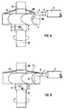
- the beam guidance is also influenced by a deflection flag 15. Unlike in Example 1, however, the proportion of the air flow 8 that strikes the impeller 4 is changed here. While in one end position (FIG. 5), which corresponds to a desired idling speed, only portion 8a is effectively directed towards the blades of the impeller, while the remaining portion 8b is largely not used, in the other end position (FIG. 6), which corresponds to the speed at maximum load, the full air flow 8 onto the paddle wheel.
- a piezoelectric bending beam 16 is used as an actuator for the deflection flag 15, which bends under the influence of an applied electrical voltage (U) in such a way that the position of the deflection flag 15 changes in the air jet.
- U an applied electrical voltage
- the control voltage U can be varied analog or digital.
- a line 17 branches off from the supply line 2, in which a valve 18 is arranged as an actuator.
- the outlet nozzle 19 of the branch line 17 is directed to a leaf spring 20.
- the air jet 8 from the outlet nozzle 3 is influenced by the deflection flag 15 fastened to the leaf spring 20, similarly as already described with reference to Example 1.
- the valve 18 can expediently be a solenoid valve which is activated by the controller 6 according to FIG. 1.
- the required solenoid valve 18 can also be kept correspondingly small.
- the auxiliary air flow can also be influenced with an electromagnetic or piezoelectric actuator with a deflection lug between the auxiliary nozzle opening and the leaf spring.
- a beam splitter 22 is provided in the air outlet nozzle 3.
- the cross section of the outlet nozzle opening can be changed so that either the entire volume flow 8 is passed through the outlet opening 24 (FIG. 9) or that the volume flow 8 is divided into variable partial flows (8a, 8b), one of which Partial flow (8a) acts as the drive current and the other, which exits via a nozzle opening 25 which is formed during adjustment, acts as the braking current (FIG. 10).
- FIG. 9 thus shows the beam splitter 22 which is movable for changing the cross section of the nozzle openings 24, 25 in the one end position in which the drive nozzle 24 has the maximum possible cross section.
- the brake nozzle 25 is completely closed (full load position P max ).
- Figure 10 shows the beam splitter 22 in the other end position.
- the drive nozzle cross section 24 is reduced here, while the brake nozzle 25 is open (idle position).
- Examples 1 to 3 can be provided as actuators for the beam splitter 22.
- This exemplary embodiment shows a possible embodiment of a self-regulating turbine.
- the deflecting vane 15, which acts as an adjusting means for changing the effect of the volume flow, is located on an annular spiral spring 26, which is arranged concentrically below the impeller 4 on a support 28 and serves as an actuator for the deflecting vane 15.
- FIG. 11 shows how the air flow 8 is deflected by the deflection vane 15 and divided into partial air flows 8a, 8b.
- the impeller 4 does not offer any appreciable flow resistance and runs freely with the current that is still incident.
- the idling speed is reduced to the desired level by the engagement of the deflection flag 15 in the jet guidance of the propellant air.
- Figure 12 shows the end position at full load (P max ) again.
- the driving air nozzle 3 is completely free here, as a result of which the driving air jet 8 is optimally directed onto the impeller 4.
- the control characteristic, the characteristic curve and / or the spring characteristic of the spiral spring mentioned above can be changed.
- the characteristic curve can be changed by appropriately designing the jet deflecting part or also the nozzle outlet opening.
- the nozzle opening can, for example, have a circular cross section receive a different cross-section.
- the spiral spring can also be coupled with suitable damping elements.
- spiral spring 26 forms only a section of a circular ring and is only clamped in the hatched area designated by 27 on a correspondingly designed carrier 28 (turbine housing).
- a partial disk 29 can be arranged between the impeller 4 and the spiral spring.
- Such a indexing disk serves as a shield against a possibly occurring suction effect between the paddle wheel and the spiral spring in this area.
- the spiral spring 26 can be provided with a damping element, for example by a vibration-damping film or the like is applied to the spring.
- the principle explained on the basis of exemplary embodiment 5 offers to direct the air flow deflected on the impeller onto the impact surface of an actuator or actuator, and to direct its effect as a function of the speed , the possibility so that the volume flow through eg to control a throttle or the like arranged in the supply line.
- FIGS. 14 and 15 Another embodiment of a self-regulating turbine is shown in FIGS. 14 and 15.
- the impeller 4 is freely movable on the shaft designated 30.
- the play is limited by an oblique groove 31 in the impeller collar and a driving pin 32 guided in the groove and firmly connected to the shaft.
- a plate spring 33 which is arranged concentrically above the impeller and is supported on a shaft collar 34, presses the impeller axially downward.
- FIG. 14 shows how the impeller is pressed into the lowest end position by the spring when idling, as a result of which the drive air jet 8 from the nozzle 3 is divided into partial streams 8a and 8b, partial stream 8b partly. flows ineffectively over the impeller.
- the drive blades do not offer any flow resistance and circulate freely with the remaining impinging air flow 8a at a reduced speed.
- Figure 15 shows the impeller position at maximum load (P max ) on the drive shaft.
- P max maximum load
- FIG. 16 shows a variant of a sensor for detecting the turbine speed that is particularly suitable for the embodiments described last.
- annular piezoelectric bending element 35 is arranged below the impeller 4, concentrically to the impeller axis, on the impact surface 36 of which the propellant air jet 8 or a partial stream 8a impinges after flowing through the impeller blade and generates an electrical pulse.
- Nn is the number of turbine blades.
- the turbine speed can be detected in a very simple manner.
Landscapes
- Health & Medical Sciences (AREA)
- Oral & Maxillofacial Surgery (AREA)
- Dentistry (AREA)
- Epidemiology (AREA)
- Life Sciences & Earth Sciences (AREA)
- Animal Behavior & Ethology (AREA)
- General Health & Medical Sciences (AREA)
- Public Health (AREA)
- Veterinary Medicine (AREA)
- Dental Tools And Instruments Or Auxiliary Dental Instruments (AREA)
- Control Of Turbines (AREA)
- Apparatus For Radiation Diagnosis (AREA)
Claims (22)
- Turbine dentaire, dont la vitesse de rotation est réglée et dans laquelle des moyens de réglage (7) sont prévus pour le réglage de la vitesse de rotation, caractérisée par le fait que les moyens de réglage sont disposés dans l'ouverture de le buse d'entraînement (3) ou entre la buse d'entraînement (3) et le rotor (4), ou sont formés par des moyens permettant de déplacer axialement le rotor (4) et qui modifient l'action d'un courant volumique essentiellement constant du fluide d'entraînement sur le rotor (4).
- Turbine dentaire, dont la vitesse de rotation est réglée, caractérisée par le fait que pour la régulation de la vitesse de rotation, il est prévu à proximité immédiate des surfaces des aubes du rotor (4), une partie (26,35) flexible élastiquement et qui est pourvue d'une surface d'impact (36,37), sur laquelle un courant volumique (8, 8a) du fluide d'entraînement, dévié au niveau du rotor (4), est dirigé, avec une action dépendant de la vitesse de rotation.
- Turbine dentaire suivant la revendication 1 ou 2, dans laquelle les moyens de réglage (7) répartissent le courant volumique (8) dirigé sur le rotor (4), en des courants partiels variables (8a,8b), un courant partiel (8a) agissant en tant que courant d'entraînement.
- Turbine dentaire suivant la revendication 3,dans laquelle l'autre courant partiel (8b) agit en tant que courant de freinage.
- Turbine dentaire suivant l'une des revendications 1 à 4, dans laquelle les moyens de réglage (7) modifient la direction d'affluence du courant volumique (8) sur le rotor (4).
- Turbine dentaire suivant la revendication 5, dans laquelle les moyens de réglage (7) modifient la position de la buse d'entraînement (3).
- Turbine dentaire suivant l'une des revendications 2 à 6, dans laquelle les moyens de réglage (7) contiennent un diviseur de jet (15,22), qui est disposé de manière à être réglable entre le rotor (4) et la buse de sortie (3) du courant volumique (8) ou dans l'ouverture de la buse de sortie (3), et qui divise le jet libre d'entraînement en les courants partiels (8a,8b).
- Turbine dentaire suivant la revendication 7, dans laquelle le diviseur de jet est agencé sous la forme d'un élément de déviation de jet (15), qui dévie en totalité ou partiellement le jet d'entraînement à partir de sa direction donnée à l'avance par la buse de sortie (3).
- Turbine dentaire suivant l'une des revendications 1 à 8, dans laquelle il est prévu une partie flexible élastiquement (13,20,26), qui possède une extrémité coudée (15), agissant en tant que moyen de réglage (7) et qui peut être introduite dans le jet d'entraînement entre la buse de sortie (3) et le rotor (4).
- Turbine dentaire suivant l'une des revendications 1 à 9, dans laquelle un dispositif d'entraînement de réglage électromagnétique, piézoélectrique ou magnétostrictif (9,11 à 13;16) est associé aux moyens de réglage (7).
- Turbine dentaire suivant l'une des revendications 1 à 9, dans laquelle un dispositif d'entraînement de réglage pneumatique (9,18,19) est associé aux moyens de réglage (7).
- Turbine dentaire suivant la revendication 9 ou 11, dans laquelle de la canalisation d'amenée (2) du fluide d'entraînement s'étend en dérivation une canalisation (17), qui est dirigée, au moyen de sa buse de sortie (19), vers la partie flexible élastiquement (20) et dans laquelle est disposée une vanne (18) qui peut être commandée .
- Turbine dentaire suivant l'une des revendications 1 à 11, dans laquelle les moyens de réglage (7) modifient la position du rotor (4) dans la direction de l'axe de l'arbre (30).
- Turbine dentaire suivant la revendication 13, dans laquelle les moyens de réglage (7) modifient la position du rotor (4) automatiquement en fonction du couple de charge appliqué à l'arbre d'entraînement (30) du rotor (4).
- Turbine dentaire suivant la revendication 14, dans laquelle le réglage du rotor (4) s'effectue directement par le jet d'entraînement (8) dirigé sur le rotor (4), par le fait que les surfaces des aubes du rotor sont orientées obliquement par rapport à la direction du jet de telle sorte qu'en plus de la force d'entraînement qui agit dans le sens de rotation du rotor, il apparaît également une force de réglage (F) axiale qui modifie, en fonction de la charge, la position, par rapport à la buse de sortie (3), du rotor (4), qui peut coulisser axialement par rapport à l'arbre (30) du rotor à l'encontre d'un élément élastique (33).
- Turbine dentaire suivant la revendication 14, dans laquelle, lors d'une modification de la charge dans le système d'entraînement, le réglage s'effectue directement par le couple qui est transmis par le rotor (4) à l'arbre d'entraînement (30), par le fait que la position du rotor dans le jet d'entraînement est modifiée par l'intermédiaire d'un mécanisme de réglage (31 à 33), qui agit élastiquement, entre le rotor (4) et l'arbre (3).
- Turbine dentaire suivant la revendication 16, dans laquelle le mécanisme de réglage (31 à 33) présent entre le rotor (4) et l'arbre d'entraînement (30) est formé par des surfaces de guidage (rainure 31 et languette 32), qui se correspondent mutuellement et dont l'une au moins forme une surface disposée en hélice par rapport à l'axe commun, le guidage ainsi obtenu étant limité par des butées, et dans laquelle en outre un élément élastique (33) est prévu comme un élément de rappel pour le déplacement produit par le couple.
- Turbine dentaire suivant l'une des revendications 1 à 17, dans laquelle à proximité immédiate du rotor (4) est disposé un capteur (5) qui détecte la vitesse de rotation du rotor et fournit une grandeur qui correspond à la vitesse de rotation réelle du rotor et qui est comparée à une grandeur correspondant à la vitesse de rotation de consigne, un signal d'activation étant appliqué à un dispositif d'entraînement de réglage (9) pour déplacer les moyens de réglage (7), dans le cas d'écarts.
- Turbine dentaire suivant la revendication 18, dans laquelle il est prévu un capteur (5) de la vitesse de rotation, qui mesure le courant volumique (8a), qui dépend de la vitesse de rotation et est dévié au niveau des aubes du rotor (4).
- Turbine dentaire suivant la revendication 19, dans laquelle il est prévu comme capteur (5) de la vitesse de rotation, un élément piézoélectrique (35), qui possède une surface d'impact (36), sur laquelle un signal électrique (n₁) proportionnel à la vitesse de rotation (n) est produit sous l'effet de l'écoulement, par chaque aube du rotor passant devant le capteur.
- Turbine dentaire suivant l'une des revendications 9 à 20, pour améliorer la caractéristique de régulation, la partie flexible élastiquement (13,20,26) comporte des moyens pour amortir les vibrations.
- Turbine dentaire suivant l'une des revendications 1 à 21, dans laquelle les parties (5,6,7,9) pour la régulation de la vitesse de rotation sont disposées à l'intérieur d'une pièce à main recevant la turbine.
Applications Claiming Priority (2)
| Application Number | Priority Date | Filing Date | Title |
|---|---|---|---|
| DE4141673 | 1991-12-17 | ||
| DE4141673A DE4141673A1 (de) | 1991-12-17 | 1991-12-17 | Regelbare dentalturbine |
Publications (2)
| Publication Number | Publication Date |
|---|---|
| EP0549910A1 EP0549910A1 (fr) | 1993-07-07 |
| EP0549910B1 true EP0549910B1 (fr) | 1996-06-12 |
Family
ID=6447289
Family Applications (1)
| Application Number | Title | Priority Date | Filing Date |
|---|---|---|---|
| EP92120578A Expired - Lifetime EP0549910B1 (fr) | 1991-12-17 | 1992-12-02 | Régulateur de vitesse d'une turbine dentale |
Country Status (6)
| Country | Link |
|---|---|
| US (2) | US5364227A (fr) |
| EP (1) | EP0549910B1 (fr) |
| JP (1) | JP3308613B2 (fr) |
| AT (1) | ATE139104T1 (fr) |
| DE (2) | DE4141673A1 (fr) |
| DK (1) | DK0549910T3 (fr) |
Families Citing this family (32)
| Publication number | Priority date | Publication date | Assignee | Title |
|---|---|---|---|---|
| DE4141673A1 (de) * | 1991-12-17 | 1993-07-01 | Siemens Ag | Regelbare dentalturbine |
| DE4320532C1 (de) * | 1993-06-21 | 1994-09-08 | Siemens Ag | Zahnärztlicher Turbinenantrieb mit Mitteln zur selbsttätigen Drehzahlregelung |
| DE4428039C1 (de) * | 1994-08-08 | 1995-11-23 | Siemens Ag | Zahnärztlicher Turbinenantrieb mit Mitteln zur selbsttätigen Drehzahlregelung |
| AT405885B (de) * | 1998-05-08 | 1999-12-27 | Ott Josef Ing | Vorrichtung zum erfassen der drehzahl von dentalturbinen |
| AU1242500A (en) | 1998-11-05 | 2000-05-29 | Elliott Turbomachinery Co., Inc. | Individually replaceable and reversile insertable steam turbine nozzle |
| JP2001020701A (ja) * | 1999-07-01 | 2001-01-23 | Ntn Corp | エアタービン駆動スピンドル装置 |
| US20060234186A1 (en) * | 2000-09-14 | 2006-10-19 | Novak Eugene J | Bearing for dental handpiece |
| US20070059664A1 (en) * | 2000-09-14 | 2007-03-15 | Novak Eugene J | Bearing for dental handpiece |
| US20020168612A1 (en) * | 2000-09-14 | 2002-11-14 | Novak Eugene J. | Bearing for dental handpiece |
| US20020124443A1 (en) * | 2000-12-18 | 2002-09-12 | Dentsply Research & Development Corp. | Metal-to-metal connections |
| EP1355580A1 (fr) * | 2000-12-18 | 2003-10-29 | Dentsply International, Inc. | Composants ameliores de piece a main de dentisterie |
| US7077732B2 (en) * | 2002-01-17 | 2006-07-18 | Air Turbine Technology, Inc. | High torque dual chamber turbine rotor for hand held or spindle mounted pneumatic tool |
| US20070031786A1 (en) * | 2002-02-25 | 2007-02-08 | Heil Donald J | Dental handpiece |
| US20030170589A1 (en) * | 2002-02-27 | 2003-09-11 | Novak Eugene J. | Dental handpiece with improved grease retention |
| US20070117064A1 (en) * | 2002-02-27 | 2007-05-24 | Novak Eugene J | Dental handpiece with improved grease retention |
| WO2003083266A1 (fr) * | 2002-03-28 | 2003-10-09 | Dentsply International Inc. | Technique d'equilibrage d'elements rotatifs de turbine sur un instrument dentaire |
| US20060191336A1 (en) * | 2002-03-28 | 2006-08-31 | Dentsply Research & Development Corp. | Method and apparatus for balancing the rotating elements of a dental handpiece |
| DE20309622U1 (de) * | 2003-06-23 | 2003-08-28 | Behr, Karl, Dr., 82211 Herrsching | Zahnbehandlungsvorrichtung |
| GB2413828A (en) * | 2004-05-06 | 2005-11-09 | Evans Rupert John Armstrong | Control of fluid driven turbines. |
| DE102005016035A1 (de) * | 2005-04-07 | 2006-10-12 | Kaltenbach & Voigt Gmbh | Turbinenrad für ein gasbetriebenes medizinisches Handstück und medizinisches Handstück mit einem Turbinenrad sowie Verfahren zum Fräsen einer Schaufel des Turbinenrads |
| US8303304B2 (en) | 2006-12-18 | 2012-11-06 | Dentsply International, Inc. | Closed loop speed control for a pneumatic dental handpiece |
| US20070190484A1 (en) * | 2006-02-10 | 2007-08-16 | Dentsply International Inc. | Closed loop speed control for a pneumatic dental handpiece |
| US20080102418A1 (en) * | 2006-10-31 | 2008-05-01 | Glenn Krieger | Rotary hand tool |
| DE102007041017A1 (de) * | 2007-08-29 | 2009-03-05 | Sirona Dental Systems Gmbh | Schwingungssensor für einen Motor und für ein dentales Handstück und Verfahren zur Ermittlung und Auswertung der Schwingung |
| DE102008009623A1 (de) * | 2008-02-18 | 2009-08-20 | Kaltenbach & Voigt Gmbh | Vorrichtung zum Betreiben eines elektrisch betriebenen medizinischen Instruments |
| EP2449999A1 (fr) * | 2010-11-05 | 2012-05-09 | W & H Dentalwerk Bürmoos GmbH | Poignée hydraulique médicale, en particulier dentaire |
| US9883881B2 (en) * | 2012-05-31 | 2018-02-06 | Nico Corporation | Motor driven surgical instrument with fluid control circuit |
| EP2727552B1 (fr) * | 2012-11-05 | 2014-10-08 | W & H Dentalwerk Bürmoos GmbH | Pièce à main médicale, en particulier dentaire |
| US9333611B2 (en) | 2013-09-13 | 2016-05-10 | Colibri Spindles, Ltd. | Fluid powered spindle |
| DE102013224759A1 (de) * | 2013-12-03 | 2015-06-03 | Robert Bosch Gmbh | Werkzeugmaschinenvorrichtung |
| ES2715774T3 (es) * | 2013-12-09 | 2019-06-06 | Bien Air Holding Sa | Turbina para una pieza de mano dental o quirúrgica de aire comprimido |
| US10207379B2 (en) | 2016-01-21 | 2019-02-19 | Colibri Spindles Ltd. | Live tool collar having wireless sensor |
Family Cites Families (23)
| Publication number | Priority date | Publication date | Assignee | Title |
|---|---|---|---|---|
| US958120A (en) * | 1909-03-22 | 1910-05-17 | Pelton Water Wheel Co | Safety attachment for hydraulic motors. |
| US976174A (en) * | 1910-03-22 | 1910-11-22 | Pelton Water Wheel Co | Standardizing device for governors. |
| DE379291C (de) * | 1921-06-15 | 1923-08-20 | Crozet Fourneyron & Cie Soc | Vorrichtung zum selbsttaetigen Regeln der Umlaufgeschwindigkeit von Turbinen |
| US1613950A (en) * | 1923-10-19 | 1927-01-11 | Jackson Charles Arthur | Impulse turbine |
| DE810380C (de) * | 1949-03-01 | 1951-08-09 | Ernst Fischer | Vorrichtung zur Regelung von Wasserdurchstroemturbinen |
| US2889117A (en) * | 1955-05-13 | 1959-06-02 | Garrett Corp | Turbine speed control |
| US3189999A (en) * | 1962-06-13 | 1965-06-22 | Reiter David | High speed dental drill |
| US3270417A (en) * | 1963-07-05 | 1966-09-06 | Dentists Supply Co | Fluid operated dental handpiece |
| DE2019189C3 (de) * | 1969-04-21 | 1974-05-16 | Ckd Praha, Oborovy Podnik, Prag | Handstück für zahnärztliche Bohrmaschinen |
| GB1271262A (en) * | 1969-05-23 | 1972-04-19 | Cmw Lab Ltd | Turbines |
| US3893242A (en) | 1972-01-14 | 1975-07-08 | Star Dental Mfg Co | Air driven dental handpiece |
| US3775851A (en) * | 1972-07-14 | 1973-12-04 | L Flatland | Dental handpiece |
| US3865505A (en) * | 1973-08-06 | 1975-02-11 | Lloyd P Flatland | Speed governor for a dental handpiece |
| US4015489A (en) * | 1974-06-05 | 1977-04-05 | Star Dental Manufacturing Co., Inc. | Dental handpiece and wrench therefor |
| US3955284A (en) * | 1975-01-02 | 1976-05-11 | Balson John E | Disposable dental drill assembly |
| US4355949A (en) * | 1980-02-04 | 1982-10-26 | Caterpillar Tractor Co. | Control system and nozzle for impulse turbines |
| JPS6010724B2 (ja) * | 1980-02-19 | 1985-03-19 | 株式会社モリタ製作所 | 歯科用エヤ−タ−ビンの速度制御装置 |
| FR2562955A1 (fr) * | 1984-04-16 | 1985-10-18 | Radisa Sa | Injecteur pour turbine hydraulique |
| US4723911A (en) * | 1985-11-13 | 1988-02-09 | University Of Pittsburgh | Intelligent dental drill |
| DE3702719A1 (de) * | 1987-01-30 | 1988-08-11 | Valentin Dipl Ing Schnitzer | Vorrichtung in der anstroemung von, als turbinen genutzten spiralgehaeusepumpen |
| DE3876117T2 (de) * | 1987-03-19 | 1993-05-27 | Bernard Lambertin | Schwungrad fuer luftgetriebenes zahnaerztliches handstueck mit seiner intermittierenden bremse. |
| DE3865815D1 (de) * | 1987-11-30 | 1991-11-28 | Sulzer Ag | Turbine mit steuerung und verwendung der turbine. |
| DE4141673A1 (de) * | 1991-12-17 | 1993-07-01 | Siemens Ag | Regelbare dentalturbine |
-
1991
- 1991-12-17 DE DE4141673A patent/DE4141673A1/de not_active Withdrawn
-
1992
- 1992-12-02 AT AT92120578T patent/ATE139104T1/de not_active IP Right Cessation
- 1992-12-02 EP EP92120578A patent/EP0549910B1/fr not_active Expired - Lifetime
- 1992-12-02 DE DE59206565T patent/DE59206565D1/de not_active Expired - Fee Related
- 1992-12-02 DK DK92120578.7T patent/DK0549910T3/da active
- 1992-12-03 US US07/985,266 patent/US5364227A/en not_active Expired - Lifetime
- 1992-12-16 JP JP33592492A patent/JP3308613B2/ja not_active Expired - Fee Related
-
1994
- 1994-08-31 US US08/298,294 patent/US5522695A/en not_active Expired - Lifetime
Also Published As
| Publication number | Publication date |
|---|---|
| DK0549910T3 (da) | 1996-11-04 |
| JP3308613B2 (ja) | 2002-07-29 |
| US5522695A (en) | 1996-06-04 |
| ATE139104T1 (de) | 1996-06-15 |
| EP0549910A1 (fr) | 1993-07-07 |
| DE59206565D1 (de) | 1996-07-18 |
| JPH05245163A (ja) | 1993-09-24 |
| DE4141673A1 (de) | 1993-07-01 |
| US5364227A (en) | 1994-11-15 |
Similar Documents
| Publication | Publication Date | Title |
|---|---|---|
| EP0549910B1 (fr) | Régulateur de vitesse d'une turbine dentale | |
| DE2327387C3 (de) | Antrieb für Handhabungseinrichtungen | |
| EP0630620B1 (fr) | Moteur à turbine medical avec mécanisme d'autorégulation de la vitesse de rotation | |
| EP2550454A1 (fr) | Procédé de commande et/ou de réglage d'une pompe de dosage | |
| DE2658052A1 (de) | Einrichtung zur lastabhaengigen betaetigung eines stellorgans | |
| DE1426316B2 (de) | Drehzahlregler | |
| EP0163602A2 (fr) | Disposition pour augmenter la force d'entraînement d'un moteur de commande dans un entraînement positionneur linéaire | |
| DE1958390U (de) | Regeleinrichtung an aufwickelvorrichtungen fuer faeden oder fadenartige gebilde. | |
| DE10047045B4 (de) | Elektrische Steuervorrichtung für Magnetpumpen | |
| DE2415420A1 (de) | Dampfzufuhr-regeleinrichtung | |
| DE2511609C3 (de) | Einrichtung zum Regeln der Fahrgeschwindigkeit eines Kraftfahrzeuges | |
| EP3642456A1 (fr) | Outil pneumatique | |
| WO2018234289A1 (fr) | Outil pneumatique | |
| DE4423605B4 (de) | Lagerung für einen Offenend-Spinnrotor | |
| DE3225920A1 (de) | Stelleinrichtung zur beeinflussung der motorleistung eines kraftfahrzeuges | |
| EP0075211A2 (fr) | Soupape de réglage en particulier pour la commande et la régulation de turbines à vapeur | |
| EP0075212A2 (fr) | Soupape de réglage en particulier pour la commande et la régulation de turbines à vapeur | |
| EP1198674B1 (fr) | Procede et dispositif pour reguler la pression dans une conduite d'alimentation sortant d'une pompe centrifuge | |
| EP0208898B1 (fr) | Régulateur de vitesse de rotation pour pompes à injection de combustible | |
| DE2636540C2 (de) | Einrichtung zum Regeln der Fahrgeschwindigkeit eines Kraftfahrzeuges | |
| EP0297288A2 (fr) | Pompe d'injection de carburant pour chambre de combustion de moteur automobile | |
| DE3510495A1 (de) | Garnaufwickelvorrichtung | |
| DE1427392A1 (de) | Hydraulische Steuervorrichtung | |
| DE1523593C (de) | Betätigungsvorrichtung für ein durch ein Druckmittel betätigbares Ventil | |
| DE971900C (de) | Einrichtung zur Drehzahlregelung untersynchron arbeitender Antriebe, insbesondere inKrananlagen |
Legal Events
| Date | Code | Title | Description |
|---|---|---|---|
| PUAI | Public reference made under article 153(3) epc to a published international application that has entered the european phase |
Free format text: ORIGINAL CODE: 0009012 |
|
| AK | Designated contracting states |
Kind code of ref document: A1 Designated state(s): AT CH DE DK FR IT LI |
|
| 17P | Request for examination filed |
Effective date: 19930720 |
|
| 17Q | First examination report despatched |
Effective date: 19950317 |
|
| GRAH | Despatch of communication of intention to grant a patent |
Free format text: ORIGINAL CODE: EPIDOS IGRA |
|
| GRAA | (expected) grant |
Free format text: ORIGINAL CODE: 0009210 |
|
| AK | Designated contracting states |
Kind code of ref document: B1 Designated state(s): AT CH DE DK FR IT LI |
|
| REF | Corresponds to: |
Ref document number: 139104 Country of ref document: AT Date of ref document: 19960615 Kind code of ref document: T |
|
| REG | Reference to a national code |
Ref country code: CH Ref legal event code: NV Representative=s name: SIEMENS SCHWEIZ AG |
|
| REF | Corresponds to: |
Ref document number: 59206565 Country of ref document: DE Date of ref document: 19960718 |
|
| ITF | It: translation for a ep patent filed | ||
| ET | Fr: translation filed | ||
| REG | Reference to a national code |
Ref country code: DK Ref legal event code: T3 |
|
| PLBE | No opposition filed within time limit |
Free format text: ORIGINAL CODE: 0009261 |
|
| STAA | Information on the status of an ep patent application or granted ep patent |
Free format text: STATUS: NO OPPOSITION FILED WITHIN TIME LIMIT |
|
| 26N | No opposition filed | ||
| REG | Reference to a national code |
Ref country code: CH Ref legal event code: PUE Owner name: SIEMENS AKTIENGESELLSCHAFT TRANSFER- SIRONA DENTAL |
|
| REG | Reference to a national code |
Ref country code: FR Ref legal event code: TP |
|
| REG | Reference to a national code |
Ref country code: CH Ref legal event code: PFA Free format text: SIRONA DENTAL SYSTEMS GMBH & CO.KG TRANSFER- SIRONA DENTAL SYSTEMS GMBH Ref country code: CH Ref legal event code: NV Representative=s name: SCHMAUDER & PARTNER AG PATENTANWALTSBUERO |
|
| PGFP | Annual fee paid to national office [announced via postgrant information from national office to epo] |
Ref country code: FR Payment date: 20051216 Year of fee payment: 14 |
|
| PGFP | Annual fee paid to national office [announced via postgrant information from national office to epo] |
Ref country code: DK Payment date: 20051220 Year of fee payment: 14 |
|
| REG | Reference to a national code |
Ref country code: DK Ref legal event code: EBP |
|
| REG | Reference to a national code |
Ref country code: FR Ref legal event code: ST Effective date: 20070831 |
|
| PG25 | Lapsed in a contracting state [announced via postgrant information from national office to epo] |
Ref country code: DK Free format text: LAPSE BECAUSE OF NON-PAYMENT OF DUE FEES Effective date: 20070102 |
|
| PG25 | Lapsed in a contracting state [announced via postgrant information from national office to epo] |
Ref country code: FR Free format text: LAPSE BECAUSE OF NON-PAYMENT OF DUE FEES Effective date: 20070102 |
|
| PGFP | Annual fee paid to national office [announced via postgrant information from national office to epo] |
Ref country code: CH Payment date: 20081223 Year of fee payment: 17 |
|
| PGFP | Annual fee paid to national office [announced via postgrant information from national office to epo] |
Ref country code: AT Payment date: 20081216 Year of fee payment: 17 |
|
| PGFP | Annual fee paid to national office [announced via postgrant information from national office to epo] |
Ref country code: IT Payment date: 20081219 Year of fee payment: 17 |
|
| PGFP | Annual fee paid to national office [announced via postgrant information from national office to epo] |
Ref country code: DE Payment date: 20081230 Year of fee payment: 17 |
|
| REG | Reference to a national code |
Ref country code: CH Ref legal event code: PCAR Free format text: SCHMAUDER & PARTNER AG PATENT- UND MARKENANWAELTE VSP;ZWAENGIWEG 7;8038 ZUERICH (CH) |
|
| REG | Reference to a national code |
Ref country code: CH Ref legal event code: PL |
|
| PG25 | Lapsed in a contracting state [announced via postgrant information from national office to epo] |
Ref country code: AT Free format text: LAPSE BECAUSE OF NON-PAYMENT OF DUE FEES Effective date: 20091202 |
|
| PG25 | Lapsed in a contracting state [announced via postgrant information from national office to epo] |
Ref country code: CH Free format text: LAPSE BECAUSE OF NON-PAYMENT OF DUE FEES Effective date: 20091231 Ref country code: LI Free format text: LAPSE BECAUSE OF NON-PAYMENT OF DUE FEES Effective date: 20091231 |
|
| PG25 | Lapsed in a contracting state [announced via postgrant information from national office to epo] |
Ref country code: DE Free format text: LAPSE BECAUSE OF NON-PAYMENT OF DUE FEES Effective date: 20100701 |
|
| PG25 | Lapsed in a contracting state [announced via postgrant information from national office to epo] |
Ref country code: IT Free format text: LAPSE BECAUSE OF NON-PAYMENT OF DUE FEES Effective date: 20091202 |