EP2449999A1 - Poignée hydraulique médicale, en particulier dentaire - Google Patents
Poignée hydraulique médicale, en particulier dentaire Download PDFInfo
- Publication number
- EP2449999A1 EP2449999A1 EP10190072A EP10190072A EP2449999A1 EP 2449999 A1 EP2449999 A1 EP 2449999A1 EP 10190072 A EP10190072 A EP 10190072A EP 10190072 A EP10190072 A EP 10190072A EP 2449999 A1 EP2449999 A1 EP 2449999A1
- Authority
- EP
- European Patent Office
- Prior art keywords
- fluid
- medical
- control
- rotary part
- electrical energy
- Prior art date
- Legal status (The legal status is an assumption and is not a legal conclusion. Google has not performed a legal analysis and makes no representation as to the accuracy of the status listed.)
- Withdrawn
Links
Images



Classifications
-
- F—MECHANICAL ENGINEERING; LIGHTING; HEATING; WEAPONS; BLASTING
- F15—FLUID-PRESSURE ACTUATORS; HYDRAULICS OR PNEUMATICS IN GENERAL
- F15B—SYSTEMS ACTING BY MEANS OF FLUIDS IN GENERAL; FLUID-PRESSURE ACTUATORS, e.g. SERVOMOTORS; DETAILS OF FLUID-PRESSURE SYSTEMS, NOT OTHERWISE PROVIDED FOR
- F15B11/00—Servomotor systems without provision for follow-up action; Circuits therefor
- F15B11/08—Servomotor systems without provision for follow-up action; Circuits therefor with only one servomotor
-
- A—HUMAN NECESSITIES
- A61—MEDICAL OR VETERINARY SCIENCE; HYGIENE
- A61C—DENTISTRY; APPARATUS OR METHODS FOR ORAL OR DENTAL HYGIENE
- A61C1/00—Dental machines for boring or cutting ; General features of dental machines or apparatus, e.g. hand-piece design
- A61C1/0007—Control devices or systems
- A61C1/0015—Electrical systems
- A61C1/003—Control of rotation of instrument
-
- A—HUMAN NECESSITIES
- A61—MEDICAL OR VETERINARY SCIENCE; HYGIENE
- A61C—DENTISTRY; APPARATUS OR METHODS FOR ORAL OR DENTAL HYGIENE
- A61C1/00—Dental machines for boring or cutting ; General features of dental machines or apparatus, e.g. hand-piece design
- A61C1/02—Dental machines for boring or cutting ; General features of dental machines or apparatus, e.g. hand-piece design characterised by the drive of the dental tools
- A61C1/05—Dental machines for boring or cutting ; General features of dental machines or apparatus, e.g. hand-piece design characterised by the drive of the dental tools with turbine drive
Definitions
- the present invention relates to a fluid-operated medical, in particular dental, handle with a rotary part and a control or regulating circuit for limiting, controlling or regulating the rotational speed of the rotary part according to the preamble of claim 1 and a method for limiting, controlling or regulating the rotational speed of the rotary part ,
- the handle comprises a rotatable member rotatable by a drive fluid for driving a tool connectable to the rotatable member, an electric-dynamic transformer for inducing electrical voltage driven by the rotatable member, and at least one switching member for selectively opening and closing a circuit between the two ends of a coil of the electrodynamic Transducer, so that when the circuit is closed in the coil, an electric current and the rotational speed of the rotary member and the tool can be connected thereto decelerating induction magnetic field are inducible.
- the present invention has for its object to provide a fluid-operated medical, in particular dental, handle with an alternative device for limiting, controlling or regulating the speed.
- a medical, in particular dental, fluid-operated handle comprising: a rotatable by a drive fluid rotatable rotary member for driving a connectable to the rotary member tool, a fluid line for guiding the drive fluid to or from the rotary member or a Fluid branch line, which is connected to a fluid line for guiding the drive fluid to or from the rotary member, and a control or regulating circuit which is adapted to limit the speed of the rotary member to control or regulating, wherein the control or regulating a Having driven by the rotary member electrodynamic transducer for generating electrical energy and at least one actuator which is adapted to act on the flowing in the fluid line or the fluid branch fluid drive fluid, wherein the at least one actuator is electrically connected to the electrodynamic converter such in that the at least one adjusting element can be supplied with the electrical energy generated by the electrodynamic converter for carrying out a setting process.
- the control or regulating circuit is thus designed as acting on the drive fluid of the rotary member control or control circuit or pneumatic control or control circuit.
- the control or regulating circuit changes by means of the adjusting element directly a parameter of the drive fluid, for example, the fluid pressure or the volume flow, whereby the rotational speed of the rotating part is limited, controlled, regulated or changed.
- the at least one adjusting element is also electrically connected to the electrodynamic converter in such a way that the action of the adjusting element on the driving fluid is effected as a function of the rotational speed of the rotating part.
- the electrical energy generated by the electrodynamic transducer is thus used for two purposes: First, it serves to act on the actuating fluid by the actuator or to perform an actuating action on the driving fluid by the actuator, so it is required by the actuator to provide this one Can perform adjusting movement.
- the rotational speed of the rotary member determinable, preferably by a switching and / or control device.
- the action of the actuating element on the drive fluid only when reaching or exceeding a predetermined speed value or a predetermined value of the electrical energy generated by the electrodynamic converter (which then at least partially used as a switching and / or control signal will).
- the electrodynamic converter hereinafter also referred to as a generator, has in particular a stator and a rotor, wherein the rotor is connected to the rotary part or is formed as part of the rotary part.
- the rotary part comprises, for example, the impeller of the handle acted upon by the drive fluid, a shaft rotatably mounted in the handle, for example a hollow shaft for detachably receiving the treatment tool, or the shaft of a tool which can be received in the handle.
- the rotor comprises a magnetic element and the stator at least one coil, of course, however, a reverse configuration is possible.
- the magnetic element is provided on the rotary part, so that the magnetic element can be set in rotation by the rotary part.
- the magnetic element is designed as a permanent magnet, in particular as a disc magnet, which is fastened to the rotary part.
- the rotating part itself magnetic, for example due to its production from magnetic material or by magnetization.
- the control or regulating circuit limits, controls or regulates the rotational speed of the rotating part and the tool that can be connected to a maximum or default value, especially under light load or idle of the handle, so as to reduce the noise emission of the handle and the mechanical load in the Handle to store the rotating part bearing ball bearings. Also, the speed limit allows a smoother placement of the tool on the treatment site.
- the control or regulating circuit is formed, the rotational speed of the rotary part and the tool to a value in the range of about 300,000 - 150,000 revolutions per minute, preferably to a value in the range of about 275,000 - 200,000 revolutions per minute, particularly preferably in about 250,000 revolutions per minute.
- the at least one coil is wound around a soft-magnetic coil core, which bundles the magnetic flux of the magnetic element of the generator and directs it to the coil.
- the soft-magnetic coil core consisting of one or more layers, which are preferably electrically insulated from one another, is annular in shape and surrounds the magnet element on its outer circumference.
- the at least one adjusting element is designed as an actuating element which can be operated by means of electrical energy, in particular as a mechanical control element, for example as a valve, in particular as a control valve or as a proportional valve, particularly preferably as a solenoid valve, or as a throttle.
- a mechanical control element for example as a valve, in particular as a control valve or as a proportional valve, particularly preferably as a solenoid valve, or as a throttle.
- the valve or the throttle are provided directly on or in the line of the drive fluid to or from the rotary member or directly on or in the fluid branch line.
- the fluid branch line connects the fluid line for guiding the drive fluid to the rotary part and the fluid line for guiding the drive fluid from the rotary part.
- the fluid branch line at the fluid line for the guidance of the drive fluid originates from the rotary part and opens into a hollow space of a hollow outer sleeve of the handle. Both alternatives thus make it possible in an advantageous manner for a portion of the drive fluid not required for driving the rotary part to be derivable via the fluid branch line.
- the supply of the rotary part with drive fluid is accordingly composed of a continuously flowing or constant drive fluid flow and a drive fluid flow which can be varied by the action of the control element.
- the control or regulating circuit has a switching and / or control device which is designed to selectively supply the at least one actuating element with electrical energy generated by the electrodynamic converter as a function of the rotational speed of the rotary part.
- a switching and / or control device which is designed to selectively supply the at least one actuating element with electrical energy generated by the electrodynamic converter as a function of the rotational speed of the rotary part.
- the electrical energy generated by the electrodynamic converter (due to the direct relationship between rotational speed of the rotary part and generated electrical energy) is thereby at least partially also used as a switching and / or control signal.
- the switching and / or control device preferably allows the supply of the actuating element with electrical energy generated by the electrodynamic converter or the action of the actuating element on the drive fluid only when the rotational speed of the rotary part reaches or exceeds a predetermined value, for example in about 200,000 U or at about 250,000 rpm or about 275,000 rpm.
- the switching and / or control device has a device for determining the rotational speed of the rotary part.
- the device for determining the rotational speed of the rotary part can be formed by components which, for example, directly or indirectly use the electrical energy generated by the electrodynamic converter or a value of the electrical energy generated by the electrodynamic converter to determine the rotational speed of the rotary part.
- Such components may in particular be formed by a microcontroller or by a radiation source and a radiation-receiving semiconductor element, as is explained in more detail below.
- the device for determining the rotational speed of the rotary part may have components which do not derive the rotational speed of the rotary part from the electrical energy generated by the electrodynamic converter.
- Such components can be detected, for example, by a sensor for detecting pressure fluctuations in the drive fluid, in particular by a microphone which detects the sound emitted by the rotary member and changing in dependence on the speed or changes in the flow velocity of the drive fluid, or by an optical detection device which, for example one of the rotating part emitted, reflected or guided by the rotary part detected radiation detected, be formed.
- the switching and / or control device comprises a microcontroller, which is electrically connected to the electrodynamic converter and which is designed to compare a value of the electrical energy generated by the electrodynamic converter, in particular the voltage, with a predetermined limit and allowing the actuator to be supplied with electrical energy generated by the electrodynamic transducer when the value of the electrical energy generated by the electrodynamic transducer reaches or exceeds the predetermined limit.
- the switching and / or control device comprises a radiation source and a radiation-receiving sensor, in particular a semiconductor element, for example a photodiode, wherein the radiation source can be supplied with electrical energy by the electrodynamic converter and the radiation-receiving sensor is arranged in such a way that it receives radiation emitted by the radiation source so that a circuit between the electrodynamic converter and the control element can be closed and the control element can be supplied with electrical energy generated by the electrodynamic converter if the sensor detects that the radiation source emits radiation or emits radiation, which exceeds a predetermined limit.
- the radiation source is designed such that it does not emit radiation until the electrical energy supplied to it by the generator exceeds a threshold value.
- the radiation source is designed, for example, as a light-emitting diode.
- the electrodynamic converter comprises a plurality of coils, wherein at least one first coil is provided exclusively for the supply of the actuating element with electrical energy, in particular for Carrying out the setting process, and wherein at least one second coil is provided exclusively for the supply of the switching and / or control device with electrical energy, in particular for generating a switching and / or control signal for the actuating element.
- at least one first coil is provided exclusively for the supply of the actuating element with electrical energy, in particular for Carrying out the setting process
- at least one second coil is provided exclusively for the supply of the switching and / or control device with electrical energy, in particular for generating a switching and / or control signal for the actuating element.
- control or regulating circuit comprises a device for rectifying the electrical energy generated by the electrodynamic converter, so that the actuating element and preferably also the Switching and / or control device can be supplied with DC.
- the control or regulating circuit is fully functional in an advantageous manner, when the handle is connected to a purely pneumatic supply unit.
- a method for limiting, controlling or regulating the rotational speed of a medical, in particular dental, fluid-operated handle is defined in that the electrodynamic converter driven by the rotary part generates electrical energy and in that the actuating element acts on the drive fluid flowing in the fluid line or the fluid branch line to limit, control or regulate the speed, wherein the at least one adjusting element is electrically connected to the electrodynamic converter in such a way that the at least one actuating element is supplied with the electrical energy generated by the electrodynamic converter for carrying out a setting process.
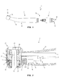
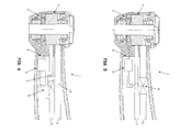
- FIGS. 2 - 8 show sectional views of different embodiments of medical, especially dental, fluid-operated handles with a control or regulating circuit for limiting, controlling or regulating the speed to a maximum or predetermined speed value, which has an actuating element which is supplied by an electrodynamic converter with electrical energy.
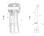
- FIG. 9 shows a medical, especially dental, treatment device with a control and / or regulating device for controlling and / or regulating the rotational speed of the rotary part.
- FIG. 10 and 11 show sectional views through medical, in particular dental, fluid-operated handles for use with a medical, in particular dental, treatment device of FIG. 9 ,
- the Indian FIG. 1 illustrated medical, in particular dental, fluid-operated handle 1 is formed as an elongated tubular instrument having at one end a connection 18 to one or more media sources, for example to a fluid source, in particular to a compressed air source.
- the handle 1 is in accordance FIG. 1 of two parts, namely a handpiece 2 and connectable to the handpiece 2 connecting part 3, which is designed for example as a coupling or adapter.
- the connecting part 3 and the handpiece 2 are detachably connectable to one another by means of a coupling device 19.
- FIG. 1 illustrated medical, in particular dental, fluid-operated handle 1 is formed as an elongated tubular instrument having at one end a connection 18 to one or more media sources, for example to a fluid source, in particular to a compressed air source.
- the handle 1 is in accordance FIG. 1 of two parts, namely a handpiece 2 and connectable to the handpiece 2 connecting part 3, which is designed for example as a coupling or adapter.
- connection 18 comprises a plurality of connecting pieces 20 which connects in the connection part 3 provided lines or channels with one or more media sources, in particular with a compressed air source, preferably with a liquid source.
- the lines or channels pass through the connecting part 3 and pass, preferably via the coupling device 19, the or the media to the handpiece 2.
- the handle 1 has only the handpiece 2 and that at the supply end of the handpiece. 2 a connection 18 similar or identical to one or more media sources is provided.
- a control or control circuit 8 for limiting, controlling or regulating the rotational speed of a rotary part 4 to a speed value which is described in detail below is, preferably completely, received in the handle 1.
- the control or regulating circuit 8 is either completely received in the handpiece 2 or at least parts of the control or regulating circuit 8, in particular an adjusting element 10, preferably a valve 10A, are located in the connecting part 3.
- the handpiece 2 comprises a curved or two angled portions having handle portion 21 and an adjoining headboard 2.
- a tool opening 23 (see FIG. 2 ), through which a tool is releasably inserted into the head part 22.
- the tool opening 23 is arranged laterally on the head part 22, so that the tool protrudes at an angle to the grip part 21 or its longitudinal axis from the head part 22.
- a push-button 24 is provided, which cooperates with a arranged in the head part 22 tool release device to release the tool from the head part 22.
- the handle 1 or the handpiece 2 may also have other known forms, for example, pistol-shaped or straight.
- a fluid line 5 for guiding the drive fluid in the direction of the head part 22 or to a arranged in the head part 22 rotating part 4 and a fluid line 6 for guiding the drive fluid from the head part 22nd away or from the disposed in the head part 22 rotating part 4 away.
- further media lines for example one or more media lines for cooling media, optical fibers or electrical lines extend through the handpiece 2.
- the fluid line 5 conveys the drive fluid, for example compressed air or water, to a drive unit 25 which has at least one rotatable rotary part 4 includes, for example, an impeller, a rotor of an air or vane motor, a shaft, a clamping device for the tool, etc.
- the rotary member 4 comprises an impeller 26 and a hollow shaft 27, to which the impeller 26 is fixed and in which a clamping device for the tool is arranged or which is part of the clamping device.
- the rotary member 4 and the tool connectable thereto are rotatably supported in the handpiece 2 by two roller bearings 28, 29.
- the rolling bearings 28, 29 are on non-rotatable components of the handpiece 2, for example, the outer sleeve 30 (see FIG. 1 ) stored.
- an electrodynamic converter or generator 9 which comprises a rotor and a stator.
- the stator is replaced by at least one, preferably a plurality of coils 11 and preferably a soft magnetic coil core around which the coils 11 are wound formed.
- the coils 11 and the coil core surround the magnetic element 12 having a rotor or are arranged close to the rotor.
- the rotor comprises according to FIG. 2 a magnetic element 12 connected to the rotary part 4 and rotatable with the rotary part 4, in particular a disk-shaped magnetic element having a bore through which the hollow shaft 27 protrudes.
- the impeller 26 is at least partially magnetic, in particular, the blades of the impeller 26 are magnetic.
- the fluid conduit 5 terminates near the rotary member 4 or the impeller 26 or outputs the drive fluid to the rotary member 4, in particular the impeller 26, or into a cavity of the head portion 22 in which the rotary member 4 or the impeller 26 are received.
- the impeller 26 By impinging the impeller 26 with the drive fluid from the fluid conduit 5, the impeller 26 is rotated and thus also the electrodynamic transducer 9 is activated and induced in the coils 11, a voltage.
- the height of the voltage induced in the coils 11 correlates with the rotational speed of the rotor, the rotary part 4 and the tool.
- the generator 9 is part of the control or regulating circuit 8 for limiting, controlling or regulating the rotational speed of the rotary part 4 and / or a tool connected to the rotary part 4.
- the control or regulating circuit 8 comprises in addition to the generator 9 an operable by means of electrical actuator 10, a switching and / or control device 14 and electrical lines 31, 31A which the generator 9 with the switching and / or control device 14 and Connect actuator 10.
- the actuating element 10 designed as a valve, in particular as a control valve or proportional valve, acts on the fluid flowing in the fluid line 5 by means of a positioning process.
- the adjusting element 10 changes the fluid pressure or the volume flow of the drive fluid, in particular by changing the inner diameter of the fluid line 5 which can be flowed through for the drive fluid, as a result of which the rotational speed of the rotary part 4 can be changed.
- the adjusting element 10 receives the electrical energy generated by the generator 9 via the electrical lines 31, 31A. A part of the energy supplied to the rotating part 4 by means of the drive fluid is thus used to operate the adjusting element 10. If the rotational speed of the rotary part 4 is too high, this reduces Actuator 10, the power supplied to the rotary member 4, for example, by reducing the fluid pressure or the volume flow of the drive fluid, whereby the rotational speed of the rotary member 4 decreases. If the rotational speed of the rotary member 4 is too low, the actuator 10 increases the energy supplied to the rotary member 4, for example, by increasing the fluid pressure or the volume flow of the driving fluid, whereby the rotational speed of the rotary member 4 increases.
- the control or regulating circuit 8 consists of the generator 9 driven by the rotary part 4, the adjusting element 10, the electrical lines 31, 31A for connecting the generator 9 to the adjusting element 10 and a part of the fluid line 5.
- the control or regulating circuit 8 additionally contains a switching and / or control device 14, which selectively supplies the actuating element 10 with electrical energy generated by the generator 9, in particular as a function of the rotational speed of the rotary part 4 and which in particular a device 32 for Determining the rotational speed of the rotary member 4, as in FIG. 2 is shown.
- switching and / or control device 14 is formed as a microcomputer or microcontroller 15 and electrically connected between the generator 9 and the actuator 10.
- the microcontroller 15 receives via the lines 31A, the electrical energy generated by the generator 9 and measures or determines a current parameter or value of the electrical energy, which correlates with the rotational speed of the rotary member 4, for example, the voltage or the current.
- the microcontroller 15 or at least parts of the microcontroller 15 thus determine the rotational speed of the rotary part 4 and form the device 32 for determining the rotational speed of the rotary part 4.
- the microcontroller 15 is further stored at least one limit value for the current parameter of the electrical energy, so that the Microcontroller 15 can compare the current parameter with the limit and depending on the ratio of the current parameter to the limit value, the actuator 10 is selectively supplied with electrical energy generated by the generator 9.
- the switching and / or control device 14 supplies the actuator 10 with electrical energy or closes the circuit between the generator 9 and the actuator 10 when the rotational speed of the rotary member 4 and thus the current parameter of the electrical energy generated by the generator 9 the limit reached or exceeded.
- the switching and / or control device 14 interrupts the supply of the actuating element 10 with electrical energy or opens the circuit between the generator 9 and the actuator 10 when the rotational speed of the rotary member 4 and thus the current parameter of the generator 9 generated electrical energy limit reached or fallen below.
- the actuating element 10 which can be operated by means of electrical energy is designed as a proportional valve, wherein the switching and / or control device 14 supplies the proportional valve with electrical energy in such a way that it carries out a continuous adjusting process as a function of the rotational speed of the rotary part 4.
- FIGS. 3 to 8 shown further embodiments of handpieces with a control or regulating circuit 8 for limiting, controlling or regulating the rotational speed of the rotating part similar in many respects to the structure and function of the handpiece 2 of FIG. 2 , For this reason, those features which describe the handpieces of the FIGS. 3 to 8 from the handpiece 2 of FIG. 2 differ.
- the control or regulating circuit 8 of the handpiece 2 of FIG. 3 differs by an alternative embodiment of the switching and / or control device 14 and / or by an alternative embodiment of the device 32 for determining the rotational speed of the rotary part 4:
- the device 32 consists of a radiation source 16, for example one or more light-emitting diodes, and a Radiation-receiving sensor 17, for example, a photodiode.
- the radiation source 16 can be supplied with electrical energy from the electrodynamic converter 9 via the electrical leads 33. If the electrical energy generated by the generator 9 reaches or exceeds a predetermined value, for example the switching voltage or forward voltage of the light-emitting diode, then the radiation source 16 emits electromagnetic radiation.
- the radiation-receiving sensor 17 is arranged and configured to receive this radiation emitted by the radiation source 16.
- the radiation-receiving sensor 17 and / or the switching and / or control device 14 close the circuit between the generator 9 and the actuator 10 , so that the adjusting element 10 can be supplied with the electrical energy generated by the generator 9.
- the radiation-receiving semiconductor element 17 and / or the switching and / or control device 14 opens the circuit between the generator 9 and the control element 10, so that the actuator 10 is no longer supplied with the electrical energy generated by the generator 9.
- the switching and / or control device 14 in turn has a microcontroller 15, which processes the signals of the sensor 17 and causes the closing of the circuit.
- the adjusting element 10, the sensor 17 and / or the switching and / or control device 14 are supplied via the electrical leads 31A with electrical energy generated by the generator 9.
- the devices 32 of the Figures 2 and 3 thus each use (directly or indirectly) the electrical energy generated by the generator 9 or a value thereof for determining the speed.
- a device 32 'for determining the rotational speed of the rotary member 4 is shown, which does not derive the rotational speed of the rotary member 4 from the electrical energy generated by the electrodynamic transducer 9.
- the device 32 ' comprises a sensor for detecting pressure fluctuations in the drive fluid, for example a microphone 34, which detects the sound emitted by the rotary part 4 and changes as a function of the rotational speed or changes in the flow velocity of the drive fluid in the fluid lines 5 or 6.
- the switching and / or control device 14 which in turn preferably has a microcontroller 15, processes the signals of the device 32 ', ie the microphone 34, and closes and opens or closes and opens the circuit between the generator 9 and the actuator 10 as a function of the rotational speed of the rotary part 4 / the signals of the device 32 '.
- the electrical energy generated by the generator 9 thus serves according to this embodiment, the electrical supply of the actuating element 10, the switching and / or control device 14 and the device 32 '(via the electrical lines 33), but not the determination of the rotational speed of the rotary part. 4
- the device 32 'for determining the rotational speed of the rotary part 4, which does not derive the rotational speed of the rotary part 4 from the electrical energy generated by the electrodynamic transducer 9, may alternatively also be formed by other components, for example by an optical detection device which comprises one of the reflected part 4, reflected or guided by the rotary part 4 detected radiation detected.
- Handpiece 2 shown comprises a fluid line 5 for guiding the drive fluid to the rotary member 4 and a secondary line 5A of the fluid line 5, which bypasses the provided in the fluid line 5 actuator 10.
- the secondary line 5A rises with respect to the flow direction of the drive fluid in front of the actuator 10 from the fluid line 5 and flows after the actuator 10 back into the fluid line 5.
- the actuator 10 which in turn is preferably designed as a valve disposed in the fluid line 6 for guiding the drive fluid from the rotary member 4 or head portion 22 away.
- the in the FIGS. 6 and 7 shown handpieces 2 each have a fluid branch line 7, which connects the fluid line 5 for guiding the drive fluid to the rotary member 4 and the fluid line 6 for guiding the drive fluid from the rotary member 4 or short.
- the adjusting element 10, which is preferably designed as a valve, is provided in or on the fluid branch line 7. If the actuating element 10 is not completely closed, then a part of the drive fluid flows directly from the fluid line 5 into the fluid line 6.
- the fluid branch line 7 opens into a pipe section 6A of the fluid line 6 or is connected to the same.
- the fluid line 6 for guiding the drive fluid from the rotary part 4 comprises only a short tube-like section 6B and is subsequently formed by the outer sleeve 30 of the handpiece 2.
- the used or flowing away from the rotary part 4 drive fluid thus flows through the cavity 13 in the outer sleeve 30.
- the fluid branch line 7 also opens in this embodiment in the cavity 13th
- the electrodynamic converter 9 supplies all the components of the control or regulating circuit 8 with electrical energy, in particular the control element 10, the switching and / or control device 14 and the device 32 for determining the rotational speed of the rotary part 4.
- the control or control circuit. 8 or the handle 1 thus require no electrical contacts or lines, which connects the handle 1 with an external, ie located outside of the handle 1, electrical energy source.
- FIGS. 9-11 illustrated treatment device 40 and handles 1 'constructed such that at least according to certain embodiments whose control or control circuit is at least partially operable with electrical energy, which is not formed by a generator 9 electrical energy source comes, in particular from an electrical energy source outside the handle 1 '.
- the treatment device 40 and handles 1 'of FIGS. 9-11 thus, they also have their own inventive aspect independent of the above-described operations.
- the medical, in particular dental, treatment device 40 comprises a handle 1 ', a rotatable part 4 provided in the handle 1' and rotatable by a drive fluid for driving a tool connectable to the rotary part 4, a device 42, 42A for determining the rotational speed of the rotary part 4 and a control and / or regulating device 41 for controlling and / or regulating the rotational speed of the rotary part 4, which is designed to compare the rotational speed of the rotary part 4 determined by the device 42 for determining the rotational speed with a default value and if the determined value deviates Speed of the default value to operate an actuator 10 which acts on the drive fluid to limit the rotational speed of the rotary member 4 to the default value or approximate the default value, wherein the actuator 10 is formed as an operable with electrical power actuator 10 which in the handle 1 'is arranged.
- the great advantage of the arrangement of the actuating element 10 in the handle 1 ' is that the distance between the actuator 10 and the rotary member 4 is very low, whereby the dead time, ie the time between the change of the speed and the reaction of the actuating element, is also very low.
- the entire control or regulating circuit which in particular the device 42, 42A for determining the rotational speed of the rotary member 4, the control and / or regulating device 41 and the actuating element 10, operable with electrical energy and with electrical signals, whereby the operation of the control or regulating circuit is accelerated or the dead time decreases even further.
- the adjusting element 10 is designed as a valve, in particular as a control valve, solenoid valve or proportional valve, or as a throttle.
- the in the FIG. 9 illustrated medical, in particular dental, treatment device 40 comprises a handle 1 ', which is constructed substantially the same as that in FIG. 1
- the handle 1 ' comprises either only a handpiece 2', which releasably via a coupling device 47 at least with a Fluid source 46 and optionally also at least connected to parts of the control and / or regulating device 41, as shown in the FIG. 9 is shown, or alternatively, a handpiece 2 'and a detachable connector part 3, as shown in the FIG. 1 can be seen.
- the medical, in particular dental, treatment device 40 further comprises a power source which provides electrical energy for operating the actuator 10, the energy source being provided either in the handle 1 'or outside the handle 1'.
- the energy source is arranged in the handle 1 ', it comprises, for example, a battery or a rechargeable accumulator or an electrodynamic transducer 9 which can be driven by the drive fluid.
- the electrodynamic transducer 9 or generator can preferably be driven directly or indirectly by the rotary part 4, as it is in FIG. 10 is shown.
- the generator 9 of the handle 1 'of FIG. 10 not only serves or not primarily the power supply of the actuating element 10, but is above all (due to the previously described correlation between the rotational speed of the rotary member 4 and the electrical energy generated by the generator 9) part of the device 42 for determining the speed of Rotary part 4.
- the electrical energy generated by the electrodynamic converter 9 is used exclusively to determine the rotational speed of the rotary part 4.
- the device 42 for determining the rotational speed of the rotary member 4 thus has a drivable by the rotary member 4 electrodynamic transducer 9, so that the rotational speed of the rotary part 4 can be derived from the electrical energy generated by the electrodynamic transducer 9.
- the device 42 is connected via electrical lines 48 to the control and / or regulating device 41 and either directly sends the electrical energy generated by the generator 9 to the control and / or regulating device 41 or modified by means of a component 42 A, the electrical generated by the generator 9 Energy.
- the component 42A is designed, for example, as an amplifier, rectifier, filter, analog-to-digital converter or microcontroller.
- the electrical energy modified by the component 42A is then conducted, in particular in the form of an electrical speed signal, via the electrical lines 48 to the control and / or regulating device 41.
- the control and / or regulating device 41 compares the electrical energy obtained from the device 42 or the speed signal with a fixed or by the User variable speed default value and operates at deviation of the determined speed of the default value by means of a, in particular electrical, control or regulating signal, the actuator 10 such that it acts on the drive fluid to approximate the speed of the rotary member 4 to the speed default value or on it limit as already described above.
- the treatment device 40 comprises a separate electrical energy source via (not shown electrical lines) the actuator 10 and optionally also the device 42 for determining the speed of Rotary part 4, in particular the component 42A, supplied with electrical energy.
- this electrical energy source is arranged outside the handle 1 ', in particular it is formed as part of the control and / or regulating device 41, wherein optionally the electrical lines 48 are also usable for transmitting the electrical energy.
- a releasable electrical connection between the actuator 10 and the electrical energy source is provided, in particular as part of the coupling device 47, for example, electrical sliding contacts or electrical plug contacts.
- control and / or regulating device 41 for controlling and / or regulating the rotational speed of the rotary part 4 completely in the handle 1 ', for example in the component 42A or as part of the component 42A.
- the generator 9 or the electrical energy generated by generator 9 again serves exclusively to determine the rotational speed of the rotary part 4, so that in this case the electrical lines 48 in particular the supply of the control and / or regulating device 41, the device 42 for determining Speed of the rotary member 4 and the actuating element 10 serve with electrical energy.
- the electrical energy is provided by an energy source outside the handle 1 '.
- the device 42 for determining the rotational speed of the rotary part 4 comprises a sensor for detecting pressure fluctuations in the drive fluid, in particular a microphone 34, the sound emitted by the rotary member 4 and varying depending on the speed of sound or changes in the flow velocity of the drive fluid detected.
- the structure of the device 42 corresponds to that in the FIG. 8 described construction of the device 32nd
- the device 42 for determining the rotational speed of the rotary part 4 is formed by an optical detection device 45 which, for example, detects a radiation emitted by the rotary part 4 or reflected by the rotary part 4 (see FIG FIG. 11 ).
- the device 42 comprises, for example, a radiation source 49, in particular a light-emitting diode, which emits radiation in the direction of the rotary part 4.
- a reflector 50 is provided on the rotary part, for example a reflective metal strip which reflects at least part of the radiation to a radiation sensor 51, for example an optical semiconductor, in particular a photodiode.
- the senor By the reflected radiation from the reflector 50 and detected by the sensor 51, the sensor is excited to emit a sensor signal which corresponds to the rotational speed.
- the component 42A which modifies the sensor signal.
- the sensor signal is forwarded to the control and / or regulating device 41, which determines the rotational speed on the basis of the sensor signal, compares with a rotational speed default value and if the determined rotational speed deviates from the default value by means of a, in particular electrical, control or regulating signal, the actuating element 10 operates.
- control and / or regulating device 41 for controlling and / or regulating the rotational speed of the rotary part 4 is provided at least partially outside the handle 1 '.
- the adjusting element 10 is arranged in or on the fluid line 5 for guiding the drive fluid from the fluid source 46 to the rotary part 4.
- the invention is not limited to the illustrated embodiments, but includes all embodiments that apply or include the basic, analogous operating principle of the invention. Furthermore, all features of all described and illustrated embodiments can be combined.
Landscapes
- Health & Medical Sciences (AREA)
- Engineering & Computer Science (AREA)
- General Health & Medical Sciences (AREA)
- Public Health (AREA)
- Dentistry (AREA)
- Epidemiology (AREA)
- Life Sciences & Earth Sciences (AREA)
- Animal Behavior & Ethology (AREA)
- Veterinary Medicine (AREA)
- Oral & Maxillofacial Surgery (AREA)
- Water Supply & Treatment (AREA)
- Physics & Mathematics (AREA)
- Fluid Mechanics (AREA)
- Mechanical Engineering (AREA)
- General Engineering & Computer Science (AREA)
- Dental Tools And Instruments Or Auxiliary Dental Instruments (AREA)
Priority Applications (5)
| Application Number | Priority Date | Filing Date | Title |
|---|---|---|---|
| EP10190072A EP2449999A1 (fr) | 2010-11-05 | 2010-11-05 | Poignée hydraulique médicale, en particulier dentaire |
| US13/283,480 US8936104B2 (en) | 2010-11-05 | 2011-10-27 | Fluid-driven medical or dental handle |
| JP2011238735A JP5314746B2 (ja) | 2010-11-05 | 2011-10-31 | 流体駆動の医療用、特に歯科医療用のハンドグリップ |
| JP2013122115A JP5882949B2 (ja) | 2010-11-05 | 2013-06-10 | 流体駆動の医療用、特に歯科医療用のハンドグリップ |
| US14/564,536 US9784289B2 (en) | 2010-11-05 | 2014-12-09 | Fluid-driven medical or dental handle |
Applications Claiming Priority (1)
| Application Number | Priority Date | Filing Date | Title |
|---|---|---|---|
| EP10190072A EP2449999A1 (fr) | 2010-11-05 | 2010-11-05 | Poignée hydraulique médicale, en particulier dentaire |
Publications (1)
| Publication Number | Publication Date |
|---|---|
| EP2449999A1 true EP2449999A1 (fr) | 2012-05-09 |
Family
ID=44357929
Family Applications (1)
| Application Number | Title | Priority Date | Filing Date |
|---|---|---|---|
| EP10190072A Withdrawn EP2449999A1 (fr) | 2010-11-05 | 2010-11-05 | Poignée hydraulique médicale, en particulier dentaire |
Country Status (3)
| Country | Link |
|---|---|
| US (2) | US8936104B2 (fr) |
| EP (1) | EP2449999A1 (fr) |
| JP (2) | JP5314746B2 (fr) |
Cited By (5)
| Publication number | Priority date | Publication date | Assignee | Title |
|---|---|---|---|---|
| WO2015036840A3 (fr) * | 2013-09-13 | 2015-07-30 | Colibri Spindles Ltd. | Broche entraînée par fluide |
| WO2018234289A1 (fr) | 2017-06-22 | 2018-12-27 | Otto Suhner Ag | Outil pneumatique |
| CH713910A1 (de) * | 2017-06-22 | 2018-12-28 | Suhner Otto Ag | Druckluftgetriebenes Werkzeug. |
| EP3069680B1 (fr) * | 2012-10-25 | 2019-04-03 | W & H Dentalwerk Bürmoos GmbH | Procédé de contrôle d'un instrument médical a entrainement à gaz sous pression et dispositif d'entrainement correspondant |
| EP4011318A1 (fr) * | 2020-12-08 | 2022-06-15 | ReDentNOVA GmbH & Co. KG | Dispositif de commande et de fonctionnement endodontique |
Families Citing this family (11)
| Publication number | Priority date | Publication date | Assignee | Title |
|---|---|---|---|---|
| EP2449999A1 (fr) * | 2010-11-05 | 2012-05-09 | W & H Dentalwerk Bürmoos GmbH | Poignée hydraulique médicale, en particulier dentaire |
| US20150219257A1 (en) * | 2012-08-14 | 2015-08-06 | Stanley Black & Decker, Inc. | Identification device attachments for pneumatic devices |
| EP2727552B1 (fr) * | 2012-11-05 | 2014-10-08 | W & H Dentalwerk Bürmoos GmbH | Pièce à main médicale, en particulier dentaire |
| EP2774571B1 (fr) * | 2013-03-07 | 2018-07-11 | W & H Dentalwerk Bürmoos GmbH | Convertisseur dynamoélectrique et dispositif médical, en particulier dentaire, doté d'un convertisseur dynamoélectrique |
| SE538017C2 (sv) * | 2013-11-01 | 2016-02-09 | Tools Pc Ab Const | Anordning för att mata minst en del av en borrmaskin, borrsystem och metod för matning av minst en del av en borrmaskin |
| US9610137B1 (en) * | 2014-12-02 | 2017-04-04 | Promident LLC | Dental work site illumination system |
| US10207379B2 (en) | 2016-01-21 | 2019-02-19 | Colibri Spindles Ltd. | Live tool collar having wireless sensor |
| EP3698925B1 (fr) * | 2019-02-22 | 2021-10-06 | Max Co., Ltd. | Outil pneumatique |
| US12539201B2 (en) * | 2020-04-27 | 2026-02-03 | Innovative Bioceramix Inc. | Endodontic handpiece systems and methods |
| CN117500634A (zh) * | 2021-07-01 | 2024-02-02 | Dmg森精机株式会社 | 机床、控制方法以及控制程序 |
| JP7557900B1 (ja) | 2023-07-26 | 2024-09-30 | 株式会社ヨシダ技術研究所 | 歯科用ハンドピース制御システム |
Citations (4)
| Publication number | Priority date | Publication date | Assignee | Title |
|---|---|---|---|---|
| DE3246111A1 (de) * | 1981-12-15 | 1983-08-25 | Kabushiki Kaisha Morita Seisakusho, Kyoto | Beruehrungsfreie drehzahlmess-,-anzeige und -regelvorrichtung fuer zahnaerztliche handstuecke |
| JPH05212060A (ja) * | 1992-02-03 | 1993-08-24 | Morita Mfg Co Ltd | 歯科用エアタービン型ハンドピースの回転数制御装置 |
| US20080145817A1 (en) * | 2006-12-18 | 2008-06-19 | Dentsply International Inc. | Closed loop speed control for a pneumatic dental handpiece |
| US20100055642A1 (en) | 2008-08-26 | 2010-03-04 | W&H Dentalwerk Bürmoos GmbH | Fluid-operated medical or dental handle |
Family Cites Families (13)
| Publication number | Priority date | Publication date | Assignee | Title |
|---|---|---|---|---|
| US3019238A (en) * | 1958-08-25 | 1962-01-30 | Upjohn Co | Process for oxidation of 11-hydroxysteroids to 11-ketosteroids |
| US3959883A (en) * | 1973-07-23 | 1976-06-01 | Walls Earl L | Hand control system for power hand tools |
| US4276024A (en) * | 1977-03-28 | 1981-06-30 | Cavitron Corporation | Control systems for dental handpieces |
| JPS58103448A (ja) | 1981-12-15 | 1983-06-20 | 株式会社モリタ製作所 | 歯科用ハンドピ−スの回転数制御方式 |
| JPS6157911U (fr) * | 1984-09-18 | 1986-04-18 | ||
| US4744752A (en) * | 1984-07-30 | 1988-05-17 | Kabushiki Kaisha Morita Seisakusho | Dental handpiece control device |
| JPH069575B2 (ja) * | 1986-01-25 | 1994-02-09 | 株式会社モリタ東京製作所 | 歯科用エアタ−ビンハンドピ−スの回転数制御装置 |
| DE4141673A1 (de) * | 1991-12-17 | 1993-07-01 | Siemens Ag | Regelbare dentalturbine |
| US5507642A (en) * | 1993-06-21 | 1996-04-16 | Siemens Aktiengesellschaft | Dental turbine drive |
| JPH10290810A (ja) | 1997-04-21 | 1998-11-04 | Osada Res Inst Ltd | 歯科治療用ハンドピース |
| JPH1133037A (ja) | 1997-07-22 | 1999-02-09 | Osada Res Inst Ltd | コードレス歯科用エアータービン |
| EP2308408B1 (fr) * | 2007-04-20 | 2014-08-06 | W & H Dentalwerk Bürmoos GmbH | Elément de poignée médical, en particulier dentaire, actionné hydrauliquement |
| EP2449999A1 (fr) * | 2010-11-05 | 2012-05-09 | W & H Dentalwerk Bürmoos GmbH | Poignée hydraulique médicale, en particulier dentaire |
-
2010
- 2010-11-05 EP EP10190072A patent/EP2449999A1/fr not_active Withdrawn
-
2011
- 2011-10-27 US US13/283,480 patent/US8936104B2/en not_active Expired - Fee Related
- 2011-10-31 JP JP2011238735A patent/JP5314746B2/ja not_active Expired - Fee Related
-
2013
- 2013-06-10 JP JP2013122115A patent/JP5882949B2/ja not_active Expired - Fee Related
-
2014
- 2014-12-09 US US14/564,536 patent/US9784289B2/en not_active Expired - Fee Related
Patent Citations (4)
| Publication number | Priority date | Publication date | Assignee | Title |
|---|---|---|---|---|
| DE3246111A1 (de) * | 1981-12-15 | 1983-08-25 | Kabushiki Kaisha Morita Seisakusho, Kyoto | Beruehrungsfreie drehzahlmess-,-anzeige und -regelvorrichtung fuer zahnaerztliche handstuecke |
| JPH05212060A (ja) * | 1992-02-03 | 1993-08-24 | Morita Mfg Co Ltd | 歯科用エアタービン型ハンドピースの回転数制御装置 |
| US20080145817A1 (en) * | 2006-12-18 | 2008-06-19 | Dentsply International Inc. | Closed loop speed control for a pneumatic dental handpiece |
| US20100055642A1 (en) | 2008-08-26 | 2010-03-04 | W&H Dentalwerk Bürmoos GmbH | Fluid-operated medical or dental handle |
Cited By (8)
| Publication number | Priority date | Publication date | Assignee | Title |
|---|---|---|---|---|
| EP3069680B1 (fr) * | 2012-10-25 | 2019-04-03 | W & H Dentalwerk Bürmoos GmbH | Procédé de contrôle d'un instrument médical a entrainement à gaz sous pression et dispositif d'entrainement correspondant |
| WO2015036840A3 (fr) * | 2013-09-13 | 2015-07-30 | Colibri Spindles Ltd. | Broche entraînée par fluide |
| WO2018234289A1 (fr) | 2017-06-22 | 2018-12-27 | Otto Suhner Ag | Outil pneumatique |
| CH713910A1 (de) * | 2017-06-22 | 2018-12-28 | Suhner Otto Ag | Druckluftgetriebenes Werkzeug. |
| US11607788B2 (en) | 2017-06-22 | 2023-03-21 | Suhner Schweiz Ag | Compressed air-driven tool |
| EP4011318A1 (fr) * | 2020-12-08 | 2022-06-15 | ReDentNOVA GmbH & Co. KG | Dispositif de commande et de fonctionnement endodontique |
| WO2022122602A1 (fr) | 2020-12-08 | 2022-06-16 | Redent Nova Gmbh & Co. Kg | Dispositif d'entraînement et d'actionnement endodontique |
| CN117042718A (zh) * | 2020-12-08 | 2023-11-10 | 瑞丹特诺瓦有限责任两合公司 | 牙髓驱动和操作装置 |
Also Published As
| Publication number | Publication date |
|---|---|
| JP5314746B2 (ja) | 2013-10-16 |
| JP5882949B2 (ja) | 2016-03-09 |
| US9784289B2 (en) | 2017-10-10 |
| JP2013208482A (ja) | 2013-10-10 |
| US8936104B2 (en) | 2015-01-20 |
| US20120111590A1 (en) | 2012-05-10 |
| JP2012101055A (ja) | 2012-05-31 |
| US20150090472A1 (en) | 2015-04-02 |
Similar Documents
| Publication | Publication Date | Title |
|---|---|---|
| EP2727552B1 (fr) | Pièce à main médicale, en particulier dentaire | |
| EP2308408B1 (fr) | Elément de poignée médical, en particulier dentaire, actionné hydrauliquement | |
| EP2671531B1 (fr) | Outil de forage médical, notamment dentaire | |
| JP7253652B2 (ja) | 単一挿入複数サンプリング生検装置 | |
| US9784289B2 (en) | Fluid-driven medical or dental handle | |
| DE102009049924A1 (de) | Druckwellengerät mit pneumatischem Antrieb | |
| EP2158870B1 (fr) | Poignée hydraulique médicale, en particulier dentaire | |
| DE3034292A1 (de) | Manipulator | |
| DE3526877C2 (fr) | ||
| EP0361332A1 (fr) | Petite turbine hydraulique, en particulier pour installations sanitaires domestiques | |
| DE2949172A1 (de) | Drehzahlgeregelter elektromotor | |
| EP1949869A1 (fr) | Pièce à main médicale, en particulier dentaire, entrainée mécaniquement | |
| DE102009038551A1 (de) | Greifvorrichtung | |
| EP2073349B1 (fr) | Moteur électrique avec conduites de fluide traversant le stator | |
| DE2207240A1 (de) | Absperr- und einstellventil fuer zahnaerztliche handstuecke | |
| EP2704295B1 (fr) | Dispositif médical, en particulier dentaire, avec un convertisseur électromécanique | |
| DE1791047C3 (de) | Bohrgerät, insbesondere zahnärztliches Handgerät | |
| EP2774571A1 (fr) | Convertisseur dynamoélectrique et dispositif médical, en particulier dentaire, doté d'un convertisseur dynamoélectrique | |
| WO2021190852A1 (fr) | Procédé de commande d'un dispositif d'extraction de racine dentaire en particulier et dispositif | |
| EP3642456B1 (fr) | Outil pneumatique | |
| EP1982667B1 (fr) | Pièce à main médicale, notamment dentaire, entraînée par un fluide | |
| WO2018234289A1 (fr) | Outil pneumatique | |
| DE102014203328A1 (de) | Handwerkzeugmaschine mit einem Bearbeitungswerkzeug und einem elektromotorischen Antrieb | |
| DE3246111A1 (de) | Beruehrungsfreie drehzahlmess-,-anzeige und -regelvorrichtung fuer zahnaerztliche handstuecke | |
| CN110432971A (zh) | 一种骨科用克氏针推进器 |
Legal Events
| Date | Code | Title | Description |
|---|---|---|---|
| PUAI | Public reference made under article 153(3) epc to a published international application that has entered the european phase |
Free format text: ORIGINAL CODE: 0009012 |
|
| 17P | Request for examination filed |
Effective date: 20111011 |
|
| AK | Designated contracting states |
Kind code of ref document: A1 Designated state(s): AL AT BE BG CH CY CZ DE DK EE ES FI FR GB GR HR HU IE IS IT LI LT LU LV MC MK MT NL NO PL PT RO RS SE SI SK SM TR |
|
| AX | Request for extension of the european patent |
Extension state: BA ME |
|
| STAA | Information on the status of an ep patent application or granted ep patent |
Free format text: STATUS: THE APPLICATION IS DEEMED TO BE WITHDRAWN |
|
| 18D | Application deemed to be withdrawn |
Effective date: 20160601 |