EP0550920A2 - Vorrichtung zum Bearbeiten von Produkten aus Metall - Google Patents
Vorrichtung zum Bearbeiten von Produkten aus Metall Download PDFInfo
- Publication number
- EP0550920A2 EP0550920A2 EP92203540A EP92203540A EP0550920A2 EP 0550920 A2 EP0550920 A2 EP 0550920A2 EP 92203540 A EP92203540 A EP 92203540A EP 92203540 A EP92203540 A EP 92203540A EP 0550920 A2 EP0550920 A2 EP 0550920A2
- Authority
- EP
- European Patent Office
- Prior art keywords
- shear blade
- frame
- main plate
- carrier plate
- plate
- Prior art date
- Legal status (The legal status is an assumption and is not a legal conclusion. Google has not performed a legal analysis and makes no representation as to the accuracy of the status listed.)
- Granted
Links
Images


Classifications
-
- B—PERFORMING OPERATIONS; TRANSPORTING
- B21—MECHANICAL METAL-WORKING WITHOUT ESSENTIALLY REMOVING MATERIAL; PUNCHING METAL
- B21D—WORKING OR PROCESSING OF SHEET METAL OR METAL TUBES, RODS OR PROFILES WITHOUT ESSENTIALLY REMOVING MATERIAL; PUNCHING METAL
- B21D28/00—Shaping by press-cutting; Perforating
- B21D28/02—Punching blanks or articles with or without obtaining scrap; Notching
- B21D28/12—Punching using rotatable carriers
Definitions
- the invention relates to an apparatus for working metal workpieces, comprising a frame, a carrier plate pivotably mounted in the frame and carrying a substantially triangular shear blade, wherein two triangle sides enclose a right angle and provide the cutting edges extending substantially horizontally and vertically, respectively, wherein the shear blade is accommodated in a complementary recess in the carrier plate rotatable around a shear blade axis and wherein the frame supports a stationary counter shear blade.
- German patent 3 038 817 describes an apparatus of this type, wherein the shear blade axis lies at the intersection of the cutting edges and the guiding of the shear blade along the bisector of the right angle is obtained by forming special guide faces on the shear blade and by providing the frame with guide pins. Further, the shear blade is coupled with the carrier plate by an arcuate edge. This known construction is thereby rather complicated. Moreover, the load during operation on the guide faces and the guide pins is relatively high due to the location of the shear blade axis.
- the invention aims in the first place to provide an improvement apparatus of the above-mentioned type.
- the apparatus according to the invention is characterized in that the shear blade axis is made as a pin connecting the shear blade rotatably with the carrier plate and being located at the bisector of the right angle between the cutting edges of the shear blade at a distance from said angle, wherein the frame carries a guide guiding the shear blade along said bisector during pivoting of the carrier plate.
- the load of the guide during operation is relatively low because the cutting forces exerted on the shear blade mainly compensate each other on both sides of the shear blade axis, so that the cutting forces are mainly taken by the cooperation between the arcuate triangle side of the shear blade and the corresponding arcuate side of the recess in the carrier plate. Because the cutting edges extend horizontally and vertically, respectively, the apparatus is very convenient to use.
- the guide comprises a cam cooperating with a slot formed in the shear blade and extending along said bisector.
- the guide is possible to provide the guide with the slot and the shear blade with the cooperating cam.
- the apparatus is of the type having a main plate movable up and down, it is possible according to the invention to couple the carrier plate with the main plate and to drive the carrier plate by the main plate.
- the carrier plate is driven by a hydraulic cylinder piston assembly.
- This embodiment shows the advantage that the tools of the carrier plate can be used independent of the tools of the main plate.
- An apparatus of the above-mentioned type provided with a main plate movable up and down and guided in the frame comprises generally a plurality of tools carried by the main plate.
- these tools generally consist of cutting tools, for example a shear blade for cutting plates or strips and shear blades for cutting round and square workpieces, respectively.
- both main surfaces of the main plate each carry one or more protruding tools.
- Such tools are for example a forming unit, an angle punch or the like.
- the tools provided on both sides of the main plate are fixed by means of common mounting openings in the main plate. Thereby it is obtained that weakened locations are present in the main plate at one location only for mounting two tools.
- the application possibilities of the apparatus are still increased if at least one of the vertical end faces of the main plate carries at least one tool.
- the frame of the apparatus described generally comprises two web plates enclosing the main plate.
- the web plates are interconnected above and below the main plate in an non-slidable manner, for example by cooperating key parts and slots. In this manner it is obtained that the web plates and the main plate may take very high forces.
- the invention further relates to an apparatus for working metal workpieces, comprising a frame with two web plates enclosing an intermediate space and a slide movable up and down and guided in the frame.
- Such an apparatus generally will include also the above described pivotable carrier plate and a main plate movable up and down, each with associated tools.
- the applications of such an apparatus are increased in that the web plates at the location of the slide have a flat mainly vertical end edge and that the slide is adjacent to said end edge with a mainly vertical side, said side carrying a protruding bending tool cooperating with a die tool fixed to the frame.
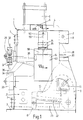
- Fig. 1 is a side view of an embodiment of the apparatus according to the invention.
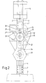
- Fig. 2 is a front view of the apparatus of Fig. 1.
- Fig. 3 is a top view of the apparatus of Fig. 1.
- Fig. 4 shows in a larger scale a detail of the apparatus of Fig. 1.
- Fig. 5 is a section according to the line V-V of Fig. 4.
- Fig. 6 is a section of the stationary tool turret of the apparatus of Fig. 1.
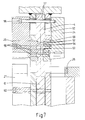
- Fig. 7 is a section according to the line VII-VII in Fig. 1.
- Fig. 8 is a side view of a second embodiment of the apparatus according to the invention.
- Fig. 9 is a back view of the apparatus of Fig. 8.
- Fig. 10 is a side view partially shown of a third embodiment of the apparatus according to the invention.
- Fig. 11 is a partially shown top view of the apparatus of Fig. 10.
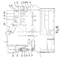
- Fig. 12 is a side view of a fourth embodiment of the apparatus according to the invention.
- the apparatus shown in Fig. 1-3 for working metal workpieces comprises a frame 1 made of two web plates 2 joining a base plate 3.
- a main plate 4 movable up and down is guided between the web plates 2 and is driven by a hydraulic cylinder piston assembly 5 mounted at the top side of the apparatus on the web plates 2.
- the head of a bolt 6 can be seen in Fig. 1, by means of which the main plate 4 is connected with the piston not shown of the cylinder piston assembly 5.
- the main plate 4 is enclosed between fixed guiding blocks 7 at the front side of the apparatus and adjustable guiding blocks 8 at the back side and the lower centre part of the apparatus, respectively. Suitable sliding elements can be provided between the guiding blocks 7, 8 and the main plate 4.
- the apparatus further comprises a carrier plate 9 pivotably borne in the frame 1 and connected to the main plate 4 by a bearing 10.
- the carrier plate 9 is therefore also driven through the main plate 4 by the cylinder piston assembly 5.
- the carrier plate 9 comprises a substantially triangular shear blade 11, the straight triangle sides of which enclose a right angle and form the cutting edges 12 of the shear blade 11 extending substantially horizontally and vertically, respectively.
- the frame 1 supports a stationary shear blade 13 with corresponding cutting edges 14.
- a suitable opening 15 is provided in the web plate 2 shown in Fig. 1 for reaching and, if necessary, changing the shear blade 11, while a substantially L-shaped opening 16 is provided in the other web plate 2, so that angle workpieces and the like can be cut.
- the shear blade 11 further comprises an arcuate triangle side and is mounted in a recess of the carrier plate 9 complementary to the shear blade 11, by means of a bolt 17.
- the bolt 17 determines a shear blade axis lying at a distance from the angle as determined by the cutting edges 12, namely at the bisector of this right angle.
- a guiding element 19 is fixed to the frame 1, said guiding element carrying an elongated cam 20.
- This cam 20 engages a slot 21 of the shear blade 11, said slot extending according to the bisector of the right angle between the cutting edges 12. It is also possible to provide the shear blade 11 with the cam 20 and to provide the slot 21 in the guiding element 19.
- the location of the shear blade axis 17 at a distance of the right angle results in the advantage that the cutting forces occurring during operation at both sides of the shear blade axis 17 partially counter balance each other so that these cutting forces are taken by the engagement of the arcuate triangle side and the arcuate edge of the recess 18 in the carrier plate 9. Thereby the cam 20 is not heavily loaded. Because the main plate 4 engages the carrier plate 9 at the bearing 10, a higher cutting force is available at the location of the shear blade 11 than the force provided by the cylinder piston assembly 5.
- the carrier plate 9 further carries a shear blade 22 and the frame at this location carries a counter shear blade 23 for cutting flat workpieces.
- Fig. 1-3 further show that the main plate 4 is provided with a protruding tool 24, 25 on both main surfaces.
- the tool 24 is made as a triangular punch cooperating with a die 26 supported by a corresponding web plate 2 of the frame 1.
- the tool 25 is made as a forming unit cooperating with a die 27 supported by the corresponding web plate 2 of the frame 1.
- both vertical end faces of the main plate 4 also each carry a tool 28, 29, respectively.
- the tool at the back side is made as a rectangular punch cooperating with a die 30 supported by the frame 1.
- the tool 29 is made as a rotatable tool turret and will be further explained hereinafter.
- the web plates 2 of the frame 1 are coupled with each other in a non-slidable manner above and below the main plate 4.
- one of the web plates 2 is provided with projecting key parts at its upper and lower sides in a manner not further shown, said key parts fittingly engaging slots provided at the upper and lower sides of the other web plate.
- Fig. 1 it is further indicated that the frame 1 and the main plate 4 are also provided with cutting tools 31 for cutting round and square workpieces.
- the tool 29 is made as a rotatable tool turret carrying six different punch tools 32. By rotating the tool turret 29 these punch tools 32 may subsequently be located in a vertically downwardly directed working position.
- a tool turret 33 which is also rotatable, is mounted on the frame 1 in a fixed position and carries die tools 34 corresponding with the different punch tools 32, which die tools may be located in an upwardly directed working position by rotation of the tool turret.
- the frame 1 further carries a detainer which, during the upward movement of the tool turret 29, prevents the workpiece to follow the punch tool 32.
- the detainer 35 is slidable on a guide 36.
- Fig. 6 shows a horizontal section of the fixed or stationary tool turret 33; the construction of the tool turret 29 fully corresponds with the same of the tool turret 33 wherein of course instead of die tools 34 punch tools 32 are provided. The construction of the tool turret 29 will not be described separately.
- the tool turret 33 comprises a carrier plate 37 attached to the web plates 2 and a round support 38 attached to this carrier plate 37, said support being stepped in section.
- a drum 39 is rotatably mounted on this round support 38, said drum 39 carrying the die tools 34 or punch tools 32.
- the drum 39 is locked in the desired position by a locking pin 40 adapted to engage with a bevelled head 41 which is V-shaped in section, in openings 42 of the drum 39 having a V-shape in section. For each die or punch tool a corresponding V-shaped opening 42 is provided.
- the locking pin 40 is carried by an arm 43 received in a chamber 44 formed in the carrier plate 37.
- a shaft 45 is rotatably received in an axial cavity 46 in the support 38 and also extends rotatably the arm 43.
- a hexagonal part 47 projects through a complementary opening in a closing cap 48 of the drum 39.
- each tool turret 29, 33 is provided with a detector 50 for detecting the rotational position of the corresponding tool turret 29, 33.
- this detector 50 comprises a switch with six positions, the shaft 51 of which is coupled with the shaft 45 in a non-rotatable manner. Both detectors 50 are connected with the usual operating means of an apparatus of this type in such a manner that the cylinder piston assembly 5 can only drive the main plate 4 if corresponding punch and die tools are in the working position.
- the tools 24, 25 are aligned opposite each other wherein the mounting of these tools to the main plate 4 is provided by means of common mounting openings in the main plate 4. Thereby it is obtained that for two tools weakened locations in the main plate 4 are required at one location only.
- Fig. 7 shows a cross section of the apparatus described at the location of the tools 24, 25, wherein the mounting of these tools to the main plate 4 is shown in more detail.
- Slots 52 are provided in the main plate 4 whereas slots 53 are provided at the side of the tools 24, 25 directed to the main plate 4, whereby projecting parts 54 are obtained.
- These parts 54 fittingly engage as keys in the slots 52 of the main plate 4 so that shearing forces occurring during operation are taken by this slot and key connection 52, 54.
- the tools 24, 25 are fixed to the main plate 4 by means of a plurality of draw bolts 55 at the location of the key and slot connection 52, 54. At the upper side the tools 24, 25 are fixed by one (or more) draw bolt(s) 56, wherein spacers 57 are provided between the tools 24, 25 and the main plate 4. Of course suitable openings 58 and slots 59 are formed in the web plates 2 to provide the required freedom of movement.
- the supports for the dies 26, 27 are fixed to the web plates 2 by draw bolts 60. Between the die supports 26, 27 and the web plates a key and slot connection or the like can also be provided for taking the shearing forces. Slots 61 are provided in the main plate 4 to receive the draw bolts 60.
- the part of the apparatus with the carrier plate 9 and the shear blade 11 can also be used separately from the other parts of this apparatus. It is also possible to equip the apparatus with the tools 24, 25, 28, 29 without the use of the pivotable carrier plate 9. Further, it is possible to equip an apparatus with the tool turrets 29, 33 only, wherein the tool turret 29 is directly driven by a cylinder piston assembly.
- FIG. 8 An apparatus made in this manner is schematically shown in a side view in Fig. 8.
- the web plates 2 at the front side of the apparatus carry a guide track 100, a slide 101 being movable up and down along said track.
- the slide 101 is driven by a hydraulic cylinder piston assembly 102.
- the centre line of the cylinder piston assembly 102 coincides with the centre line of the punch tool 32 lying in the working position, whereby a very favourable force transmission is obtained.
- the slide 101 is U-shaped and carries the tool turret 29 which is borne at both sides in the U-shaped slide 101 by a schematically indicated shaft 103.
- the tool turret 33 is also borne at both sides in a U-shaped holder 105 by a schematically indicated shaft 104.
- the holder 105 is stationary supported on the frame 1.
- the pivotable carrier plate 9 can be driven by a hydraulic cylinder piston assembly 106 which is located in an oblique position substantially right above the pivot point of the carrier plate 9.
- the connection point between the cylinder piston assembly 106 and the carrier plate 9 lies between two boundary planes which are determined respectively by the centre lines of the pivot point of the carrier plate 9 and the hinge point connecting the cylinder piston assembly with the frame and the vertical end face 113 of the frame.
- the carrier plate 9 is equipped with a triangular shear blade not shown in the manner described.
- the carrier plate 9 also includes the cutting tools 31.
- the carrier plate 9 is also provided with a tool 28 cooperating with a die 30 supported by the frame 1.
- the carrier plate 9 is equipped with the shear blade 22 whereas the frame at this location supports a counter shear blade 23 for cutting flat workpieces.
- each web plate 2 is provided with a slot 109 as shown in a top view according to Fig. 11.
- the clearance for the movement of the slide 108 in the slots 109 is adjustable by means of an adjustment wedge 110.
- the slide 108 carriers a bending tool 111 cooperating with a die 112 supported by the frame 1 and having different V-shaped recesses.
- the web plates 2 at the location of the slide 109 have a flat mainly vertical end edge 113 so that the bending tool 111 and the die 112 are completely freely accessible. Thereby the material to be bent does not meet any obstructions during bending and the most fantastic shapes can be bent.
- Fig. 10 partially shows a side view of another embodiment of the apparatus according to the invention mainly corresponding with the embodiment of Fig. 8.
- the slide 108 is not coupled by a link with the pivotable carrier plate 9.
- the slide 108 is driven by a hydraulic cylinder piston assembly 114.
- This embodiment further fully corresponds with the embodiment of Fig. 8.
- Fig. 11 shows a top view of the apparatus of Fig. 10, wherein the slide 108, the slots 109 and the adjustment wedge 110 can be seen.
- the bending tool 111 is fixed to the slide 108 by means of a bolt 115 and a key 116.
- Fig. 12 shows a side view of an apparatus mainly corresponding with the embodiment of Fig. 8.
- the die tool turret 33 is supported on the frame 1 rotatably around a vertical axis 117.
- both tools 33, 34 located in a working position are located on a centre line intersecting the horizontal axis of the tool turret 29.
Landscapes
- Engineering & Computer Science (AREA)
- Mechanical Engineering (AREA)
- Electrical Discharge Machining, Electrochemical Machining, And Combined Machining (AREA)
- Punching Or Piercing (AREA)
- Control And Other Processes For Unpacking Of Materials (AREA)
- Preventing Corrosion Or Incrustation Of Metals (AREA)
- Mounting, Exchange, And Manufacturing Of Dies (AREA)
- Bending Of Plates, Rods, And Pipes (AREA)
- Shearing Machines (AREA)
- Forging (AREA)
Applications Claiming Priority (4)
| Application Number | Priority Date | Filing Date | Title |
|---|---|---|---|
| NL9101929A NL9101929A (nl) | 1991-11-19 | 1991-11-19 | Inrichting voor het bewerken van metalen werkstukken. |
| NL9101929 | 1991-11-19 | ||
| NL9201637 | 1992-09-22 | ||
| NL9201637A NL9201637A (nl) | 1991-11-19 | 1992-09-22 | Inrichting voor het bewerken van metalen werkstukken. |
Publications (3)
| Publication Number | Publication Date |
|---|---|
| EP0550920A2 true EP0550920A2 (de) | 1993-07-14 |
| EP0550920A3 EP0550920A3 (en) | 1993-10-06 |
| EP0550920B1 EP0550920B1 (de) | 1997-03-05 |
Family
ID=26646899
Family Applications (2)
| Application Number | Title | Priority Date | Filing Date |
|---|---|---|---|
| EP93900461A Expired - Lifetime EP0693009B1 (de) | 1991-11-19 | 1992-11-18 | Vorrichtung zum bearbeiten von metallischen produkten |
| EP92203540A Expired - Lifetime EP0550920B1 (de) | 1991-11-19 | 1992-11-18 | Vorrichtung zum Bearbeiten von Produkten aus Metall |
Family Applications Before (1)
| Application Number | Title | Priority Date | Filing Date |
|---|---|---|---|
| EP93900461A Expired - Lifetime EP0693009B1 (de) | 1991-11-19 | 1992-11-18 | Vorrichtung zum bearbeiten von metallischen produkten |
Country Status (9)
| Country | Link |
|---|---|
| US (1) | US5483814A (de) |
| EP (2) | EP0693009B1 (de) |
| JP (1) | JPH07501015A (de) |
| AT (1) | ATE148842T1 (de) |
| DE (2) | DE69217898T2 (de) |
| DK (1) | DK0693009T3 (de) |
| ES (1) | ES2097488T3 (de) |
| NL (1) | NL9201637A (de) |
| WO (1) | WO1993009891A1 (de) |
Cited By (2)
| Publication number | Priority date | Publication date | Assignee | Title |
|---|---|---|---|---|
| EP1302619A1 (de) * | 2001-10-12 | 2003-04-16 | Teh Yor Industrial Co. Ltd. | Vorrichtung und Verfahren zum Schneiden von Jalousien |
| CN108907157A (zh) * | 2018-07-05 | 2018-11-30 | 苏州广型模具有限公司 | 管体快速切边模具 |
Families Citing this family (3)
| Publication number | Priority date | Publication date | Assignee | Title |
|---|---|---|---|---|
| US6820455B1 (en) | 2001-09-17 | 2004-11-23 | Wesley Allen Bainter | Metal working machine |
| TWI643686B (zh) * | 2017-01-18 | 2018-12-11 | 啟翔股份有限公司 | 自動切換沖頭裝置 |
| CN111545641B (zh) * | 2020-04-26 | 2021-09-21 | 合肥众机群机械制造有限公司 | 一种吊耳加工用冲弯曲装置 |
Family Cites Families (15)
| Publication number | Priority date | Publication date | Assignee | Title |
|---|---|---|---|---|
| DE78271C (de) * | J. P. JOHANSSON, Enköping, Schweden | Revolverpresse | ||
| FR356032A (fr) * | 1905-07-10 | 1905-11-18 | Arthur Vernet | Tourelles pour poinconneuse-revolver simple ou multiple avec ou sans cisaille |
| FR507999A (fr) * | 1919-12-31 | 1920-09-28 | Victor Lucas | Perfectionnement apporté aux machines à poinconner |
| US1675801A (en) * | 1926-09-23 | 1928-07-03 | Thomas A Gorman | Stamping apparatus |
| US2789639A (en) * | 1950-09-09 | 1957-04-23 | Lorentzen Hardware Mfg Corp | Method useful in the manufacture of venetian blinds |
| FR1243492A (fr) * | 1959-09-02 | 1960-10-14 | Ets Grimar | Machine à poinçonner |
| US3701276A (en) * | 1970-07-15 | 1972-10-31 | Excel Mfg Ltd | Iron and metal working machinery |
| US3830129A (en) * | 1973-07-09 | 1974-08-20 | Manco Mfg Co | Machine tool with swingable tool mount |
| US3866522A (en) * | 1973-07-27 | 1975-02-18 | Jr Harry L Oswalt | Metal working machine |
| FR2317058A1 (fr) * | 1975-07-09 | 1977-02-04 | Beauplat Fils Et Cie | Tourelle porte-outils perfectionnee pour machine a poinconner |
| DE2648447A1 (de) * | 1976-10-26 | 1978-04-27 | Peddinghaus Rolf | Werkzeugmaschine mit zwei revolvertrommeln |
| GB1569335A (en) * | 1976-10-30 | 1980-06-11 | Sumitomo Metal Ind | Die forging press |
| ES249858Y (es) * | 1980-04-07 | 1981-05-16 | Dispositivo cortador de perfiles angulares,aplicable a ciza-llas hidraulicas | |
| DE3241844C1 (de) * | 1982-11-12 | 1984-08-16 | Rolf Dipl.-Ing. 5828 Ennepetal Peddinghaus | Stanzmaschine mit Revolvertrommel |
| NZ214551A (en) * | 1984-12-20 | 1987-02-20 | Liras Pty Ltd | Hydraulic press with"floating"hydraulic cylinder |
-
1992
- 1992-09-22 NL NL9201637A patent/NL9201637A/nl not_active Application Discontinuation
- 1992-11-18 US US08/211,815 patent/US5483814A/en not_active Expired - Fee Related
- 1992-11-18 AT AT93900461T patent/ATE148842T1/de not_active IP Right Cessation
- 1992-11-18 EP EP93900461A patent/EP0693009B1/de not_active Expired - Lifetime
- 1992-11-18 DK DK93900461.0T patent/DK0693009T3/da active
- 1992-11-18 DE DE69217898T patent/DE69217898T2/de not_active Expired - Fee Related
- 1992-11-18 ES ES93900461T patent/ES2097488T3/es not_active Expired - Lifetime
- 1992-11-18 DE DE69217507T patent/DE69217507T2/de not_active Expired - Fee Related
- 1992-11-18 WO PCT/NL1992/000207 patent/WO1993009891A1/en not_active Ceased
- 1992-11-18 JP JP5509170A patent/JPH07501015A/ja active Pending
- 1992-11-18 EP EP92203540A patent/EP0550920B1/de not_active Expired - Lifetime
Cited By (2)
| Publication number | Priority date | Publication date | Assignee | Title |
|---|---|---|---|---|
| EP1302619A1 (de) * | 2001-10-12 | 2003-04-16 | Teh Yor Industrial Co. Ltd. | Vorrichtung und Verfahren zum Schneiden von Jalousien |
| CN108907157A (zh) * | 2018-07-05 | 2018-11-30 | 苏州广型模具有限公司 | 管体快速切边模具 |
Also Published As
| Publication number | Publication date |
|---|---|
| DE69217507D1 (de) | 1997-03-27 |
| DE69217898D1 (de) | 1997-04-10 |
| EP0693009A1 (de) | 1996-01-24 |
| ES2097488T3 (es) | 1997-04-01 |
| EP0550920A3 (en) | 1993-10-06 |
| EP0693009B1 (de) | 1997-02-12 |
| US5483814A (en) | 1996-01-16 |
| DK0693009T3 (da) | 1997-07-14 |
| JPH07501015A (ja) | 1995-02-02 |
| NL9201637A (nl) | 1993-06-16 |
| WO1993009891A1 (en) | 1993-05-27 |
| DE69217898T2 (de) | 1997-07-24 |
| EP0550920B1 (de) | 1997-03-05 |
| DE69217507T2 (de) | 1997-06-26 |
| ATE148842T1 (de) | 1997-02-15 |
Similar Documents
| Publication | Publication Date | Title |
|---|---|---|
| US6314851B1 (en) | Dual mini-blind cutter | |
| KR890000852B1 (ko) | 전단기 | |
| US4457197A (en) | Device for cutting and/or stamping metal bars and sections | |
| JP5230743B2 (ja) | スライダ受け手段を備えたくさび駆動装置 | |
| US5799557A (en) | Venetian blind cutting machine | |
| US4901427A (en) | Punch press | |
| EP0550920B1 (de) | Vorrichtung zum Bearbeiten von Produkten aus Metall | |
| KR890004036B1 (ko) | 절곡기의 공구길이 조정장치 | |
| CA1237066A (en) | Shear for different structural shapes | |
| CN117259568B (zh) | 一种不锈钢钣金加工用冲孔装置 | |
| SK279575B6 (sk) | Ohýbací stroj na ohýbanie plechov | |
| US4267758A (en) | Actuator mount for power shear or punch | |
| US4267756A (en) | Holddown for power shear | |
| WO1999002333A1 (en) | Press device for processing lead frames | |
| US5341700A (en) | X-Y movement mechanism | |
| CN212398310U (zh) | 一种剪板机间隙调整机构 | |
| US4638699A (en) | Shear for profile and/or flat and/or solid-section steel stock | |
| JPS62292214A (ja) | 棒鋼圧延機のガイド移動装置 | |
| US4109554A (en) | Feed guide attachment for band saw machines | |
| US4409871A (en) | Shear for bar stock | |
| CN219561625U (zh) | 适用于超宽料加工的锯头 | |
| US4685365A (en) | Profile-bar cutter with angled blade movement | |
| US5542283A (en) | Bending machine | |
| CN112222279A (zh) | 凸轮切料结构及其运作方法 | |
| CN222402903U (zh) | 一种钣金折弯装置 |
Legal Events
| Date | Code | Title | Description |
|---|---|---|---|
| PUAI | Public reference made under article 153(3) epc to a published international application that has entered the european phase |
Free format text: ORIGINAL CODE: 0009012 |
|
| AK | Designated contracting states |
Kind code of ref document: A2 Designated state(s): BE DE ES FR GB NL SE |
|
| PUAL | Search report despatched |
Free format text: ORIGINAL CODE: 0009013 |
|
| AK | Designated contracting states |
Kind code of ref document: A3 Designated state(s): BE DE ES FR GB NL SE |
|
| 17P | Request for examination filed |
Effective date: 19940331 |
|
| 17Q | First examination report despatched |
Effective date: 19951206 |
|
| GRAG | Despatch of communication of intention to grant |
Free format text: ORIGINAL CODE: EPIDOS AGRA |
|
| GRAH | Despatch of communication of intention to grant a patent |
Free format text: ORIGINAL CODE: EPIDOS IGRA |
|
| GRAH | Despatch of communication of intention to grant a patent |
Free format text: ORIGINAL CODE: EPIDOS IGRA |
|
| GRAA | (expected) grant |
Free format text: ORIGINAL CODE: 0009210 |
|
| AK | Designated contracting states |
Kind code of ref document: B1 Designated state(s): BE DE ES FR GB NL SE |
|
| PG25 | Lapsed in a contracting state [announced via postgrant information from national office to epo] |
Ref country code: FR Effective date: 19970305 Ref country code: ES Free format text: THE PATENT HAS BEEN ANNULLED BY A DECISION OF A NATIONAL AUTHORITY Effective date: 19970305 Ref country code: BE Effective date: 19970305 |
|
| REF | Corresponds to: |
Ref document number: 69217898 Country of ref document: DE Date of ref document: 19970410 |
|
| ITF | It: translation for a ep patent filed | ||
| PG25 | Lapsed in a contracting state [announced via postgrant information from national office to epo] |
Ref country code: SE Effective date: 19970605 |
|
| EN | Fr: translation not filed | ||
| PLBE | No opposition filed within time limit |
Free format text: ORIGINAL CODE: 0009261 |
|
| 26N | No opposition filed | ||
| PGFP | Annual fee paid to national office [announced via postgrant information from national office to epo] |
Ref country code: GB Payment date: 19991117 Year of fee payment: 8 |
|
| PGFP | Annual fee paid to national office [announced via postgrant information from national office to epo] |
Ref country code: NL Payment date: 19991130 Year of fee payment: 8 |
|
| PGFP | Annual fee paid to national office [announced via postgrant information from national office to epo] |
Ref country code: DE Payment date: 20000114 Year of fee payment: 8 |
|
| PG25 | Lapsed in a contracting state [announced via postgrant information from national office to epo] |
Ref country code: GB Free format text: LAPSE BECAUSE OF NON-PAYMENT OF DUE FEES Effective date: 20001118 |
|
| PG25 | Lapsed in a contracting state [announced via postgrant information from national office to epo] |
Ref country code: NL Free format text: LAPSE BECAUSE OF NON-PAYMENT OF DUE FEES Effective date: 20010601 |
|
| GBPC | Gb: european patent ceased through non-payment of renewal fee |
Effective date: 20001118 |
|
| NLV4 | Nl: lapsed or anulled due to non-payment of the annual fee |
Effective date: 20010601 |
|
| PG25 | Lapsed in a contracting state [announced via postgrant information from national office to epo] |
Ref country code: DE Free format text: LAPSE BECAUSE OF NON-PAYMENT OF DUE FEES Effective date: 20010801 |