EP0550971A1 - Engrenages de transmission comportant des éléments de freinage et d'embrayage fixés par une surface ondulée - Google Patents
Engrenages de transmission comportant des éléments de freinage et d'embrayage fixés par une surface ondulée Download PDFInfo
- Publication number
- EP0550971A1 EP0550971A1 EP92310971A EP92310971A EP0550971A1 EP 0550971 A1 EP0550971 A1 EP 0550971A1 EP 92310971 A EP92310971 A EP 92310971A EP 92310971 A EP92310971 A EP 92310971A EP 0550971 A1 EP0550971 A1 EP 0550971A1
- Authority
- EP
- European Patent Office
- Prior art keywords
- transmission
- elements
- outer race
- undulating
- clutch
- Prior art date
- Legal status (The legal status is an assumption and is not a legal conclusion. Google has not performed a legal analysis and makes no representation as to the accuracy of the status listed.)
- Granted
Links
Images
Classifications
-
- F—MECHANICAL ENGINEERING; LIGHTING; HEATING; WEAPONS; BLASTING
- F16—ENGINEERING ELEMENTS AND UNITS; GENERAL MEASURES FOR PRODUCING AND MAINTAINING EFFECTIVE FUNCTIONING OF MACHINES OR INSTALLATIONS; THERMAL INSULATION IN GENERAL
- F16H—GEARING
- F16H57/00—General details of gearing
- F16H57/08—General details of gearing of gearings with members having orbital motion
-
- F—MECHANICAL ENGINEERING; LIGHTING; HEATING; WEAPONS; BLASTING
- F16—ENGINEERING ELEMENTS AND UNITS; GENERAL MEASURES FOR PRODUCING AND MAINTAINING EFFECTIVE FUNCTIONING OF MACHINES OR INSTALLATIONS; THERMAL INSULATION IN GENERAL
- F16D—COUPLINGS FOR TRANSMITTING ROTATION; CLUTCHES; BRAKES
- F16D41/00—Freewheels or freewheel clutches
-
- F—MECHANICAL ENGINEERING; LIGHTING; HEATING; WEAPONS; BLASTING
- F16—ENGINEERING ELEMENTS AND UNITS; GENERAL MEASURES FOR PRODUCING AND MAINTAINING EFFECTIVE FUNCTIONING OF MACHINES OR INSTALLATIONS; THERMAL INSULATION IN GENERAL
- F16H—GEARING
- F16H3/00—Toothed gearings for conveying rotary motion with variable gear ratio or for reversing rotary motion
- F16H3/44—Toothed gearings for conveying rotary motion with variable gear ratio or for reversing rotary motion using gears having orbital motion
- F16H3/62—Gearings having three or more central gears
- F16H3/66—Gearings having three or more central gears composed of a number of gear trains without drive passing from one train to another
Definitions
- This invention relates to overrunning couplings for use in gear transmissions and more specifically to an improved one-way connection between a clutch or brake element and another transmission element to reduce shock loading and vibration.
- a conventional connection between a one-way clutch or brake element and another transmission element in a gear transmission includes conventional splines in which a plurality of parallel spline teeth is formed integrally with a race of the clutch or brake element and a plurality of spline tooth spaces is formed in a mating transmission element.
- Such spline connections are capable of transmitting heavy torques but they have inherent drawbacks, such as the relatively high manufacturing cost and the need for aligning the mating spline teeth for assembly.
- the backlash between the mating spline teeth that prevents the teeth from jamming together causes shock loading upon clutch or brake engagement and speed change, such as during shifting. This may cause damaging shock loading and/or vibration upstream and/or downstream in the torque flow path.
- An object of the present invention is to provide an automatic transmission having an improved connection between a clutch or brake element and a mating transmission element that reduces shock loading and/or vibration on transmission components upstream or downstream of the clutch and brake element.
- Another object of the present invention is to provide an automatic transmission having an improved connection between a clutch or brake element and a mating transmission element that provides a gradual lock-up through a controlled wind-up of the mating members by using a wedging lock-up.
- Yet another object of the present invention is to provide an automatic transmission having an improved connection between a clutch or brake element and mating elements that is easier to assemble because the need to align spline teeth has been eliminated.
- a preferred embodiment of the invention comprises a gear transmission adapted to transmit torque in one direction between a driving member and a driven member including a ring gear element, a sun gear element and a plurality of planet pinions meshing with the ring gear element and sun gear element.
- a carrier element is adapted to journal the pinions.
- the driving member is drivably connected to one of the elements and the driven member is connected to a second of the elements.
- a clutch element selectively connects two of the elements and a brake element anchors selectively one of the elements to establish a plural torque flow path through the transmission.
- the clutch and brake elements comprise at least one inner race and one outer race. Each of the races has concentric inner and outer race portions. The outer surface of the outer race portion has a first undulating surface and the inner surface of the connected element has a second undulating surface in conjugate registration with the first undulating surface.
- the profiles of the first and second undulating surfaces are designed to provide a controlled clearance between the races that provide a gradual lock-up through a controlled wind-up. This reduces shock loading and torsional vibration in gear elements upstream and downstream of the clutch and brake element.
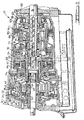
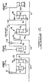
- FIGS. 1 and 2 of the drawings show a gear transmission adapted to transmit torque in one direction between a driving member and a driven member. It is indicated generally by reference numeral 10.
- a main transmission housing 12 encloses simple planetary gear units 16, 18 and 20.
- An input shaft 13 is connected to carrier 21 of first planetary gearset 16, which includes sun gear 22, a set of planetary pinions 24 rotatably supported on carrier 21 and ring gear 26.
- Sun gear 62 is drivably connected to a member 30 that is common to a coast clutch 32 and an overdrive brake 34.
- Ring gear 26 is drivably fixed to a drum portion 28 connected to intermediate shaft 36.
- Overdrive brake 34 includes a set of clutch discs fixed to housing 12, a load block 38 fixed to housing 12, a set of clutch discs drivably connected to the outer surface of clutch member 30 and interposed between the discs affixed to the housing, a clutch piston 40 displaceable hydraulically against the clutch disc assembly and hydraulic cylinder 42 containing piston 40.
- a Belleville spring 44 returns piston 40 to the inactive position when hydraulic pressure is removed from cylinder 42.
- Coast clutch 32 includes a set of clutch discs drivably connected to the inner surface of clutch member 30, a load block connected to the inner surface of clutch member 30, a second set of clutch discs drivably fixed to ring gear 26, piston 46 actuated hydraulically to engage the coast clutch disc sets, a hydraulic cylinder 48 within which piston 46 moves, and a Belleville spring 50 to return piston 46 to the disengaged position when hydraulic pressure is removed from cylinder 48.
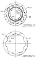
- a first one-way clutch 52 has its outer race 52A formed with an undulating profiled outer surface 112, as illustrated in Figures 3 and 4. It is drivably connected and in conjugate registration with a corresponding profiled inner surface 113 of ring gear 26.
- Clutch 52 has an inner race 52B drivably connected by a spline to cylinder 48 and to sun gear 22, and a driving member located in the annulus between the inner and outer races for producing a one-way clutch 54 is located between intermediate brake 56 and direct clutch 58.
- One-way clutch 54 includes an outer race that carries a set of brake discs for the intermediate brake 56, an inner race drivably fixed to drum 60, and a driving member located in the annular region between the inner and outer races for producing a one-way drive connection therebetween.
- the outer race of one-way clutch 54 has an undulating profile and the inner surface of intermediate brake 56 has a corresponding undulating profile as illustrated in Figures 3 and 4, for conjugate registration as hereinafter more fully described.
- Intermediate brake 56 includes a second set of brake discs fixed to housing 12, a load block fixed to the housing, a piston 61 actuated hydraulically to force the brake disc sets into drivable relationship against the load block, hydraulic cylinder 43 within which piston 61 moves and a Belleville spring.
- Drum 60 is stopped and held against the transmission casing through the action of an intermediate brake band 62 actuated via a conventional manner by a hydraulic transmission servo, not shown.
- Direct clutch 58 operates to produce a drive connection between drum 60 and clutch member 64.
- the direct clutch includes a first set of clutch discs splined to the inner surface of drum 60 and a second set of clutch discs connected to clutch member 64 which are interposed between successive members of the first clutch disc set.
- a piston 66 moves within a hydraulic cylinder to force the clutch disc sets into drivable connection against the load block that is carried on the inner surface of the drum 60. Piston 66 moves within the hydraulic cylinder defined by drum 60 and is restored to its disengaged position through operation of coil compression springs 68.
- Forward clutch 70 operates to produce a driving connection between clutch member 64 and the ring gear 72 of the second planetary gearset 18.
- This gearset includes a sun gear 74, a set of planetary pinions 76 in continual meshing engagement with sun gear 74 and ring gear 72, the latter being rotatably supported on a carrier 78 which is drivably connected by spline 80 to the tail shaft 14.
- Forward clutch 70 includes a first set of clutch discs drivably connected to the inner surface of clutch member 64 and a second set of clutch discs, each interposed with discs of the first set, drivably connected to the outer surface of ring gear 72.
- Piston 82 is hydraulically actuated for movement within the cylinder defined by clutch member 64 to force the clutch discs into a drivable connection.
- Belleville spring 84 returns piston 82 to the disengaged position when hydraulic pressure is removed from the clutch cylinder.
- the third planetary gear gearset 84 includes sun gear 86 formed integrally with sun gear 74, ring gear 88 connected by spline 90 to tailshaft 14, a set of planet pinions 92 rotatably supported on carrier 94, which is drivably connected to a first set of brake discs of the low-and-reverse brake 96.
- a second set of brake discs of brake 96 is fixed to transmission casing 12. Each disc of the second set is interposed between successive discs of the first disc set of brake 96.
- Brake piston 98 is actuated hydraulically when cylinder 100 is pressurized to force the piston against the first and second brake disc sets and to produce a drivable connection therebetween against the effect of the return spring 102.
- Spring 102 forces piston 98 to the brake disengaged position when cylinder 100 is vented.
- Load block 104, fixed to the transmission casing provides a reaction for the force applied by piston 138 to the disc brake sets.
- a third one-way clutch 106 includes an outer race having an undulating profile in conjugate registration with a correspondingly undulating profiled inner surface of carrier 94, illustrated in Figures 3 and 4, an inner race 110 bolted to the transmission casing 12, and a driving member located in the annular region between the inner and outer races to produce a one-way drive connection between carrier 94 and the casing.
- FIGS 3 and 4 illustrate one of the three one-way clutches 52, for purposes of illustration.
- clutch 52 includes concentric inner 52B and outer 52A race portions concentrically connected to ring gear 26.
- the outer surface 112 of outer race 52A has an undulating profile defined by a plurality of crests and troughs.
- the inner surface 113 of ring gear 26 has a corresponding undulating profile defined by a like plurality of crests and troughs.
- the profiles of the outer race outer surface 112 and ring gear inner surface 113 register in conjugate registration.
- the undulating profile is designed to provide a controlled clearance between the surfaces which provides a gradual lock-up of the surfaces through a wedging or ramping lock-up of the surfaces as rotational forces are communicated through the transmission 10.
- the gradual lock-up, through controlled wind-up eliminates shock loading and reduces torsional vibration in the gear elements upstream and downstream in the transmission.
- the same principle is used in clutch 54 and brake 106 connections.
- the connection hereinabove described is the outer race of a one-way clutch-transmission element connection, the connection can be utilized to connect the inner race of a one-way clutch to a mating transmission element.
- the profile of the crests and troughs is tailored to the application dynamics such as the deflected shape that mating circular surfaces seek when they are radially loaded to enhance and stabilize the one-way response of the clutches 52, 54 and brake 106.
- the wind-up through ramping lock-up eliminates the on/off locking engagement of splined connections and the associated shock loading upstream and downstream on transmission components as rotational forces are transmitted.
- the undulating surfaces 112,113 can be coated with a composite coating of a material such as an elastomeric plastic of synthetic rubber energizing material, or a thermoplastic engineering plastic composite material, either filled or unfilled with various reinforcing materials or fibers to dampen shock loading and further reduce vibration.
- a material such as an elastomeric plastic of synthetic rubber energizing material, or a thermoplastic engineering plastic composite material, either filled or unfilled with various reinforcing materials or fibers to dampen shock loading and further reduce vibration.
- plugs of the shock dampening material can be impregnated into the undulating surfaces 112,113.
Landscapes
- Engineering & Computer Science (AREA)
- General Engineering & Computer Science (AREA)
- Mechanical Engineering (AREA)
- Structure Of Transmissions (AREA)
- Retarders (AREA)
- Gear-Shifting Mechanisms (AREA)
- Gears, Cams (AREA)
- Mechanical Operated Clutches (AREA)
Applications Claiming Priority (2)
| Application Number | Priority Date | Filing Date | Title |
|---|---|---|---|
| US07/819,145 US5234390A (en) | 1992-01-09 | 1992-01-09 | Gear transmission with undulating surface clutch and brake element connections |
| US819145 | 1992-01-09 |
Publications (2)
| Publication Number | Publication Date |
|---|---|
| EP0550971A1 true EP0550971A1 (fr) | 1993-07-14 |
| EP0550971B1 EP0550971B1 (fr) | 1997-05-28 |
Family
ID=25227320
Family Applications (1)
| Application Number | Title | Priority Date | Filing Date |
|---|---|---|---|
| EP92310971A Expired - Lifetime EP0550971B1 (fr) | 1992-01-09 | 1992-12-01 | Engrenages de transmission comportant des éléments de freinage et d'embrayage fixés par une surface ondulée |
Country Status (7)
| Country | Link |
|---|---|
| US (1) | US5234390A (fr) |
| EP (1) | EP0550971B1 (fr) |
| JP (1) | JPH05256342A (fr) |
| KR (1) | KR930016689A (fr) |
| AU (1) | AU2980892A (fr) |
| CA (1) | CA2083912A1 (fr) |
| DE (1) | DE69220023T2 (fr) |
Cited By (2)
| Publication number | Priority date | Publication date | Assignee | Title |
|---|---|---|---|---|
| EP0740077A3 (fr) * | 1995-04-18 | 1998-05-06 | Kabushiki Kaisha Toyoda Jidoshokki Seisakusho | Compresseur de réfrigération avec unité de transmission de la force motrice |
| WO2003025411A1 (fr) * | 2001-09-07 | 2003-03-27 | Paul Müller Gmbh & Co. Kg | Roue libre dotee d'une bague exterieure entouree de plastique renforce par des fibres |
Families Citing this family (5)
| Publication number | Priority date | Publication date | Assignee | Title |
|---|---|---|---|---|
| FR2754578B1 (fr) * | 1996-10-14 | 1998-11-27 | Skf France | Dispositif de roue libre |
| US6053839A (en) * | 1999-06-18 | 2000-04-25 | Ford Global Technologies, Inc. | Multiple speed overdrive transmission for a motor vehicle |
| AUPQ969800A0 (en) * | 2000-08-28 | 2000-09-21 | Fujisawa Pharmaceutical Co., Ltd. | Pyrazolopyridine compound and pharmaceutical use thereof |
| US6481551B1 (en) * | 2000-11-27 | 2002-11-19 | Means Industries, Inc. | Inertia-actuated overrunning coupling assembly |
| KR100734481B1 (ko) * | 2001-11-22 | 2007-07-03 | 위니아만도 주식회사 | 빙수용 얼음알갱이 제조장치 |
Citations (2)
| Publication number | Priority date | Publication date | Assignee | Title |
|---|---|---|---|---|
| GB2149029A (en) * | 1983-10-11 | 1985-06-05 | Aisin Warner | One-way clutch or brake for automatic transmission |
| EP0347536A2 (fr) * | 1988-06-23 | 1989-12-27 | Ford-Werke Aktiengesellschaft | Transmission automatique à quatre vitesses |
Family Cites Families (18)
| Publication number | Priority date | Publication date | Assignee | Title |
|---|---|---|---|---|
| US288134A (en) * | 1883-11-06 | Gear-wheel | ||
| US1359468A (en) * | 1919-08-13 | 1920-11-16 | Schmidt Hermann | Free-wheel coaster-brake with friction-clutch |
| US1912703A (en) * | 1930-06-23 | 1933-06-06 | Borg & Beck Co | Driven plate for friction clutches |
| US2268376A (en) * | 1940-12-09 | 1941-12-30 | Adiel Y Dodge | One way clutch |
| US2639496A (en) * | 1945-03-14 | 1953-05-26 | Gen Motors Corp | Method of making shock absorbing connections |
| DE1144975B (de) * | 1960-07-21 | 1963-03-07 | Borg Warner | Klemmrollen-Freilaufkupplung und Verfahren zur Herstellung des Aussenteils einer solchen Kupplung |
| US3257860A (en) * | 1964-06-01 | 1966-06-28 | Burroughs Corp | Vibration and shock insulating sprocket |
| US3532198A (en) * | 1969-01-21 | 1970-10-06 | Gen Motors Corp | Sprag clutch |
| DE2065400A1 (de) * | 1970-04-30 | 1973-08-09 | Nissan Motor | Planetenwechselgetriebe mit mindestens drei saetzen |
| DE2023639A1 (de) * | 1970-05-14 | 1971-12-02 | Ford-Werke AG, 5000 Köln-Deutz | Hydrodynamisch-mechanisches Getriebe für Kraftfahrzeuge |
| JPS513853B2 (fr) * | 1972-06-14 | 1976-02-06 | ||
| GB1483727A (en) * | 1973-08-17 | 1977-08-24 | Volvo Ab | Compound epicyclic transmission systems |
| US4493407A (en) * | 1981-12-14 | 1985-01-15 | Warner Electric Brake & Clutch Company | Armature assembly for an electromagnetic clutch |
| JPS61192953A (ja) * | 1985-02-21 | 1986-08-27 | Nissan Motor Co Ltd | 自動変速機の遊星歯車列 |
| KR880001746B1 (ko) * | 1985-10-24 | 1988-09-10 | 하정용 | 변속기의 역회전 방지장치 |
| US4788874A (en) * | 1987-02-06 | 1988-12-06 | Nelson Bertel S | Differential clutch |
| US4821856A (en) * | 1987-11-16 | 1989-04-18 | General Motors Corporation | Overrunning roller clutch with roller control cars |
| US4993528A (en) * | 1990-05-04 | 1991-02-19 | General Motors Corporation | Multiple row roller clutch with roller control cars |
-
1992
- 1992-01-09 US US07/819,145 patent/US5234390A/en not_active Expired - Lifetime
- 1992-11-26 CA CA002083912A patent/CA2083912A1/fr not_active Abandoned
- 1992-12-01 DE DE69220023T patent/DE69220023T2/de not_active Expired - Fee Related
- 1992-12-01 AU AU29808/92A patent/AU2980892A/en not_active Abandoned
- 1992-12-01 EP EP92310971A patent/EP0550971B1/fr not_active Expired - Lifetime
-
1993
- 1993-01-06 KR KR1019930000058A patent/KR930016689A/ko not_active Withdrawn
- 1993-01-07 JP JP5001203A patent/JPH05256342A/ja active Pending
Patent Citations (2)
| Publication number | Priority date | Publication date | Assignee | Title |
|---|---|---|---|---|
| GB2149029A (en) * | 1983-10-11 | 1985-06-05 | Aisin Warner | One-way clutch or brake for automatic transmission |
| EP0347536A2 (fr) * | 1988-06-23 | 1989-12-27 | Ford-Werke Aktiengesellschaft | Transmission automatique à quatre vitesses |
Non-Patent Citations (2)
| Title |
|---|
| MACHINE DESIGN vol. 60, no. 18, 11 August 1988, CLEVELAND, OHIO, USA pages 124 - 127 DAVID RYFFEL 'A better way to make shaft connections' * |
| SOVIET INVENTIONS ILLUSTRATED Section PQ, Week 9249, 27 January 1993 Derwent Publications Ltd., London, GB; Class Q63, AN 92-405595 & SU-A-4 715 587 (NIKOLAEVSK MAKAROW SHIPBUILDING INST) 6 July 1989 * |
Cited By (4)
| Publication number | Priority date | Publication date | Assignee | Title |
|---|---|---|---|---|
| EP0740077A3 (fr) * | 1995-04-18 | 1998-05-06 | Kabushiki Kaisha Toyoda Jidoshokki Seisakusho | Compresseur de réfrigération avec unité de transmission de la force motrice |
| US6065943A (en) * | 1995-04-18 | 2000-05-23 | Denso Corporation | Refrigerant compressor having improved drive power transmission unit |
| WO2003025411A1 (fr) * | 2001-09-07 | 2003-03-27 | Paul Müller Gmbh & Co. Kg | Roue libre dotee d'une bague exterieure entouree de plastique renforce par des fibres |
| US7175011B2 (en) | 2001-09-07 | 2007-02-13 | Paul Mueller Gmbh & Co. Kg Unternehmensbeteiligungen | Free-wheel with a free-wheel outer rim covered with fiber-reinforced plastic |
Also Published As
| Publication number | Publication date |
|---|---|
| KR930016689A (ko) | 1993-08-26 |
| CA2083912A1 (fr) | 1993-07-10 |
| DE69220023T2 (de) | 1997-09-04 |
| AU2980892A (en) | 1993-07-15 |
| DE69220023D1 (de) | 1997-07-03 |
| EP0550971B1 (fr) | 1997-05-28 |
| US5234390A (en) | 1993-08-10 |
| JPH05256342A (ja) | 1993-10-05 |
Similar Documents
| Publication | Publication Date | Title |
|---|---|---|
| US4422535A (en) | Compound damper assembly for an automatic transmission | |
| US4509389A (en) | Four speed ratio transaxle with overdrive | |
| US6227340B1 (en) | Automatic transmission with dual gain multi-disk friction device | |
| EP0562381B1 (fr) | Transmission planétaire avec embrayage unidirectionnel débrayable | |
| US4978328A (en) | Automatic transaxle assembly for an automotive vehicle driveline | |
| US4452099A (en) | Three speed overdrive transaxle assembly | |
| WO1996001381A1 (fr) | Transmission automatique a cinq rapports | |
| US20060025278A1 (en) | Transmission devices, for ground vehicles and more particularly for motors-cars | |
| WO1996017188A1 (fr) | Transmission automatique a quatre vitesses | |
| EP0038538B1 (fr) | Transmission automatique à quatre vitesses de montage transversal | |
| GB1559491A (en) | Change speed gear boxes | |
| GB1574669A (en) | Torque converter and lockup clutch assemblies | |
| US4400998A (en) | Four speed overdrive transaxle | |
| US5188575A (en) | Automatic four-speed transmission with interconnected clutches | |
| AU766974B2 (en) | Power train for automatic transmissions | |
| US5129871A (en) | Nonsynchronous five-speed transaxle having bidirectional coupling | |
| US3710650A (en) | Planetary gear-change-speed transmission mechanisms | |
| EP0069981A2 (fr) | Transmission planétaire et moyens de montage pour l'arbre de sortie | |
| US4982826A (en) | Bleeder ball check valves in an automatic transmission | |
| WO1985001785A1 (fr) | Transmission hydromecanique avec couple divise et chemins d'ecoulement de couple regenerateurs | |
| US5511642A (en) | Overrunning clutch assembly | |
| GB2031075A (en) | Transmission mechanism | |
| US5234390A (en) | Gear transmission with undulating surface clutch and brake element connections | |
| US4142425A (en) | Multiple speed double planetary gear transmission | |
| US6095941A (en) | Overrunning clutch assembly |
Legal Events
| Date | Code | Title | Description |
|---|---|---|---|
| PUAI | Public reference made under article 153(3) epc to a published international application that has entered the european phase |
Free format text: ORIGINAL CODE: 0009012 |
|
| AK | Designated contracting states |
Kind code of ref document: A1 Designated state(s): DE ES FR GB IT |
|
| 17P | Request for examination filed |
Effective date: 19931019 |
|
| 17Q | First examination report despatched |
Effective date: 19940908 |
|
| GRAG | Despatch of communication of intention to grant |
Free format text: ORIGINAL CODE: EPIDOS AGRA |
|
| GRAH | Despatch of communication of intention to grant a patent |
Free format text: ORIGINAL CODE: EPIDOS IGRA |
|
| GRAH | Despatch of communication of intention to grant a patent |
Free format text: ORIGINAL CODE: EPIDOS IGRA |
|
| GRAH | Despatch of communication of intention to grant a patent |
Free format text: ORIGINAL CODE: EPIDOS IGRA |
|
| GRAA | (expected) grant |
Free format text: ORIGINAL CODE: 0009210 |
|
| AK | Designated contracting states |
Kind code of ref document: B1 Designated state(s): DE ES FR GB IT |
|
| PG25 | Lapsed in a contracting state [announced via postgrant information from national office to epo] |
Ref country code: IT Free format text: LAPSE BECAUSE OF FAILURE TO SUBMIT A TRANSLATION OF THE DESCRIPTION OR TO PAY THE FEE WITHIN THE PRE;WARNING: LAPSES OF ITALIAN PATENTS WITH EFFECTIVE DATE BEFORE 2007 MAY HAVE OCCURRED AT ANY TIME BEFORE 2007. THE CORRECT EFFECTIVE DATE MAY BE DIFFERENT FROM THE ONE RECORDED.SCRIBED TIME-LIMIT Effective date: 19970528 Ref country code: ES Free format text: THE PATENT HAS BEEN ANNULLED BY A DECISION OF A NATIONAL AUTHORITY Effective date: 19970528 |
|
| REF | Corresponds to: |
Ref document number: 69220023 Country of ref document: DE Date of ref document: 19970703 |
|
| ET | Fr: translation filed | ||
| PLBE | No opposition filed within time limit |
Free format text: ORIGINAL CODE: 0009261 |
|
| 26N | No opposition filed | ||
| REG | Reference to a national code |
Ref country code: GB Ref legal event code: IF02 |
|
| PGFP | Annual fee paid to national office [announced via postgrant information from national office to epo] |
Ref country code: FR Payment date: 20081205 Year of fee payment: 17 |
|
| PGFP | Annual fee paid to national office [announced via postgrant information from national office to epo] |
Ref country code: DE Payment date: 20081230 Year of fee payment: 17 |
|
| PGFP | Annual fee paid to national office [announced via postgrant information from national office to epo] |
Ref country code: GB Payment date: 20081110 Year of fee payment: 17 |
|
| GBPC | Gb: european patent ceased through non-payment of renewal fee |
Effective date: 20091201 |
|
| REG | Reference to a national code |
Ref country code: FR Ref legal event code: ST Effective date: 20100831 |
|
| PG25 | Lapsed in a contracting state [announced via postgrant information from national office to epo] |
Ref country code: FR Free format text: LAPSE BECAUSE OF NON-PAYMENT OF DUE FEES Effective date: 20091231 |
|
| PG25 | Lapsed in a contracting state [announced via postgrant information from national office to epo] |
Ref country code: DE Free format text: LAPSE BECAUSE OF NON-PAYMENT OF DUE FEES Effective date: 20100701 |
|
| PG25 | Lapsed in a contracting state [announced via postgrant information from national office to epo] |
Ref country code: GB Free format text: LAPSE BECAUSE OF NON-PAYMENT OF DUE FEES Effective date: 20091201 |