EP0551937A1 - Anordnung zur Messung der Qualität einer Übertragung in einer Zweidrahtleitung mit Echolöschung - Google Patents
Anordnung zur Messung der Qualität einer Übertragung in einer Zweidrahtleitung mit Echolöschung Download PDFInfo
- Publication number
- EP0551937A1 EP0551937A1 EP93200016A EP93200016A EP0551937A1 EP 0551937 A1 EP0551937 A1 EP 0551937A1 EP 93200016 A EP93200016 A EP 93200016A EP 93200016 A EP93200016 A EP 93200016A EP 0551937 A1 EP0551937 A1 EP 0551937A1
- Authority
- EP
- European Patent Office
- Prior art keywords
- errors
- line
- online
- transmission
- numbers
- Prior art date
- Legal status (The legal status is an assumption and is not a legal conclusion. Google has not performed a legal analysis and makes no representation as to the accuracy of the status listed.)
- Granted
Links
- 230000005540 biological transmission Effects 0.000 title claims abstract description 122
- 238000005259 measurement Methods 0.000 claims abstract description 56
- 238000012545 processing Methods 0.000 claims abstract description 18
- 230000002457 bidirectional effect Effects 0.000 claims abstract description 12
- 238000000034 method Methods 0.000 claims description 37
- 230000004044 response Effects 0.000 claims description 7
- 230000011664 signaling Effects 0.000 claims description 2
- 238000012546 transfer Methods 0.000 abstract description 15
- 230000006870 function Effects 0.000 description 21
- 238000001514 detection method Methods 0.000 description 15
- 238000009434 installation Methods 0.000 description 11
- 230000004913 activation Effects 0.000 description 10
- 238000010586 diagram Methods 0.000 description 10
- 238000003780 insertion Methods 0.000 description 5
- 230000037431 insertion Effects 0.000 description 5
- 230000008569 process Effects 0.000 description 4
- 238000010719 annulation reaction Methods 0.000 description 3
- 230000001360 synchronised effect Effects 0.000 description 3
- 241000897276 Termes Species 0.000 description 2
- 230000008878 coupling Effects 0.000 description 2
- 238000010168 coupling process Methods 0.000 description 2
- 238000005859 coupling reaction Methods 0.000 description 2
- 230000009849 deactivation Effects 0.000 description 2
- 230000010354 integration Effects 0.000 description 2
- 238000012423 maintenance Methods 0.000 description 2
- 230000033764 rhythmic process Effects 0.000 description 2
- 238000005070 sampling Methods 0.000 description 2
- 239000000243 solution Substances 0.000 description 2
- 238000010200 validation analysis Methods 0.000 description 2
- 102100031437 Cell cycle checkpoint protein RAD1 Human genes 0.000 description 1
- 101001130384 Homo sapiens Cell cycle checkpoint protein RAD1 Proteins 0.000 description 1
- 230000003213 activating effect Effects 0.000 description 1
- 238000004458 analytical method Methods 0.000 description 1
- 238000004364 calculation method Methods 0.000 description 1
- 230000015556 catabolic process Effects 0.000 description 1
- 125000004122 cyclic group Chemical group 0.000 description 1
- 238000006731 degradation reaction Methods 0.000 description 1
- 238000013461 design Methods 0.000 description 1
- 238000000605 extraction Methods 0.000 description 1
- 238000002347 injection Methods 0.000 description 1
- 239000007924 injection Substances 0.000 description 1
- 238000004519 manufacturing process Methods 0.000 description 1
- 238000012986 modification Methods 0.000 description 1
- 230000004048 modification Effects 0.000 description 1
- 238000012544 monitoring process Methods 0.000 description 1
- 230000000737 periodic effect Effects 0.000 description 1
- 238000011084 recovery Methods 0.000 description 1
- 230000035945 sensitivity Effects 0.000 description 1
- 230000003595 spectral effect Effects 0.000 description 1
- 238000012360 testing method Methods 0.000 description 1
- 238000010396 two-hybrid screening Methods 0.000 description 1
- 238000004804 winding Methods 0.000 description 1
Images



Classifications
-
- H—ELECTRICITY
- H04—ELECTRIC COMMUNICATION TECHNIQUE
- H04L—TRANSMISSION OF DIGITAL INFORMATION, e.g. TELEGRAPHIC COMMUNICATION
- H04L1/00—Arrangements for detecting or preventing errors in the information received
- H04L1/20—Arrangements for detecting or preventing errors in the information received using signal quality detector
Definitions
- the present invention relates, in general, to measurements of transmission quality in a two-wire line with echo cancellation.
- ISDN Digital Integrated Services Network
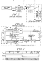
- First and second terminals TE1 and TE2 are located at the ends of a two-wire transmission line LT and transmit and receive digital data. Thus the two directions of transmission take the same line with two wires.
- a digital signal E2 (t) coming from the transmission part EM2 of the second terminal TE2 is disturbed, through a coupler, such as a differential transformer, between the transmission and reception parts EM1 and REC1 in the first terminal TE1 , by an echo signal of a signal emitted E1 (t) by the EM1 part.
- This echo mainly breaks down into a local echo (imperfect equilibrium of the coupler in the first terminal TE1) and a distant echo (poor impedance matching at the coupler of the second terminal TE2). It is therefore necessary to subtract from the total signal received the echo signal in order to reconstruct the signal sent by the second terminal.
- AN1 echo canceller included in the first terminal establishes a "replica" of the echo signal note from the signal emitted E1 (t).
- the canceller is produced in the form of a digital filter comprising a delay line with N stages, memorizing the successive samples taken at the rate 1 / T of the signal emitted E1 (t). These are weighted by a set of N coefficients so as to reproduce the amplitude and the delay of the real echo In addition, the values of these coefficients are automatically adjusted according to an error signal.
- an online code commonly known as 4B3T (alphabetic code), defined by the CCITT, is in the process of becoming an international standard and an appropriate procedure for detecting errors is associated with it.
- This error detection is carried out at a line terminal which is located in a telephone exchange and which detects transmission errors linked to disturbances in a two-wire line serving a network terminal preceding a telephone installation by subscriber.
- the line terminal only has error information relating to the error detection procedure, chosen precisely according to the online code. A "real" measurement, in the sense of bit error rate, is therefore not obtained.
- the transmission quality of a line for an ISDN subscriber installation is only measured for a period of twenty-four hours before the line is put into service by looping it.
- This commissioning is effective if the result of the measurement complies with Recommendation G.821 defined by the CCITT, fascicle III.5, pages 26 to 35, Geneva 1980. Except for this commissioning procedure, no quality information is only accessible to the network operator as well as the subscriber. This quality information is only available at the home exchange in the central office to possibly break a link when the transmission quality is too degraded.
- This quality information is representative of the transmission quality state in the line, without giving an exact measurement of this.
- the present invention aims to remedy the aforementioned drawbacks according to the prior art by making it possible to measure a real quality of transmission in the line, independently of the error detection procedure, this measurement being able to be carried out at any time.
- the measurement device uses bidirectional transmission circuits taking up repeater type functions while being transparent to the data conveyed in the line.
- the line can be a subscriber transmission line at the U interface between a subscriber installation terminal and a link transmission termination of the home exchange.
- the binary data passing between the first and second transmission circuits of the measurement device are then structured in binary frames each comprising at least one terminal monitor channel field in which a read command word is entered periodically and an error number online is collected periodically.
- the measuring device comprises means for interconnecting it removably to the transmission line, in a telephone exchange distributor serving said line.
- the invention also relates to a quality measurement correlation system, further comprising the measurement device according to the invention, in order to compare error numbers relating to the data online and error numbers relating to the data binaries according to a known procedure.
- the measurement device is then located near the first terminal, such as the home branch exchange switching terminal, to periodically acquire online error numbers relating to the line code data transmitted from the second to the first terminal.
- the correlation system then comprises means connected to the first terminal for transmitting first binary data to the second terminal and receiving second binary data transmitted by the second terminal and originating from the first data by looping back into the second terminal, means for comparing the first and second data to periodically establish bit error numbers, and means for correlating the online error numbers and the bit error numbers.
- the method is such that the average of the numbers of binary errors per online error is established, and such averages are established as a function of noise characteristics disturbing the transmission line respectively.
- the numbers of errors can be selected according to thresholds in order to define parameters relating to both online errors and binary errors and to correlate said parameters of online errors and binary errors with each other.
- the description below relates to ISDN digital systems, called second generation.
- a two-wire line transmission chain of a local network, or of distribution, connecting a subscriber installation to an automatic branch exchange AR of a telephone exchange typically comprises, in the context ISDN TNR network terminal, transmission line two-wire LT, and a line terminal TL.
- the TNR network terminal is connected to one of the switching terminals of the PABX through the line terminal TL.
- the physical link between the TNR network terminal and the line terminal TL consists of the two-wire subscriber line LT and one of the connection means, called connection strip REG, of a distributor RE of the telephone exchange.
- connection strip REG connection means
- Each subscriber line is thus associated with an input-output of the automatic exchange according to the strip to which it is fixed.
- the strip is commonly used to connect various measurement and line test means.
- the functional links existing at the U interface, between the TNR network and line TL terminals ensure the bidirectional transmission of useful information carried by digital channels B and D of an ISDN frame, typically at 64 kbit / s and 16 kbit. / s, and fulfill synchronization functions, activation and deactivation functions of the subscriber's digital transmission line up to the interface T, between the subscriber installation and the TNR network terminal, operation and maintenance functions and finally remote power supply functions of the TNR network terminal.
- circuit U a transmission / reception circuit for interface U, hereinafter called circuit U, of which a good understanding of the operation is necessary to grasp the characteristics of the device for measuring quality according to the invention. Due to the symmetry of the transmission chain between the TNR and TL terminals, due to bidirectional processing, two identical U circuits are respectively included in the TNR network terminal and the TL line terminal and ensure the implementation of the interface U, as shown in Figure 2.
- the network terminal TNR also includes a transmission / reception circuit for the T interface, hereinafter called the T circuit, in order to be interfaced with the subscriber installation in accordance with the standards defining this interface.
- the line terminal TL is connected to the associated switching terminal of the home exchange via the interface V.
- circuits U have been standardized, using an interface called "system interface" IS, compatible with interface V.
- system interface IS
- a circuit U and a circuit T can be connected by means of this system interface.
- the system interface provided at circuit U serves as a quasi-direct interface with the switching terminal. It will be seen later that, in fact, the functional difference between the circuits U used for the network and line terminals lies in the programming of certain circuits which they include. Depending on certain intrinsic characteristics of the ISDN network chosen by operators, the system interface can provide specific functions adapted to national standards for activating and maintaining the transmission chain.
- the operator of the French telephone network having chosen a permanent activation of the U interface to monitor the quality of the links, and an activation on demand of the T interface, between TNR network terminal and installation of subscribers, it is proceeded , when the transmission chain is put into operation, when the TNR network terminal is activated with loopback in circuit T, then deactivation of circuit T and unwinding with maintenance of activation of circuit U by said specific functions.
- a transmission / reception circuit for interface U mainly comprises, in a transmission channel, a scrambler EM, a coder COD, a multiplexer MUX, a digital-analog converter DAC, and a transmission amplifier.
- AMP and in a reception channel, an analog-digital converter CAN, a subtractor SO, an equalizer EG, a demultiplexer DEMUX, a decoder DEC and a descrambler DEB.
- the terms "transmission” and "reception” relate to the interface U.
- a hybrid coupler CO connects the amplifier AMP and the CAN converter of the transmission and reception channels to the two-wire line LT.
- An echo canceller AN implements echo cancellation functions as presented in the preamble of the description with reference to FIG. 1.
- a management and activation circuit CGA is connected in particular to the equalizer EG , to the MUX multiplexer and DEMUX demultiplexer and in particular ensures the synchronization of the frames at the U interface as well as the activation of this interface.
- a bidirectional channel CT transparent at the U interface is used for the dialogue between the AR branch exchange and the TNR network terminal.
- the multiplexer MUX multiplexes in each frame to be transmitted, a synchronization word MS supplied by the circuit CGA, the transparent channel CT, and the channels 2B + D scrambled and coded by the scrambler EM and the coder COD.
- the code is for example the code 4B-3T, code which will be presented later in the description.
- the synchronization word MS in a frame received by the demultiplexer DEM is used by recovery means rhythm included in the CGA circuit to reconstruct the frame and establish various clock signals HO.
- the content of the transparent channel CT is not used at the interface U, and is transmitted from the automatic branch exchange AR to the circuit T of the terminal TNR via the demultiplexer DEM for an activation or a loopback command.
- the transmission circuit for U interface includes a system interface adapter AD which, as previously reported, "standardizes" the manufacture of circuit U, that it is included at interface U in the terminal TNR network or in the TL line terminal.
- the interface adapter AD is connected to an interface adapter in the transmission circuit for interface T of the TNR terminal.
- this adapter is connected via the interface V to the associated switching terminal of the home exchange PABX.
- such transmission circuits for U interface include physical interface functions proper with the two-wire subscriber line.
- the coupler CO relating to circuit U in FIG. 3 is included, in practice, in a line interface circuit comprising protection circuits against overvoltage and overcurrent, a differential line transformer and a means for extracting a current from TNR terminal remote power supply.
- the line interface circuit further comprises means for injecting remote supply current into the line LT in the direction of the network terminal TNR.
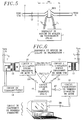
- FIG. 5 The interconnection of a transmission quality measurement device 1 according to the invention at the RE of the telephone exchange is shown in Figure 5.
- the insertion of the device 1 "in cascade" through the two-way line wires LT connecting the network terminal TNR to the line terminal TL is carried out in a removable manner, at the level of one REG of the strips of the distributor according to a known principle.
- the device 1 is thus introduced into the subscriber line by means of two pairs of connecting wires 10 and 11 between the slider REG and the device 1, to carry out a quality measurement.
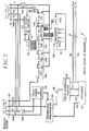
- the transmission quality measuring device 1 comprises two bidirectional transmission circuits for U interface 10 and 11, two hybrid protection and coupling means shown here by differential transformers 12 and 13, a remote power supply circuit 14, a transfer logic circuit 15, a number acquisition circuit d line errors 16, and an error number processing circuit 17.
- the first circuit U 10 is connected to the two-wire subscriber line, by means of the two connection wires 10, through the transformer 12.
- the remote supply circuit 14 supplies the line LT in the direction of the TNR network terminal by means of a capacitive coupling in the primary winding of the transformer 12.
- the second U 11 circuit is connected to the subscriber line through the transformer 13 and the two connecting wires 11.
- the two circuits 10 and 11 provide, as already indicated, two IS system interfaces materialized by ISO and IS1 four-wire buses connected to the transfer logic circuit 15.
- the number acquisition circuit 16 essentially including a RAM memory, stores numbers taken and established by the transfer logic circuit 15 and transferred by a bidirectional transfer bus BT composed of a data bus BD and an address bus BA.
- the two transmission circuits for interface U 10 and 11 are similar to that presented in FIG. 3. As indicated during the description of this circuit, the latter has an interface, called system interface, which is standardized, and can therefore be integrated either in the TL line terminal or in the TNR network terminal.
- This online ternary code associates three ternary symbols with 4 binary elements, a reverse operation being carried out with decoding.
- the following table summarizes the principle of coding: Binary elements Symb. Tern (1) AS Symb. Tern (2) AS Symb. Tern (3) AS Symb.
- the signs +, - and 0 designate the three symbols of the ternary code.
- a first column of the table gives all the words with four binary elements each. Four columns numbered from 1 to 4 are word alphabets with three ternary symbols to be associated respectively with words with four binary elements.
- the alphabet used for coding a binary quartet word depends on the algebraic sum of the three previously transmitted ternary symbols.
- the number AS of the following alphabet which is to be used for the next ternary word is thus indicated to the right of the transmitted ternary word, in the table above. Except during an initialization of the procedure, the number of a following alphabet to encode the following four binary elements is obtained by the current algebraic sum of the three current ternary elements.
- the successive words: "1001", “1001”, “1111” and “1100”, assuming that the first alphabet (1) is chosen for the initial coding of the first binary word “1001”, will be respectively coded "+ - +” implying the numbered alphabet (2) for the next word “1001”, in “+ - +” implying the numbered alphabet (3) for the next word "1111”, in “0 0 - "involving the numbered alphabet (2) for the next word” 1100 ", and in” - + - "implying the numbered alphabet (1) for coding the next binary word.
- a "natural" procedure for detecting errors in transmission in the subscriber line LT, at the interface U, is then implemented by programming the circuit U in the line terminal TL which, from the algebraic sum current resulting from the ternary words received in code 4B3T, increments an online error counter included in the CGA circuit when this sum is equal to 0 or strictly greater than 4.
- An incrementation of the counter results from an incorrect ternary symbol and therefore d an online error, knowing that the coding algorithm is designed so that the current algebraic sum is always between 1 and 4.
- online errors are detected only in one or both channels useful information CB1 and CB2.
- a preliminary phase of convergence of the coefficients in the echo cancellers of the two circuits 10 and 11 is necessary. It consists of two successive transmission periods allocated to circuit 10 and 11 so that each circuit U 10 and 11 measures the echo of its transmitted signal which is reflected within the echo canceller of circuit U by a calculation d a vector of coefficients which is used to subtract on reception from the global signal received all that is not information transmitted by the circuit and returned by echo, as described in the preamble of the description.
- the protection and remote supply functions have been presented previously and are established in particular by transformers 12 and 13 and the remote supply circuit 14.
- the circuits 10 and 11 ensure echo cancellations respectively with respect to the TNR network terminal and the TL line terminal.
- the two circuits 10 and 11 are of the standardized type, and only their programming differentiates them.
- the circuit 10 is programmed in line terminal TL mode, in particular to integrate a specific procedure for detecting online errors, similar to that also implemented at the line terminal TL.
- the circuit 10 notably comprises an echo subtractor means SO which is located in a reception channel of the circuit 10 receiving data in line code from the terminal TNR.
- a procedure of the type presented previously for the 4B3T code leads to the incrementation of a counter in the TL terminal when an online error is detected.
- the number of online errors stored in the counter is used by the automatic branch exchange AR to possibly break a link when the transmission quality is too degraded.
- the circuit 10 programmed in line terminal mode 10 includes means for detecting and counting online errors connected to the reception channel of the circuit 10 and in particular comprising a counter recording a number of online errors. This number of online errors depends on the online error detection procedure, which depends on the coding, but does not give a measure of the real quality of transmission, in the sense bit error rate.
- the transfer logic circuit 15 is connected to the two system interface adapters AS in the transmission circuits 10 and 11 by means of two four-wire buses ISO and IS1. Two wires of the bus IS1 supply a clock signal H and a frame clock signal FRAME necessary for the synchronous operation of the circuit 15 and of the circuit 10. Two system interfaces IS are thus established by the circuit 15 respectively with the two circuits 10 and 11.
- the frame at a system interface further comprises a monitor channel CM and a monitor channel enable channel CV. These two channels are used mainly by the transfer logic circuit 15 to read and take error numbers online in the error counter of the circuit 10 programmed for this purpose.
- Such a meter reading in the line terminal TL in an ISDN transmission chain is usually carried out by the automatic branch exchange AR to monitor the transmission quality via the monitor channel CM of the interface V.
- the error indicators in line established by the latter counter are not accessible by the network operator.
- the operation of reading the online error counter of the means for detecting and counting errors in the circuit 10 by the transfer logic circuit 15 consists in validating the monitor channel by transmitting a bit "0" in the CV validation channel as well as in the transmission of a counter read command word in the monitor channel CM.
- the monitor channel validation bit and the read command word are transmitted in a binary data frame carried by the wire D IN , entering the system interface adapter in circuit 10.
- the programmed circuit 10 in TL mode transmits the number online errors in binary form read in the counter, in the CM monitor channel on the D OUT wire coming out of the system interface adapter.
- the circuit 15 has, per period of transmission of command to read the counter and also to reset the counter to zero, of the order of a second for example, of number of online errors totaled in the counter of the circuit 10. These numbers of online errors are written in the data acquisition circuit 16 by the circuit 15 via the transfer bus BT.
- the data processing circuit 17 has, through the bus BR, numbers of online errors read periodically in the counter and stored in the circuit 16.
- the processing circuit 17 can then measure the transmission quality online as a function of these numbers of online errors which, as already said, do not represent the real quality of transmission since they are a function of the coding on the line and more precisely of the error detection procedure, chosen in function of this coding.
- the counter in circuit 10 instead of determining an error in a ternary word online as specified with reference to the table of alphabets above, the counter in circuit 10 detects errors in ternary blocks for example having a frame length or multiple frames.
- the transfer logic circuit 15 comprises a processor 151, a parallel interface circuit 152, a first counting logic circuit 153, a frequency divider 153a, a serial-parallel converter 154, a second circuit counting logic 155, a frequency divider 155a, an 8-bit memory 156, a comparator 157a, a 4-bit memory 157b, and four shift registers 158a to 158d of eight bits.
- the two frequency dividers 153a and 155a are frequency dividers by two and divide the frequency of the clock signal H in the system interface buses IS1 and IS2 by two into data clock signals H / 2 each having a frequency equal to the frequency of the incoming and outgoing data in the interface adapters of circuits 10 and 11.
- the data and frame clock signals, H and FRAME, illustrated in FIG. 4 are transmitted from circuit 11 to circuit 10, via buses IS1 and ISO, so that the "slave" circuit 10 is synchronized with the "master” circuit 11, in a manner analogous to the direct synchronization of circuit U in the TNR network terminal by the circuit U in the line terminal TL, in the absence of device 1.
- circuits 155 to 158d establish a read command word to be transmitted in the monitor channel CM.
- the four shift registers 158a to 158d with eight stages of flip-flops D each impose a delay of a frame at 32 bits (FIG. 4) on the binary data transmitted from the line terminal TL via circuit 11 and the wire D OUT in the bus IS1 to the TNR network terminal via the D IN wire of the ISO bus and circuit 10, temporarily storing them and shifting them to the frequency of the H / 2 data clock signal.
- the counting logic circuit 155 receives the frame clock signal FRAME and counts 32 periods of the data clock signal H / 2 of the bus IS1 after the start of a frame, in order to control the reading of the read-only memory 156 containing a read command word "11101111” (EF in hexadecimal code) and load this in the shift register 158c containing the 8-bit field of the monitor channel CM during reading. Simultaneously, the counting circuit 155 introduces a bit "0" in the first stage of register 158d and therefore in the CV channel field. Thus, the detection of the 8 bits "11101111" of the monitor channel by the management circuit of circuit 10 controls the reading of the counter in circuit 10.
- Comparator 157a and memory 157b are used for the control channel and C / I indication at the system interface.
- this C / I activation channel is used in particular by the automatic branch exchange AR to command a looping of control of the reception and transmission channels in the T circuit of the TNR network terminal.
- the transmission circuit for interface U of the TNR network terminal receives a 4-bit looping control word at "1010” and transcodes it into a transcoded word "1110" controlling a looping means of circuit U.
- Circuit 11 of the device 1 according to the invention programmed in TNR network terminal mode, operates this same transcoding.
- the comparator 157a compares the outputs of four flip-flops central register 158d corresponding to the field of the C / I channel with four bits "1110".
- the comparator 157a reads the read-only memory 157b to write the four-bit looping control word "1010" in the four flip-flops of the register 158d which thus ensures the transparency of the device 1.
- the latter In response to reading the online error counter in circuit U 10 programmed in terminal mode TNR network, the latter transfers a number of online errors coded in 8 bits and read in the counter then written in the field of the monitor channel CM carried by the wire D OUT of the ISO system interface.
- the serial-parallel buffer converter 154 samples and converts the number of online errors read received in serialized form in the wire D OUT of the ISO bus into a word with 8 parallel bits applied to the parallel interface circuit 152. This sampling is validated by the counting logic circuit 153 in response to 24 periods of the clock signal H / 2 (FIG. 4) succeeding the signal FRAME relating to the frames transmitted from the wire D OUT of the ISO bus of circuit 10 to the wire D IN of the bus IS1 of circuit 11.
- the processor 151 after an interrupt signal INT generated by the interface circuit 152 when receiving a number of errors read from the counter of the circuit 10, transfers the number of online errors read into a register from the interface circuit 152 to the data acquisition circuit 16 via the transfer bus BT, and resets (reset) the converter 154.
- the data acquisition circuit 16 After a predetermined number of periodic readings of online error numbers established by the counter of the circuit 10, for example approximately every second, the data acquisition circuit 16 has a series of online error numbers read at different moments.
- each number of online errors is not representative of a number of real binary errors after decoding, but only of online errors detected according to the online error detection procedure implemented in circuit 10, this procedure depending on the online code between the TNR network and TL line terminals.
- a correlation is established between the numbers of online errors and the numbers of binary errors.
- Recommendation G.821 specifies the transmission quality taking into account the degradation of the transmitted data, and in particular the distribution of bit errors over time. Commissioning of a transmission chain for a subscriber installation follows the coding and transmission at the line terminal TL of a pseudo-random binary sequence in a B channel which is compared with a binary sequence returned through a loop in the TNR network terminal and received and decoded by the TL terminal. Commissioning is effective if this comparison gives results in accordance with quality objectives defined in recommendation G.821, these objectives constituting percentages of the parameters defined above with respect to a predetermined commissioning measurement time, typically twenty four hours.
- the data processing circuit 17 is programmed as a function of experimental data to make a correlation between numbers of online errors read in circuit 16 and corresponding numbers of binary errors relating to the same measurement periods.
- FIG. 8 shows a quality measurement correlation system according to the invention, based on this last remark.
- This figure shows a transmission chain including a TNR network terminal and a TL line terminal connected by a 2-wire subscriber line LT through the interface U.
- the quality measurement device 1 is interconnected in the RE dispatcher.
- a pseudo-random transceiver ER transmits and receives binary data of channel B after looping of these in the network terminal TNR by means of a looping circuit BO.
- the binary data received after decoding is processed by a CTG processing circuit which performs quality parameter measurements relating to binary errors during periods of time equal to either the second or the minute, in accordance with recommendation G.821, and which transmits the result of these measurements from circuit 17 to the device 1.
- Noise generation means GB are intended to generate noise affecting the quality of the transmission. Since noise disturbs the transmission in the line, a correlation between the number of binary errors within the meaning of recommendation G.821 and the number of online errors produced in the circuit 10 of the device 1 can be established.
- the recommendation G.821 referring to minimum periods of one second, the reading of the on-line error counter of circuit 10, via the monitor channel CM, is carried out for each period of one second.
- the first noise defined above is analyzed below.
- the noise generation means GB (FIG. 8) generate an impulsive noise having a general form of signal presented in FIG. 9.
- This noise is injected by the means GB into the line LT. Since the processing circuit CTG and the measuring device 1 are synchronized in time intervals of one second and therefore of one minute, the CTG circuit and the device 1 establish respectively the average numbers of binary errors and the average numbers d errors online for successive one second time intervals making up a given measurement duration in order to respectively calculate average numbers of online errors and the three binary error parameters relating to the noise injected during the same measurement period .
- the circuit 17 of the device 1 finds that on average, the online error parameter SAE corresponds to the counting of N errors defined according to the detection procedure d 'errors online during each successive second of the measurement time.
- these measures are extended to the SGE and MD online error parameters. Average numbers of online errors established for the three parameters SAE, SGE and MD validated over the time intervals, seconds and minutes, of the measurement duration are thus obtained.
- the processing circuit CTG Simultaneously for each of the time intervals following which an online error parameter is validated, the processing circuit CTG also calculates a number of binary errors in the data received during this time interval. An average number of bit errors during the measurement duration for each G.821 bit error parameter is then deduced in the CTG circuit.
- circuit 17 in which the online error numbers and the binary error numbers are repatriated, then correlate the two types of measurement in terms of relationships N i between the number of binary errors P i and the number of errors online N i respectively calculated for the I time intervals of the measurement duration, these reports defining numbers of binary errors per online error for each validated parameter. Then circuit 17 calculates the average value of these ratios, i being an integer between 1 and the number I of time intervals of the measurement duration for the parameter considered. Circuit 17 thus establishes three average values relating respectively to the three parameters SAE, SGE and MD.
- FIGS. 10A and 10B show experimental curves representing respectively the variations of the average number of online errors counted by time intervals and of the average value of numbers of binary errors per online error, as a function of the pulse amplitude A of the impulsive noise represented in FIG. 9 for each of the three parameters SAE, SGE and MD.
- the values of the amplitude A belong to a range representative of the impulsive noise which can affect a line.
- measurements are made for various typical noises disturbing the subscriber transmission line LT and representative of the environments of the subscriber line during its actual operation, such as resulting from telephone, or electric or radio lines, close to the LT line, resulting from domestic or industrial machines close to the LT line, etc.
- the data processing circuit 17 stores, as a function of a given environment of the subscriber line, a quality measurement of which is desired, data relating to the environment of the type presented with reference to FIGS. 10A and 10B.
- the logic processing circuit 15 reads the counter of circuit 10 every second and transfers online error numbers read from the counter to the acquisition circuit 16 where they are stored.
- the data processing circuit 17 processes these numbers of online errors to deduce a quality measurement in terms of parameters of online errors and binary errors and numbers. means of binary errors by mistake online for each of the three parameters, and possibly for other parameters and measurement statistics.
- circuits 151 to 154 will then be used in order to carry out this sampling without of course requiring the insertion of any read command in a channel field.
Landscapes
- Engineering & Computer Science (AREA)
- Quality & Reliability (AREA)
- Computer Networks & Wireless Communication (AREA)
- Signal Processing (AREA)
- Monitoring And Testing Of Exchanges (AREA)
- Monitoring And Testing Of Transmission In General (AREA)
- Detection And Prevention Of Errors In Transmission (AREA)
Applications Claiming Priority (2)
| Application Number | Priority Date | Filing Date | Title |
|---|---|---|---|
| FR9200313 | 1992-01-14 | ||
| FR9200313A FR2686201B1 (fr) | 1992-01-14 | 1992-01-14 | Dispositif de mesure de qualite de transmission dans une ligne a deux fils avec annulation d'echo. |
Publications (2)
| Publication Number | Publication Date |
|---|---|
| EP0551937A1 true EP0551937A1 (de) | 1993-07-21 |
| EP0551937B1 EP0551937B1 (de) | 1996-11-13 |
Family
ID=9425614
Family Applications (1)
| Application Number | Title | Priority Date | Filing Date |
|---|---|---|---|
| EP19930200016 Expired - Lifetime EP0551937B1 (de) | 1992-01-14 | 1993-01-06 | Anordnung zur Messung der Qualität einer Übertragung in einer Zweidrahtleitung mit Echolöschung |
Country Status (4)
| Country | Link |
|---|---|
| EP (1) | EP0551937B1 (de) |
| DE (1) | DE69305872T2 (de) |
| ES (1) | ES2094455T3 (de) |
| FR (1) | FR2686201B1 (de) |
Cited By (2)
| Publication number | Priority date | Publication date | Assignee | Title |
|---|---|---|---|---|
| RU2304847C2 (ru) * | 2005-10-31 | 2007-08-20 | Общество с ограниченной ответственностью научно-производственное объединение "Волакс" | Устройство для автоматизированного контроля линии связи канала передачи данных |
| CN108811041A (zh) * | 2012-07-03 | 2018-11-13 | 交互数字专利控股公司 | 在无线站中使用的用于快速初始链路建立的方法及无线站 |
Families Citing this family (1)
| Publication number | Priority date | Publication date | Assignee | Title |
|---|---|---|---|---|
| RU2251723C2 (ru) * | 2003-06-26 | 2005-05-10 | Власов Валерий Иванович | Устройство для контроля качества линии связи канала передачи данных |
Citations (3)
| Publication number | Priority date | Publication date | Assignee | Title |
|---|---|---|---|---|
| FR2399162A1 (fr) * | 1977-07-29 | 1979-02-23 | Telecommunications Sa | Procede de localisation de fautes pour repartiteur de voies de donnees et son dispositif de mise en oeuvre |
| GB2190566A (en) * | 1986-05-16 | 1987-11-18 | Plessey Co Plc | Terminal apparatus |
| US4891813A (en) * | 1988-01-29 | 1990-01-02 | Racal Data Communications Inc. | Passive bus communication using alternate CRC |
-
1992
- 1992-01-14 FR FR9200313A patent/FR2686201B1/fr not_active Expired - Fee Related
-
1993
- 1993-01-06 DE DE1993605872 patent/DE69305872T2/de not_active Expired - Fee Related
- 1993-01-06 ES ES93200016T patent/ES2094455T3/es not_active Expired - Lifetime
- 1993-01-06 EP EP19930200016 patent/EP0551937B1/de not_active Expired - Lifetime
Patent Citations (3)
| Publication number | Priority date | Publication date | Assignee | Title |
|---|---|---|---|---|
| FR2399162A1 (fr) * | 1977-07-29 | 1979-02-23 | Telecommunications Sa | Procede de localisation de fautes pour repartiteur de voies de donnees et son dispositif de mise en oeuvre |
| GB2190566A (en) * | 1986-05-16 | 1987-11-18 | Plessey Co Plc | Terminal apparatus |
| US4891813A (en) * | 1988-01-29 | 1990-01-02 | Racal Data Communications Inc. | Passive bus communication using alternate CRC |
Cited By (3)
| Publication number | Priority date | Publication date | Assignee | Title |
|---|---|---|---|---|
| RU2304847C2 (ru) * | 2005-10-31 | 2007-08-20 | Общество с ограниченной ответственностью научно-производственное объединение "Волакс" | Устройство для автоматизированного контроля линии связи канала передачи данных |
| CN108811041A (zh) * | 2012-07-03 | 2018-11-13 | 交互数字专利控股公司 | 在无线站中使用的用于快速初始链路建立的方法及无线站 |
| CN108811041B (zh) * | 2012-07-03 | 2021-05-25 | 交互数字专利控股公司 | 在无线站中使用的用于快速初始链路建立的方法及无线站 |
Also Published As
| Publication number | Publication date |
|---|---|
| DE69305872D1 (de) | 1996-12-19 |
| FR2686201A1 (fr) | 1993-07-16 |
| FR2686201B1 (fr) | 1994-03-18 |
| EP0551937B1 (de) | 1996-11-13 |
| ES2094455T3 (es) | 1997-01-16 |
| DE69305872T2 (de) | 1997-05-28 |
Similar Documents
| Publication | Publication Date | Title |
|---|---|---|
| CA1228184A (en) | Centerpoint automatic meter reading system | |
| CA1227295A (en) | Method and system for transmitting digitized voice signals as packets of bits | |
| BE898423R (fr) | Compensateur d'echo reglable. | |
| Fultz et al. | The T1 carrier system | |
| AU596333B2 (en) | Technique for improved subjective performance in a communication system using attenuated noise-fill | |
| US5109409A (en) | Apparatus and method to detect telephony signaling states | |
| FR2545670A1 (fr) | Multiplexeur, demultiplexeur et equipement de multiplexage-demultiplexage a trames reconfigurables | |
| GB2164525A (en) | Transmission of multichannel data | |
| EP1042861B1 (de) | Vorrichtung und verfahren zur detektion von zuvor entstandenen digitalen pcm-fehlern in einem kommunikationsnetz | |
| MXPA01011737A (es) | Metodo y sistema para la medicion de distorsion de voz a partir de muestras de senales telefonicas de voz. | |
| EP0041262A1 (de) | Programmierbare Fernsprechverkehrsmesseinrichtung | |
| FR2467523A1 (fr) | Systeme de controle d'un reseau de connexion | |
| GB1571867A (en) | Telephone statistical data measuring apparatus | |
| FR2648662A1 (fr) | Joncteur de ligne reseau analogique pour installation telephonique de type prive | |
| EP0551937B1 (de) | Anordnung zur Messung der Qualität einer Übertragung in einer Zweidrahtleitung mit Echolöschung | |
| EP0059469A1 (de) | System zur Übermittlung über eine Fernsprechverbindung der Identität der an dieser Verbindung beteiligten Teilnehmer | |
| EP0515277B1 (de) | Modulare Beobachtungsanordnung zur Verkehrsbeobachtung von digitalen Signalen | |
| FR2635246A1 (fr) | Systeme telephonique numerique | |
| CA1184282A (fr) | Reseau de connexion numerique | |
| EP0254920A1 (de) | System zum Anschluss von Telefonteilnehmern, rund um eine digitale Zeitmultiplexvermittlungsanlage gestaltet | |
| FR2606240A1 (fr) | Emetteur-recepteur pour verification de liaisons de transmission et appareil le comportant | |
| FR2537373A1 (fr) | Dispositif de traitement de signalisation voie par voie pour autocommutateur temporel | |
| CA1232692A (fr) | Unite terminale d'adaptation pour circuit numerique | |
| EP0229738B1 (de) | Verfahren und Anordnung zur Regenration der Unversehrtheit eines binären Informationsflusses in einem pleisiochronen Netzwerk | |
| CA1165917A (fr) | Dispositif de mesure de l'attenuation d'un trajet de transmission |
Legal Events
| Date | Code | Title | Description |
|---|---|---|---|
| PUAI | Public reference made under article 153(3) epc to a published international application that has entered the european phase |
Free format text: ORIGINAL CODE: 0009012 |
|
| AK | Designated contracting states |
Kind code of ref document: A1 Designated state(s): DE ES GB IT |
|
| 17P | Request for examination filed |
Effective date: 19930818 |
|
| GRAG | Despatch of communication of intention to grant |
Free format text: ORIGINAL CODE: EPIDOS AGRA |
|
| 17Q | First examination report despatched |
Effective date: 19960320 |
|
| GRAH | Despatch of communication of intention to grant a patent |
Free format text: ORIGINAL CODE: EPIDOS IGRA |
|
| GRAH | Despatch of communication of intention to grant a patent |
Free format text: ORIGINAL CODE: EPIDOS IGRA |
|
| GRAA | (expected) grant |
Free format text: ORIGINAL CODE: 0009210 |
|
| AK | Designated contracting states |
Kind code of ref document: B1 Designated state(s): DE ES GB IT |
|
| GBT | Gb: translation of ep patent filed (gb section 77(6)(a)/1977) |
Effective date: 19961125 |
|
| REF | Corresponds to: |
Ref document number: 69305872 Country of ref document: DE Date of ref document: 19961219 |
|
| ITF | It: translation for a ep patent filed | ||
| REG | Reference to a national code |
Ref country code: ES Ref legal event code: FG2A Ref document number: 2094455 Country of ref document: ES Kind code of ref document: T3 |
|
| PLBE | No opposition filed within time limit |
Free format text: ORIGINAL CODE: 0009261 |
|
| STAA | Information on the status of an ep patent application or granted ep patent |
Free format text: STATUS: NO OPPOSITION FILED WITHIN TIME LIMIT |
|
| 26N | No opposition filed | ||
| REG | Reference to a national code |
Ref country code: GB Ref legal event code: IF02 |
|
| PGFP | Annual fee paid to national office [announced via postgrant information from national office to epo] |
Ref country code: ES Payment date: 20090113 Year of fee payment: 17 |
|
| PGFP | Annual fee paid to national office [announced via postgrant information from national office to epo] |
Ref country code: DE Payment date: 20090129 Year of fee payment: 17 |
|
| PGFP | Annual fee paid to national office [announced via postgrant information from national office to epo] |
Ref country code: GB Payment date: 20081229 Year of fee payment: 17 |
|
| PGFP | Annual fee paid to national office [announced via postgrant information from national office to epo] |
Ref country code: IT Payment date: 20090117 Year of fee payment: 17 |
|
| GBPC | Gb: european patent ceased through non-payment of renewal fee |
Effective date: 20100106 |
|
| PG25 | Lapsed in a contracting state [announced via postgrant information from national office to epo] |
Ref country code: DE Free format text: LAPSE BECAUSE OF NON-PAYMENT OF DUE FEES Effective date: 20100803 |
|
| PG25 | Lapsed in a contracting state [announced via postgrant information from national office to epo] |
Ref country code: GB Free format text: LAPSE BECAUSE OF NON-PAYMENT OF DUE FEES Effective date: 20100106 |
|
| REG | Reference to a national code |
Ref country code: ES Ref legal event code: FD2A Effective date: 20110310 |
|
| PG25 | Lapsed in a contracting state [announced via postgrant information from national office to epo] |
Ref country code: IT Free format text: LAPSE BECAUSE OF NON-PAYMENT OF DUE FEES Effective date: 20100106 |
|
| PG25 | Lapsed in a contracting state [announced via postgrant information from national office to epo] |
Ref country code: ES Free format text: LAPSE BECAUSE OF NON-PAYMENT OF DUE FEES Effective date: 20110309 |
|
| PG25 | Lapsed in a contracting state [announced via postgrant information from national office to epo] |
Ref country code: ES Free format text: LAPSE BECAUSE OF NON-PAYMENT OF DUE FEES Effective date: 20100107 |