EP0551976B2 - Dispositif pour monter une plaque sur un cylindre porte-plaque - Google Patents
Dispositif pour monter une plaque sur un cylindre porte-plaque Download PDFInfo
- Publication number
- EP0551976B2 EP0551976B2 EP93250013A EP93250013A EP0551976B2 EP 0551976 B2 EP0551976 B2 EP 0551976B2 EP 93250013 A EP93250013 A EP 93250013A EP 93250013 A EP93250013 A EP 93250013A EP 0551976 B2 EP0551976 B2 EP 0551976B2
- Authority
- EP
- European Patent Office
- Prior art keywords
- plate
- plate cylinder
- reference pins
- cylinder
- lockup device
- Prior art date
- Legal status (The legal status is an assumption and is not a legal conclusion. Google has not performed a legal analysis and makes no representation as to the accuracy of the status listed.)
- Expired - Lifetime
Links
Images

Classifications
-
- B—PERFORMING OPERATIONS; TRANSPORTING
- B41—PRINTING; LINING MACHINES; TYPEWRITERS; STAMPS
- B41F—PRINTING MACHINES OR PRESSES
- B41F27/00—Devices for attaching printing elements or formes to supports
- B41F27/005—Attaching and registering printing formes to supports
-
- B—PERFORMING OPERATIONS; TRANSPORTING
- B41—PRINTING; LINING MACHINES; TYPEWRITERS; STAMPS
- B41F—PRINTING MACHINES OR PRESSES
- B41F27/00—Devices for attaching printing elements or formes to supports
- B41F27/12—Devices for attaching printing elements or formes to supports for attaching flexible printing formes
- B41F27/1206—Feeding to or removing from the forme cylinder
-
- B—PERFORMING OPERATIONS; TRANSPORTING
- B41—PRINTING; LINING MACHINES; TYPEWRITERS; STAMPS
- B41F—PRINTING MACHINES OR PRESSES
- B41F33/00—Indicating, counting, warning, control or safety devices
- B41F33/02—Arrangements of indicating devices, e.g. counters
-
- B—PERFORMING OPERATIONS; TRANSPORTING
- B41—PRINTING; LINING MACHINES; TYPEWRITERS; STAMPS
- B41P—INDEXING SCHEME RELATING TO PRINTING, LINING MACHINES, TYPEWRITERS, AND TO STAMPS
- B41P2227/00—Mounting or handling printing plates; Forming printing surfaces in situ
- B41P2227/30—Detecting the correct position of printing plates on the cylinder
Definitions
- the present invention relates to a plate mounting apparatus in a printing press. which winds, on the circumferential surface of a plate cylinder, a plate having one end gripped by a leading-side plate lockup device provided in the gap formed in the outer circumferential surface of a plate cylinder. and causes a trailing-side plate lockup device in the gap in the outer circumferential surface of the plate cylinder to grip the other end of the plate. thereby mounting the plate on the plate cylinder.
- leading- and trailing-side plate lockup devices each including a plate lockup table and groper plates pivotally supported by the plate lockup table are provided in a gap formed in the cuter circumference surface of the plate cylinder.
- the leading end of a plate is gripped by the leading-side date lockup device by opening and dosing operations of the gripper plates. and wound on the circumferential surface of the plate cylinder by rotating the plate cylinder by almost one revolution. and thereafter the gripper dates are opened and closed so that the trailing-side plate lockup device grips the trailing end of the plate, so that the plate is mounted on the plate cylinder.
- ink and water are supplied to the surface of the mounted plate to form an image, and the image is transferred to paper being transported directly or through a blanket cylinder, thereby printing the image.
- this printing, operation when the plate is distortedly mounted, the image is distortedly printed. degrading the quality of the printed matter.
- the different colors are misregistered which largely degrade the quality of the printed matter.
- U-shaped reference pin holes or notches are formed in the leading end of the plate, and the plate is made with reference to these reference pin holes. Simultaneously. reference pins are provided on the plate gripper portion of the leading-side plate lockup device, and the plate is mounted while engaging the reference pin holes of the plate with these reference pins.
- Positioning means for other roller configurations are known, e.g. from GB-A-1 321 562 which ensures the correct positioning of a plate on a printing or similar roller by connecting dogs projecting out of the surface of the roller in an oscillatory circuit inclucling a coil, whereby the circuit will oscillate when closed by means of an electrically conductive plate placed to abut against the dogs.
- the circuit When the circuit is closed, it energises a transmitter coil in separate detector circuit located on the roller frame which transfers an output to an indicator.
- EP-A-0 195 848 to provide holes in the end of the sheet which correspond to pins or dogs projecting from the surface of the cylinder and comprising an LED. When the holes in the plate are passed over the pins, a circuit is dosed which illuminates the LED.
- DE 77 28 905 discloses an arrangement for mounting a plate on a plate cylinder in accordance with the preamble of claim 1.
- Reference pins provided on the plate cylinder are connected in series with a voltage source and a signalling lamp. The latter is energized when the circuit is closed upon correctly inserting a plate.
- no information is given regarding the position of the voltage source and the lamp nor of their connection with the reference pins which are located on the rotary plate cylinder.
- a further prior art arrangement known from GB-A-1321562 also uses reference pins on the plate cylinder which are engaged with corresponding holes in a plate. In this arrangement the pins are connected in series with a resonance circuit comprising a capacitor and inductor which rotate with the plate cylinder.
- a separate stationary induction circuit including an arrangement of balanced inductors disposed such that the inductor of the resonance circuit passes in close proximity once every revolution generates an induced signal at each revolution of the plate cylinder when a plate is correctly engaged with the reference pins. This periodic signal is then processed by logic circuitry to indicate whether a plate is correctly mounted during the printing operation.
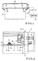
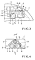
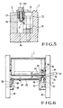
- Figs. 1 to 5 show a plate mounting apparatus for mounting a plate on a plate cylinder according to an embodiment of the present invention.
- a gap 2 is formed in the outer circumferential surface of a plate cylinder 1 over substantially the entire length thereof, and two open ends of the gap 2 are closed with disk-like bearers 3.
- a leading-side plate lockup device 4 and a trailing-side plate lockup device (not shown) having almost the same structure as that of the leading-side plate lockup device 4 are disposed in the gap 2 to extend parallel to each other over almost the entire length of the gap 2.
- the leading-side plate lockup device 4 has a plate lockup table 5 having a substantially rectangular section and extending in the axial direction of the gap 2.
- the plate lockup table 5 is positioned by a gauge plate 6 and fixed on the bottom surface of the gap 2 by bolts (not shown).
- a plurality of gripper plates 8 having substantially the same total length as that of the plate lockup table 5 and divided in the axial direction are swingably supported on the plate lockup table 5 by bolts (not shown).
- a cam shaft 11 having a plurality of cams each consisting of an arcuated portion 11a and a linear portion 11b is pivotally, axially supported, between a plate 10 pressed by a press plate 9 fixed on the end faces of the gripper plates 8 and a recess hole 5a of the plate lockup table 5, by the two bearers 3 and an intermediate bearing (not shown).
- a projecting portion 11 c of the cam shaft 11 projecting from a bearer 3 and having an intermediate portion coupled through coupling has a hexagonal section, so that the projecting portion 11c can be engaged by a wrench to turn the cam shaft 11.
- the gripper plates 8 having gripper surfaces 8a are biased in the opening direction toward a gripper surface 5b of the plate lockup table 5 by the spring force of a spring member (not shown).
- the gripper plates 8 are swung by the cooperation of the pivoting operation of the cam shaft 11 and the spring force of the spring member, and the gripper surfaces 8a are opened away from the gripper surface 5b.
- U-shaped reference pin holes 13a and 13b are formed in the leading end of a plate 13 spaced apart from each other by a predetermined distance. Plate making is performed with reference to these reference pin holes 13a and 13b.
- two pairs of triangular notches 5c and 8b are formed in the plate lockup table 5 and the corresponding gripper plates 8 at positions close to the end portions thereof in the longitudinal direction, so that the notches 5c and 8b correspond to the reference pin holes 13a and 13b.
- a reference pin base 14 having a triangular shape when seen from above and an inverted L-shaped section, is housed in each pair of notches 5c and 8b, and is fixed on the bottom surface of the gap 2 by a bolt 15.
- Two reference pins 16 are inserted in pin holes 14a of the reference pin base 14 and fixed by nuts 18. The distance between the two reference pins 16 is set to be equal to the distance between the reference pin holes 13a and 13b formed in the plate 13.
- the reference pins 16 are engaged with the corresponding reference pin holes 13a and 13b of the plate 13 inserted between the gripper surfaces 5b and 8a.
- wires 21 and 22 connected to a power supply 20 are connected to the two reference pins 16 serving as the detecting portions, and the reference pins 16 are rendered conductive by an insertion end 13c of the conductive plate 13 inserted between the gripper surfaces 5b and 8a. More specifically, when the bottom portions of the reference pin holes 13a and 13b of the plate 13 contact the reference pins 16 to be electrically connected to them, the two reference pins 16 serving as the detecting portions are rendered conductive through the insertion end 13c of the plate 13.
- a lamp 23 serving as an indicator is provided to the stationary portion of the machine frame. The lamp 23 is turned on when the two reference pins 16 are rendered conductive through the insertion end 13c of the plate 13.
- the two reference pins 16 serving as the detecting portions of the plate cylinder 1 are rendered conductive by the insertion end 13c of the conductive plate 13.
- the two reference pins 16 serving as the detecting portions and the lamp 23 serving as the indicator form a loop to turn on the lamp 23, so that the operator can confirm that the plate 13 is reliably inserted.
- the cam shaft 11 is turned to cause the arcuated portions 11a of the cams to contact the plate 10.
- the gripper surfaces 5b and 8a are closed against the spring force of the spring member to grip one end of the plate 13.
- the plate cylinder 1 is rotated by almost one revolution to wind the plate 13 on the circumferential surface of the plate cylinder 1.
- the trailing-side plate lockup device is caused to grip the other end of the plate 13 in the same manner as described above, and the trailing-side plate lockup device is moved in the circumferential direction of the plate cylinder 1, so that the plate 13 is tightened and brought into tight contact with the circumferential surface of the plate cylinder 1, thus completing mounting of the plate 13.
- the lamp 23 indicates whether the plate 13 is reliably inserted between the gripper surfaces 5b and 8a of the leading-side plate lockup device 4. Therefore, the plate 13 can be reliably gripped.
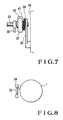
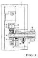
- Figs. 6 to 12 show a plate mounting apparatus for mounting a plate on a plate cylinder according to another embodiment of the present invention.
- the same members as those of the apparatus shown in Figs. 1 to 5 are denoted by the same reference numerals, and a detailed description thereof will be omitted.
- a leading-side plate lockup device 4 and a trailing-side plate lockup device are disposed in a gap 2 of a plate cylinder 1 axially supported by frames 30. After one end of a plate 13 is gripped by the plate lockup table 5, the plate cylinder 1 is rotated to wind the plate 13 on its circumferential surface, and the other end of the plate 13 is gripped by the trailing-side plate lockup device. The plate 13 is mounted on the plate cylinder 1 in this manner.
- roller arms 32 are pivotally mounted on the right and left frames 30, and a plurality of guide rollers 34 are axially mounted on a roller shaft 33 having two ends rotatably axially supported by the free end portions of the roller arms 32.
- Air cylinders 35 are pivotally mounted on the right and left frames 30, and the operating ends of piston rods 36 of the air cylinders 35 are pivotally coupled to the roller shaft 33.
- a contact lever 37 is pivotally supported on one end of the roller shaft 33 by interposing a torsion coil spring 38 between the contact lever 37 and the roller arms 32.
- contact rollers 41 and 42 corresponding to contacts 39 and 40 provided to the plate cylinder 1 are pivotally mounted on the free end of the contact lever 37.
- the contacts 39 and 40 are located at predetermined positions on the end face of the plate cylinder 1 so that they contact the contact rollers 41 and 42 only when the plate cylinder 1 is kept stopped in the plate gripping operation.
- wires 43 and 44 connected to the contacts 39 and 40 are connected to the two reference pins 16 in the same manner as in Fig. 1.
- the contact rollers 41 and 42 are connected to the power supply 20 and the lamp 23 serving as the indicator through wires 45 and 46. When the contacts 39 and 40 are brought into tight contact with the contact rollers 41 and 42, they are connected to the power supply 20.
- the contact 39 and the contact roller 41, and the contact 40 and the contact roller 42 are rendered conductive.
- the two reference pins 16 have been rendered conductive by the plate 13, a loop is formed by the reference pins 16 serving as the detecting portions and the lamp 23 serving as the indicator, and the lamp 23 is turned on.
- the cam shaft 11 is turned to cause the arcuated portions 11a of the cams to contact the plate 10.
- the gripper surfaces 5b and 8a are closed against the spring force of the spring member to grip one end of the plate 13.
- the plate cylinder 1 is rotated by almost one revolution to wind the plate 13 on the circumferential surface of the plate cylinder 1.
- the trailing-side plate lockup device is caused to grip the other end of the plate 13 in the same manner as described above, and the trailing-side plate lockup device is moved in the circumferential direction of the plate cylinder 1, so that the plate 13 is tightened and brought into tight contact with the circumferential surface of the plate cylinder 1, thus completing mounting of the plate 13.
- the reference pins 16 are used also as the electrodes. However, electrodes may be provided independently of the reference pins. If, however, the reference pins are used also as the electrodes, the number of components is decreased.
- the plate mounting apparatus for mounting a plate on the plate cylinder, detecting portions, which are rendered conductive by the insertion end of a plate inserted between the gripper surfaces of the gripper plates and the gripper surface of the plate lockup table, and an indicator indicating that the detecting portions are rendered conductive are provided. Therefore, during the mounting operation of the plate on the plate cylinder, the indicator, e.g., a lamp or a buzzer, informs that the plate is completely inserted between the gripper surfaces of the gripper plates and the gripper surface of the plate lockup table. Insertion becomes reliable as compared to conventional insertion which is left to the discretion of the operator, and variations caused by differing degrees of skill of the operators are eliminated, thereby improving the quality of the printed matter.
- the indicator e.g., a lamp or a buzzer
- the detecting portions are provided to the plate cylinder which is a rotary member
- the indicator is provided to the stationary portion of the machine frame
- contacts are provided to render the detecting portions and the indicators conductive when the plate cylinder is stopped. Therefore, since the contacts for closing the electrical circuit are not dosed during rotation of the plate cylinder, but are closed when the plate cylinder is kept stopped, the durability of the components forming the contact portions is improved. In addition, the problem of wiring between the plate cylinder as the rotary member and the indicator can be solved.
Landscapes
- Supply, Installation And Extraction Of Printed Sheets Or Plates (AREA)
- Unwinding Webs (AREA)
- Rolls And Other Rotary Bodies (AREA)
- Inking, Control Or Cleaning Of Printing Machines (AREA)
- Manufacture Or Reproduction Of Printing Formes (AREA)
Claims (3)
- Appareil pour le montage d'une plaque sur un cylindre porte-plaque comprenant :ledit appareil étant caractérisé en ce que :un dispositif (4) de verrouillage de plaque prévu à l'intérieur d'un intervalle (2) formé dans la surface circonférentielle dudit cylindre porte-plaque (1) de telle sorte qu'il ne s'étend pas au-delà de la surface circonférentielle dudit cylindre porte-plaque (1) et comportant des surfaces de saisie (5b, 8a) entre lesquelles est maintenue fermement ladite plaque (13) montée sur ledit cylindre porte-plaque (1),des moyens de détection qui comprennent une paire de goupilles de référence (16) disposées sur ledit dispositif (4) de verrouillage de plaque à l'intérieur dudit intervalle (2) de telle sorte qu'elles ne s'étendent pas au-delà de la surface circonférentielle dudit cylindre porte-plaque (1), lesdites goupilles de référence (16) étant susceptibles de venir s'engager avec au moins une encoche (13a, 13b) prévue dans une extrémité d'insertion (13c) de ladite plaque (13) et de former un contact électrique à ce niveau, etdes moyens indicateurs (23) pour confirmer et indiquer si une plaque introduite dans le dispositif de verrouillage de plaque est correctement positionnée,lesdites goupilles de référence (16) sont adaptées de façon à s'engager dans une paire d'encoches (13a, 13b) prévues dans ladite extrémité d'insertion (13c) de ladite plaque (13), grâce à quoi, lors de l'introduction de ladite plaque dans ledit dispositif de verrouillage de plaque, chacune desdites goupilles de référence (16) vient buter contre la base d'une encoche (13a, 13b), respectivement, et forme un contact électrique avec elle.lesdits moyens indicateurs (23) sont prévus sur une partie fixe dudit appareilun organe de guidage (34) est supporté sur un organe de support sur le cadre de la machine pour guider la plaque en direction de la surface de saisie dudit dispositif (4) de verrouillage de plaque lorsque la plaque est introduite, etdes moyens de connexion (39 à 42) sont prévus pour relier ladite paire de goupilles de référence (16) et lesdits moyens indicateurs (23) lorsque ledit cylindre porte-plaque (1) s'arrête dans une position prédéterminée de façon à permettre l'introduction de ladite extrémité (13c) d'introduction de la plaque dans ledit dispositif (4) de verrouillage de plaque, lesdits moyens de connexion comprenant une paire de contacts (39,40) formés sur ledit cylindre porte-plaque et une paire de galets de contact (41,42) prévus sur ledit organe support et susceptibles d'être amenés en contact étroit avec les contacts sur ledit cylindre porte-plaque en synchronisme avec une opération dudit organe de guidage lorsque la plaque est introduite à l'intérieur dudit dispositif de verrouillage de plaque.
- Appareil selon la revendication 1, dans lequel ladite paire de goupilles de référence sont respectivement fixées sur des embases (14) de goupilles de référence prévues dans l'intervalle dudit cylindre porte-plaque.
- Appareil selon la revendication 1, dans lequel ladite paire de goupilles de référence sont électriquement reliées l'une à l'autre par l'extrémité d'insertion de la plaque (13c) lorsque lesdites goupilles de référence (16) viennent s'engager avec les encoches (13a, 13b) de ladite plaque (13).
Applications Claiming Priority (3)
| Application Number | Priority Date | Filing Date | Title |
|---|---|---|---|
| JP2599392 | 1992-01-17 | ||
| JP02599392A JP3194199B2 (ja) | 1992-01-17 | 1992-01-17 | 版胴への刷版装着装置 |
| JP25993/92 | 1992-01-17 |
Publications (3)
| Publication Number | Publication Date |
|---|---|
| EP0551976A1 EP0551976A1 (fr) | 1993-07-21 |
| EP0551976B1 EP0551976B1 (fr) | 1996-07-03 |
| EP0551976B2 true EP0551976B2 (fr) | 2002-10-16 |
Family
ID=12181244
Family Applications (1)
| Application Number | Title | Priority Date | Filing Date |
|---|---|---|---|
| EP93250013A Expired - Lifetime EP0551976B2 (fr) | 1992-01-17 | 1993-01-14 | Dispositif pour monter une plaque sur un cylindre porte-plaque |
Country Status (5)
| Country | Link |
|---|---|
| US (1) | US5383402A (fr) |
| EP (1) | EP0551976B2 (fr) |
| JP (1) | JP3194199B2 (fr) |
| AT (1) | ATE139936T1 (fr) |
| DE (1) | DE69303380T3 (fr) |
Families Citing this family (33)
| Publication number | Priority date | Publication date | Assignee | Title |
|---|---|---|---|---|
| JP3379974B2 (ja) | 1992-02-10 | 2003-02-24 | 株式会社小森コーポレーション | 刷版装着状況確認装置 |
| DE4223908C2 (de) * | 1992-06-30 | 1995-09-28 | Lehner Gmbh | Spannvorrichtung zum Spannen und Verstellen einer Druckplatte auf einem Plattenzylinder |
| JP2573523Y2 (ja) * | 1992-07-31 | 1998-06-04 | 株式会社小森コーポレーション | 印刷機の刷版装着装置 |
| DE4226780C2 (de) * | 1992-08-13 | 1994-12-01 | Roland Man Druckmasch | Vorrichtung zur Kontrolle der registergerechten Anlage einer Druckplatte auf dem Plattenzylinder von Druckmaschinen, insbesondere Bogenoffsetdruckmaschinen |
| EP0660776B1 (fr) * | 1992-09-18 | 1996-12-27 | KOENIG & BAUER-ALBERT AKTIENGESELLSCHAFT | Procede visant a amener des plaques d'impression |
| DE4338664C2 (de) * | 1993-11-12 | 1995-09-14 | Roland Man Druckmasch | Verfahren und Vorrichtung zum Steuern eines automatisierten Druckplattenwechselvorganges bei Druckmaschinen |
| DE4340052C2 (de) * | 1993-11-24 | 1996-06-13 | Roland Man Druckmasch | Vorrichtung zur Kontrolle der registergerechten Anlage einer Druckplatte auf einem Plattenzylinder einer Druckmaschine |
| DE4439623C2 (de) * | 1994-11-05 | 1999-01-14 | Roland Man Druckmasch | Verfahren zum automatischen Zuführen von Druckplatten |
| DE9418049U1 (de) * | 1994-11-11 | 1994-12-22 | MAN Roland Druckmaschinen AG, 63075 Offenbach | Vorrichtung für das registergerechte Anlegen von Druckplatten |
| EP0739728B1 (fr) * | 1995-04-26 | 1999-02-10 | Heidelberger Druckmaschinen Aktiengesellschaft | Procédé et dispositif pour fixer un cliché sur un cylindre |
| DE19620997C2 (de) * | 1996-05-24 | 1998-03-26 | Koenig & Bauer Albert Ag | Verfahren und Vorrichtung zum axialen Positionieren einer Druckplatte |
| US6113346A (en) | 1996-07-31 | 2000-09-05 | Agfa Corporation | Method for loading and unloading a supply of plates in an automated plate handler |
| DE29701585U1 (de) * | 1997-01-31 | 1997-03-13 | MAN Roland Druckmaschinen AG, 63075 Offenbach | Druckplatte |
| DE19854845B4 (de) * | 1998-01-30 | 2011-02-24 | Heidelberger Druckmaschinen Ag | Verfahren und Vorrichtung zur automatischen Erfassung von mindestens einer Druckplattenkante |
| DE19803723A1 (de) * | 1998-01-30 | 1999-08-05 | Heidelberger Druckmasch Ag | Verfahren und Vorrichtung zur registergenauen Vorpositionierung einer Druckplatte |
| DE19803725A1 (de) * | 1998-01-30 | 1999-08-05 | Heidelberger Druckmasch Ag | Vorrichtung zur registergenauen Positionierung einer Druckplatte |
| DE29808098U1 (de) * | 1998-05-06 | 1998-07-16 | MAN Roland Druckmaschinen AG, 63075 Offenbach | Einrichtung zur Registerkontrolle |
| DE19839149C1 (de) * | 1998-08-28 | 2000-01-20 | Roland Man Druckmasch | Vorrichtung zur registergerechten Plattenanlage |
| DE29815444U1 (de) * | 1998-08-28 | 1998-11-26 | MAN Roland Druckmaschinen AG, 63075 Offenbach | Stromversorgung für einen Druckmaschinenzylinder |
| DE29815443U1 (de) | 1998-08-28 | 1998-11-26 | MAN Roland Druckmaschinen AG, 63075 Offenbach | Einrichtung zur Registerkontrolle |
| US6125757A (en) * | 1998-10-19 | 2000-10-03 | Heidelberger Druckmaschinen Ag | Method and apparatus for performing a flying printing plate change |
| DE19957920A1 (de) | 1998-12-23 | 2000-06-29 | Heidelberger Druckmasch Ag | APW-Induktive Plattenkontrolle |
| DE10007819A1 (de) | 1999-03-10 | 2000-09-14 | Heidelberger Druckmasch Ag | Registerbolzen-Taster Vorrichtung zur Erfassung einer Druckplattenlage |
| DE29907122U1 (de) * | 1999-04-22 | 1999-07-01 | MAN Roland Druckmaschinen AG, 63075 Offenbach | Einrichtung zur Kontrolle der Lage von Druckplatten auf den Plattenzylinder von Druckmaschinen |
| DE29907120U1 (de) * | 1999-04-22 | 1999-07-01 | MAN Roland Druckmaschinen AG, 63075 Offenbach | Einrichtung zur Kontrolle der registergerechten Anlage von Druckplatten |
| US6691616B2 (en) | 1999-05-07 | 2004-02-17 | Heidelberger Druckmaschinen Ag | Device for detecting the position of a printing plate on a cylinder of a rotary printing machine |
| DE19921272A1 (de) * | 1999-05-07 | 2000-11-09 | Heidelberger Druckmasch Ag | Piezokeramische Einspannüberwachung Vorrichtung zur Erfassung einer Druckplattenlage |
| ES2259588T3 (es) * | 1999-09-14 | 2006-10-16 | Komori Corporation | Aparato de introduccion de plancha en una prensa rotativa de imprimir. |
| US6460457B1 (en) * | 1999-11-22 | 2002-10-08 | Heidelberger Druckmaschinen Ag | Method and device for automatically providing a printing plate to a plate cylinder |
| US6318262B1 (en) * | 2000-02-25 | 2001-11-20 | Agfa Corporation | External drum imaging system |
| US6510793B1 (en) * | 2001-06-28 | 2003-01-28 | Eastman Kodak Company | Imaging apparatus and printing plate mounting surface for use in an imaging apparatus having printing plate registration detection |
| US6739250B2 (en) * | 2002-03-20 | 2004-05-25 | Fuji Photo Film Co., Ltd. | Device for controlling rotation of rotating drum |
| DE102006048676B4 (de) * | 2006-10-14 | 2011-07-07 | KOENIG & BAUER Aktiengesellschaft, 97080 | Einrichtung zum Erkennen eines Vorhandenseins eines Aufzugs auf einem Zylinder |
Family Cites Families (7)
| Publication number | Priority date | Publication date | Assignee | Title |
|---|---|---|---|---|
| GB1321562A (en) * | 1971-06-15 | 1973-06-27 | Teledictor Ltd | Conductive sheet detection apparatus |
| DE3000576A1 (de) * | 1980-01-09 | 1981-07-16 | Grapho-Metronic Meß- und Regeltechnik GmbH & Co, KG, 8000 München | Registersystem fuer druckmaschinen |
| DE3138865C2 (de) * | 1981-09-30 | 1983-12-29 | Grapho Metronic Meß- und Regeltechnik GmbH & Co KG, 8000 München | Vorrichtung zur Kontrolle des registergenauen Aufspannens von Druckplatten auf dem Plattenzylinder einer Offset-Druckmaschine |
| DE3325583C2 (de) * | 1983-07-15 | 1991-12-12 | Heinz 5653 Leichlingen Metje | Anschlagsystem für Druckplatten, insbesondere für Druckplattenstanzen |
| DE3438931A1 (de) * | 1984-10-24 | 1986-04-24 | Heidelberger Druckmaschinen Ag, 6900 Heidelberg | Vorrichtung zum passerhaltigen ausrichten einer biegsamen druckplatte auf dem plattenzylinder von rotationsdruckmaschinen |
| IT1183507B (it) * | 1985-03-28 | 1987-10-22 | Arnoldo Mandadori Editore Offi | Dispositivo di messa a registro delle lastre da stampa sui cilindri di macchine da stampa offset piane |
| DE3638428C1 (en) * | 1986-11-11 | 1988-06-01 | 2 B Praez Stechnik Gmbh Fuer D | Processing device with in-register positioning for offset printing formes |
-
1992
- 1992-01-17 JP JP02599392A patent/JP3194199B2/ja not_active Expired - Fee Related
-
1993
- 1993-01-14 DE DE69303380T patent/DE69303380T3/de not_active Expired - Fee Related
- 1993-01-14 AT AT93250013T patent/ATE139936T1/de not_active IP Right Cessation
- 1993-01-14 EP EP93250013A patent/EP0551976B2/fr not_active Expired - Lifetime
-
1994
- 1994-03-10 US US08/209,607 patent/US5383402A/en not_active Expired - Lifetime
Also Published As
| Publication number | Publication date |
|---|---|
| EP0551976A1 (fr) | 1993-07-21 |
| DE69303380D1 (de) | 1996-08-08 |
| EP0551976B1 (fr) | 1996-07-03 |
| US5383402A (en) | 1995-01-24 |
| ATE139936T1 (de) | 1996-07-15 |
| JP3194199B2 (ja) | 2001-07-30 |
| JPH05193114A (ja) | 1993-08-03 |
| DE69303380T2 (de) | 1997-02-06 |
| DE69303380T3 (de) | 2003-06-12 |
Similar Documents
| Publication | Publication Date | Title |
|---|---|---|
| EP0551976B2 (fr) | Dispositif pour monter une plaque sur un cylindre porte-plaque | |
| EP0581212B2 (fr) | Appareil de montage d'une plaque pour presse à imprimer | |
| JP3379974B2 (ja) | 刷版装着状況確認装置 | |
| EP0582903B1 (fr) | Dispositif de contrÔle du positionnement repéré d'une plaque d'impression sur un cylindre de plaque d'une machine à imprimer, en particulier d'une machine offset d'impression de feuilles | |
| AU3663889A (en) | Combined sheet-fed rotary printing machine for securities, especially banknotes | |
| US4596186A (en) | Mechanism for correcting the twist of a plate on a printer | |
| US5746132A (en) | Variable repeat plate and blanket cylinder mechanism | |
| JP4186028B2 (ja) | 検査輪転印刷機 | |
| JP3294363B2 (ja) | 紙幣の品質を検査する装置における印刷シートを搬送する装置 | |
| US6241241B1 (en) | Method and device for eliminating rhythmic register errors in sheet-fed rotary printing machines | |
| JPH11262997A (ja) | 刷版を正確な見当で位置決めする装置 | |
| JP2929521B2 (ja) | 印刷機械の版胴に版板を供給する装置 | |
| JP3375601B2 (ja) | 組版交換方法および装置 | |
| US4833988A (en) | Inking device for printing apparatus | |
| US4759286A (en) | Mounting bracket for printing or duplicating machine roller | |
| GB2123345A (en) | Offset press having two printing units | |
| JP3933801B2 (ja) | 版交換装置 | |
| US4864928A (en) | Printing machine for printing continuous slip | |
| CA1144816A (fr) | Conversion de la typographie a la lithographie offset | |
| EP0635367B1 (fr) | Dispositif de positionnement de clichés sur le cylindre porte-plaque d'une machine d'impression | |
| US4526364A (en) | Sheet feeding mechanism for duplicating machine with duplexing capability | |
| JPH0349880Y2 (fr) | ||
| JPH09300588A (ja) | 輪転機のブランケット装着方法および装着装置 | |
| JP3220909B2 (ja) | 輪転印刷機の版押え装置。 | |
| DE29808098U1 (de) | Einrichtung zur Registerkontrolle |
Legal Events
| Date | Code | Title | Description |
|---|---|---|---|
| PUAI | Public reference made under article 153(3) epc to a published international application that has entered the european phase |
Free format text: ORIGINAL CODE: 0009012 |
|
| 17P | Request for examination filed |
Effective date: 19930205 |
|
| AK | Designated contracting states |
Kind code of ref document: A1 Designated state(s): AT CH DE FR GB IT LI NL SE |
|
| 17Q | First examination report despatched |
Effective date: 19940128 |
|
| GRAH | Despatch of communication of intention to grant a patent |
Free format text: ORIGINAL CODE: EPIDOS IGRA |
|
| GRAA | (expected) grant |
Free format text: ORIGINAL CODE: 0009210 |
|
| AK | Designated contracting states |
Kind code of ref document: B1 Designated state(s): AT CH DE FR GB IT LI NL SE |
|
| REF | Corresponds to: |
Ref document number: 139936 Country of ref document: AT Date of ref document: 19960715 Kind code of ref document: T |
|
| REF | Corresponds to: |
Ref document number: 69303380 Country of ref document: DE Date of ref document: 19960808 |
|
| ET | Fr: translation filed | ||
| ITF | It: translation for a ep patent filed | ||
| REG | Reference to a national code |
Ref country code: CH Ref legal event code: NV Representative=s name: PATENTANWALTSBUREAU BOSSHARD UND LUCHS |
|
| PLBI | Opposition filed |
Free format text: ORIGINAL CODE: 0009260 |
|
| PLBI | Opposition filed |
Free format text: ORIGINAL CODE: 0009260 |
|
| 26 | Opposition filed |
Opponent name: MAN ROLAND DRUCKMASCHINEN AG Effective date: 19970306 |
|
| PLBF | Reply of patent proprietor to notice(s) of opposition |
Free format text: ORIGINAL CODE: EPIDOS OBSO |
|
| 26 | Opposition filed |
Opponent name: HEIDELBERGER DRUCKMASCHINEN AG Effective date: 19970329 Opponent name: MAN ROLAND DRUCKMASCHINEN AG Effective date: 19970306 |
|
| NLR1 | Nl: opposition has been filed with the epo |
Opponent name: MAN ROLAND DRUCKMASCHINEN AG |
|
| NLR1 | Nl: opposition has been filed with the epo |
Opponent name: HEIDELBERGER DRUCKMASCHINEN AG Opponent name: MAN ROLAND DRUCKMASCHINEN AG |
|
| PLBF | Reply of patent proprietor to notice(s) of opposition |
Free format text: ORIGINAL CODE: EPIDOS OBSO |
|
| PLAW | Interlocutory decision in opposition |
Free format text: ORIGINAL CODE: EPIDOS IDOP |
|
| APAC | Appeal dossier modified |
Free format text: ORIGINAL CODE: EPIDOS NOAPO |
|
| APAE | Appeal reference modified |
Free format text: ORIGINAL CODE: EPIDOS REFNO |
|
| APAC | Appeal dossier modified |
Free format text: ORIGINAL CODE: EPIDOS NOAPO |
|
| APAC | Appeal dossier modified |
Free format text: ORIGINAL CODE: EPIDOS NOAPO |
|
| REG | Reference to a national code |
Ref country code: GB Ref legal event code: IF02 |
|
| PLAW | Interlocutory decision in opposition |
Free format text: ORIGINAL CODE: EPIDOS IDOP |
|
| PUAH | Patent maintained in amended form |
Free format text: ORIGINAL CODE: 0009272 |
|
| 27A | Patent maintained in amended form |
Effective date: 20021016 |
|
| AK | Designated contracting states |
Kind code of ref document: B2 Designated state(s): AT CH DE FR GB IT LI NL SE |
|
| REG | Reference to a national code |
Ref country code: CH Ref legal event code: AEN Free format text: AUFRECHTERHALTUNG DES PATENTES IN GEAENDERTER FORM |
|
| NLR2 | Nl: decision of opposition | ||
| NLR3 | Nl: receipt of modified translations in the netherlands language after an opposition procedure | ||
| ET3 | Fr: translation filed ** decision concerning opposition | ||
| APAH | Appeal reference modified |
Free format text: ORIGINAL CODE: EPIDOSCREFNO |
|
| PGFP | Annual fee paid to national office [announced via postgrant information from national office to epo] |
Ref country code: AT Payment date: 20090113 Year of fee payment: 17 |
|
| PGFP | Annual fee paid to national office [announced via postgrant information from national office to epo] |
Ref country code: NL Payment date: 20090115 Year of fee payment: 17 Ref country code: DE Payment date: 20090108 Year of fee payment: 17 |
|
| PGFP | Annual fee paid to national office [announced via postgrant information from national office to epo] |
Ref country code: GB Payment date: 20090114 Year of fee payment: 17 Ref country code: CH Payment date: 20090114 Year of fee payment: 17 |
|
| PGFP | Annual fee paid to national office [announced via postgrant information from national office to epo] |
Ref country code: SE Payment date: 20090108 Year of fee payment: 17 Ref country code: IT Payment date: 20090127 Year of fee payment: 17 |
|
| PGFP | Annual fee paid to national office [announced via postgrant information from national office to epo] |
Ref country code: FR Payment date: 20090113 Year of fee payment: 17 |
|
| REG | Reference to a national code |
Ref country code: NL Ref legal event code: V1 Effective date: 20100801 |
|
| REG | Reference to a national code |
Ref country code: CH Ref legal event code: PL |
|
| GBPC | Gb: european patent ceased through non-payment of renewal fee |
Effective date: 20100114 |
|
| EUG | Se: european patent has lapsed | ||
| REG | Reference to a national code |
Ref country code: FR Ref legal event code: ST Effective date: 20100930 |
|
| PG25 | Lapsed in a contracting state [announced via postgrant information from national office to epo] |
Ref country code: NL Free format text: LAPSE BECAUSE OF NON-PAYMENT OF DUE FEES Effective date: 20100801 Ref country code: LI Free format text: LAPSE BECAUSE OF NON-PAYMENT OF DUE FEES Effective date: 20100131 Ref country code: FR Free format text: LAPSE BECAUSE OF NON-PAYMENT OF DUE FEES Effective date: 20100201 Ref country code: CH Free format text: LAPSE BECAUSE OF NON-PAYMENT OF DUE FEES Effective date: 20100131 |
|
| PG25 | Lapsed in a contracting state [announced via postgrant information from national office to epo] |
Ref country code: DE Free format text: LAPSE BECAUSE OF NON-PAYMENT OF DUE FEES Effective date: 20100803 Ref country code: AT Free format text: LAPSE BECAUSE OF NON-PAYMENT OF DUE FEES Effective date: 20100114 |
|
| PG25 | Lapsed in a contracting state [announced via postgrant information from national office to epo] |
Ref country code: GB Free format text: LAPSE BECAUSE OF NON-PAYMENT OF DUE FEES Effective date: 20100114 |
|
| PG25 | Lapsed in a contracting state [announced via postgrant information from national office to epo] |
Ref country code: IT Free format text: LAPSE BECAUSE OF NON-PAYMENT OF DUE FEES Effective date: 20100114 |
|
| PG25 | Lapsed in a contracting state [announced via postgrant information from national office to epo] |
Ref country code: SE Free format text: LAPSE BECAUSE OF NON-PAYMENT OF DUE FEES Effective date: 20100115 |