EP0551987A1 - Assemblage chauffant pour fils - Google Patents
Assemblage chauffant pour fils Download PDFInfo
- Publication number
- EP0551987A1 EP0551987A1 EP93300085A EP93300085A EP0551987A1 EP 0551987 A1 EP0551987 A1 EP 0551987A1 EP 93300085 A EP93300085 A EP 93300085A EP 93300085 A EP93300085 A EP 93300085A EP 0551987 A1 EP0551987 A1 EP 0551987A1
- Authority
- EP
- European Patent Office
- Prior art keywords
- yarn
- heating assembly
- slot
- bore
- assembly according
- Prior art date
- Legal status (The legal status is an assumption and is not a legal conclusion. Google has not performed a legal analysis and makes no representation as to the accuracy of the status listed.)
- Withdrawn
Links
Images


Classifications
-
- D—TEXTILES; PAPER
- D02—YARNS; MECHANICAL FINISHING OF YARNS OR ROPES; WARPING OR BEAMING
- D02J—FINISHING OR DRESSING OF FILAMENTS, YARNS, THREADS, CORDS, ROPES OR THE LIKE
- D02J13/00—Heating or cooling the yarn, thread, cord, rope, or the like, not specific to any one of the processes provided for in this subclass
- D02J13/001—Heating or cooling the yarn, thread, cord, rope, or the like, not specific to any one of the processes provided for in this subclass in a tube or vessel
-
- D—TEXTILES; PAPER
- D02—YARNS; MECHANICAL FINISHING OF YARNS OR ROPES; WARPING OR BEAMING
- D02J—FINISHING OR DRESSING OF FILAMENTS, YARNS, THREADS, CORDS, ROPES OR THE LIKE
- D02J13/00—Heating or cooling the yarn, thread, cord, rope, or the like, not specific to any one of the processes provided for in this subclass
Definitions
- This invention relates to yarn heating assemblies, and in particular to assemblies for heating a yarn during the false twisting stage of a yarn false twist texturing process.
- a heating assembly is described in British patent application No. 2250340, the heating assembly in that case comprising an elongate heated surface and yarn guide means disposed relative to each other in operation to provide a yarn path which extends adjacent the heated surface.
- the various embodiments of heater described in that application comprise a plurality of yarn guides disposed along a door of the heater to guide the yarn along the desired yarn path adjacent the heated surface when the door is in its closed, operational position.
- the plurality of yarn guides facilitate the provision of a curved yarn path adjacent a curved heated surface and/or the adjustment of the disposition of at least a part of the yarn path relative to the heated surface.
- the plurality of yarn guides also provide good support for the running yarn within the heater to prevent instability at the required yarn throughput speeds.
- the invention provides a yarn heating assembly comprising an elongate heated body and having a groove extending therealong to provide a yarn path through the body, the groove comprising a bore which in cross-section substantially surrounds the yarn path and a slot communicating with the bore and the outer surface of the heating assembly, guides disposed adjacent the ends of the groove to guide a yarn along the yarn path adjacent the surface of the bore, a heating device adapted to heat the body, and at least one baffle disposed in operation at the groove to restrict the flow of air along the yarn path.
- the slot may have a width which, at least in the region thereof which communicates with the bore, is a predetermined width sufficient only to allow the threading of a yarn therethrough.
- the heating assembly may comprise a closing device disposed in operation substantially to close the slot, in which case the baffle may be integral with, or secured to, the closing device, and a plurality of baffles may be provided which project from the closing device and are mutually spaced longitudinally thereof.
- the baffle may comprise an elongate member secured to the closing device to extend longitudinally thereof, and may be spaced therefrom to provide an air gap therebetween.
- the baffle may be of a material having good heat reflecting properties, and the closing device may be of a material having good thermal insulating properties.
- the baffle may comprise a metal tube, and may be of stainless steel.
- the closing device may comprise a door which is pivotally mounted relative to the body so as to be movable between an open, threading position and a closed, operating position.
- the guides may be attached to the closing device so as to be movable therewith.
- the slot may have a width, at the region which communicates with the outer surface of the heating assembly, which is the predetermined width.
- a heating assembly 40 is mounted.
- the machine 28 illustrated is a false twist texturing machine for texturing a yarn 11 and, in addition to the heating assembly 40, comprises a cooling plate 25 mounted on the frame 29 of the machine 28, and a first feed device 24 mounted on a creel 22.
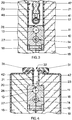
- the heating assembly 40 comprises an elongate heated body 10, which is formed in two halves secured to each other by screws 12, rivets or clips, and has extending therealong a groove 23 in the form of a bore 13 and a slot 20.
- the bore 13 defines a path for the yarn 11 to travel through the heating assembly 40, which yarn path is adjacent the surface of the bore 13 and is substantially surrounded thereby.
- the body 10 has the bore 13, a "neck" part 26 of the slot 20 which communicates with the bore 13, and a second bore 14 extending therealong.
- An electric heating element 27 extends along the second bore 14 to heat the body 10 to the required temperature, for example in the range 300 to 800 C.
- the yarn 11 is guided by guides 15, 16 at the inlet and outlet end respectively of the heater 40 to travel along the bore 13 to be heated by the body 10.
- the body 10 is enclosed substantially by a thermal insulating material 18 which is also in two halves within a casing 19, and is formed to have a slot 20 in which the body 10 is located.
- the sides of the slot 20 are lined with linings 21 of a rigid insulating material, e.g. fibre board, which serve to retain the body 10 in its location at the bottom of the slot 20.
- a cover 22 closes the casing 19 and secures the heater 40 to the frame of the machine 28.
- a closing device or door 43 substantially closes the neck part 26, substantially fills the slot 20 and closes the outer end of the slot 20 during operation of the machine 28, and is pivotally mounted at pivot 44 provided on a door mounting bracket 57.
- the door 43 may be moved between a closed, operating position shown in Fig. 2. and in full lines in Fig. 1, and an open, threading position shown in broken lines in Fig. 1.
- the yarn 11 travels from the creel 22 through the open nip of the first feed device 24, over a guide pin 46 on the door mounting arm 45 and then to the false twist device (not shown) without entering the heating body bore 13 or contacting the cooling plate 25.
- the door 43 comprises a closing plate 47 of a good thermal insulating material which is attached to the mounting arm 45, and which is of a thickness such that it will just enter the slot 20 in the cover 42, casing 19 and insulating material 18 substantially to close it.
- Projecting from the inner edge of the closing plate 47 are several posts 48 by means of which a baffle 17 is supported on the closing plate 47.
- the baffle 17 comprises a tube of heat reflecting material, such as stainless steel, which is of a diameter such that it almost closes the neck part 26 of the slot 20 and hence the bore 13 in the heated body 10.
- Clips 41 retain the baffle tube 17 on the posts 48 and spaced from the closing plate 47 so as to provide an air gap therebetween which reduces the transfer of heat from the baffle tube 17 to the closing plate 47.
- the baffle tube 17 also serves to reduce considerably the flow of air longitudinally of the heater 40 in the region of the bore 13, whether caused by convection or by entrainment by the yarn 11, and such airflow reduction has been found to increase the efficiency of heating the yarn 11 by an appreciable amount.
- the tube 17 may be closed at its ends to prevent airflow through it and consequential internal contamination.
- the posts 48 are of a size and shape such that at each post position the neck 26 opening of the slot 20 into the bore 13 is almost closed so as to form baffles 17 whereby airflow longitudinally of the bore 13 is restricted.
- the width of the neck part 26 is reduced, compared with that of Fig. 2, to a predetermined width sufficient only to allow threading of the yarn 11 therethrough, for example between 1.5 and 2.0mm.
- Figs. 1 and 2 also mounted on the closing plate 47, on opposed faces thereof, are two side members 49 which are joined to each other by slider pins 50 passing through slots 51 in the closing plate 47.
- a longitudinally extending lip 52 on one of the side members 49 is engaged by two cranked arms 53, each of which is pivotally mounted on the closing plate 47 at pivots 54, and is biassed by a spring 55 to push the side members 49 to a position in which they lie on opposed sides of the baffle tube 17 to shield it and protect it from damage when the door 43 is in the open, threading position.
- Yarn guides 15, 16 are mounted also on the door 43.
- a spigot 58 is provided on the door mounting arm 45, and is engageable in recesses in the rim of a locator plate 59 provided on the door mounting bracket 57 concentrically with the pivot 44.
- a heating assembly 30 comprising a heated body 10 of similar construction to that shown in Fig. 3.
- the body 10 is substantially surrounded by heat insulating material 18 housed in a casing 19 and cover 42 similar to that described in relation to the previous embodiments.
- a slot 20, having sides lined with linings 21 of fibreboard, communicates with bore 13 and the outside of the heating assembly 30.
- the door 43 is replaced by a different formation of slot 20.
- a capping 31 conveniently a pultrusion, secures the fibreboard slot linings 21 relative to the cover 42 and provides an opening 32 which, as with neck 26, is reduced also compared with the width of the slot 20 of this and the previous embodiments, to the predetermined width sufficient only to allow threading of the yarn 11 therethrough.
- the pultrusion cappings 31 reduce the transfer of heat by conduction from the fibreboard linings 21 to the cover 42, and the relatively small slot width at the neck 26 and opening 32 reduces heat loss by radiation or convection from the bore 13.
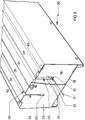
- the flow of air along the bore 13 or slot 20 is restricted in this embodiment by means of baffle plates 33 provided at each end of the heating assembly 30.
- the baffle plates 33 have a slot 34 of width similar to that of opening 32 and neck 26 aligned centrally with the slot 20, and an opening 35 aligned with the bore 13 and slightly enlarged compared with the slot 34 only to minimise the risk of contact between the yarn 11 and the baffle plate 33 due to ballooning or vibration during running.
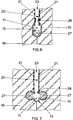
- FIGs. 6 and 7 there are shown two further embodiments which are similar to that described above and shown in Figs. 4 and 5, except that in these cases the block of brass forming the heated body 10 has been replaced by sheets of stainless steel formed to provide the bore 13 and to enclose one (see Fig. 6) or two (see Fig. 7) heating elements 27.
- Such assemblies are less costly than the previously described embodiment and reduce the mass of the heat sink whilst providing a high degree of heat reflection towards the yarn 11.
- the baffle 47 may be of a cross -section other than circular, and may be solid instead of tubular.
- individual baffles 48 may be provided and formed as yarn guides disposed in operation to be substantially equidistant from the longitudinally curved bottom of the groove 23.
- the cooling plate 25 may be curved upwardly and the yarn 11 run on the upper surface thereof as a means of reducing the angle of wrap of the yarn 11 around the guide 16 at the exit end of the heater 40 and entry of the cooling plate 25.
Landscapes
- Engineering & Computer Science (AREA)
- Textile Engineering (AREA)
- Yarns And Mechanical Finishing Of Yarns Or Ropes (AREA)
- Treatment Of Fiber Materials (AREA)
Applications Claiming Priority (2)
| Application Number | Priority Date | Filing Date | Title |
|---|---|---|---|
| GB929200842A GB9200842D0 (en) | 1992-01-15 | 1992-01-15 | Yarn heating arrangement |
| GB9200842 | 1992-01-15 |
Publications (1)
| Publication Number | Publication Date |
|---|---|
| EP0551987A1 true EP0551987A1 (fr) | 1993-07-21 |
Family
ID=10708652
Family Applications (1)
| Application Number | Title | Priority Date | Filing Date |
|---|---|---|---|
| EP93300085A Withdrawn EP0551987A1 (fr) | 1992-01-15 | 1993-01-07 | Assemblage chauffant pour fils |
Country Status (3)
| Country | Link |
|---|---|
| EP (1) | EP0551987A1 (fr) |
| JP (1) | JPH05339832A (fr) |
| GB (2) | GB9200842D0 (fr) |
Citations (3)
| Publication number | Priority date | Publication date | Assignee | Title |
|---|---|---|---|---|
| US2204603A (en) * | 1937-09-07 | 1940-06-18 | Ind Rayon Corp | Apparatus for drying thread or the like |
| US3015872A (en) * | 1957-04-25 | 1962-01-09 | British Nylon Spinners Ltd | Apparatus for the heat treatment of running yarns |
| EP0483989A1 (fr) * | 1990-10-27 | 1992-05-06 | Rieter-Scragg Limited | Système pour chauffer des fils |
Family Cites Families (2)
| Publication number | Priority date | Publication date | Assignee | Title |
|---|---|---|---|---|
| GB612197A (en) * | 1946-05-17 | 1948-11-09 | Johann Joseph Stoeckly | Improvements in or relating to a process and device for drying filaments |
| CH464433A (de) * | 1967-08-31 | 1968-10-31 | Heberlein & Co Ag | Vorrichtung zur Wärmebehandlung von kontinuierlich durchlaufenden fadenförmigen Gebilden, insbesondere Textilgarnen, mittels widerstandsbeheiztem Kontaktkörper |
-
1992
- 1992-01-15 GB GB929200842A patent/GB9200842D0/en active Pending
-
1993
- 1993-01-07 EP EP93300085A patent/EP0551987A1/fr not_active Withdrawn
- 1993-01-07 GB GB9300198A patent/GB2263333A/en not_active Withdrawn
- 1993-01-14 JP JP2211893A patent/JPH05339832A/ja active Pending
Patent Citations (3)
| Publication number | Priority date | Publication date | Assignee | Title |
|---|---|---|---|---|
| US2204603A (en) * | 1937-09-07 | 1940-06-18 | Ind Rayon Corp | Apparatus for drying thread or the like |
| US3015872A (en) * | 1957-04-25 | 1962-01-09 | British Nylon Spinners Ltd | Apparatus for the heat treatment of running yarns |
| EP0483989A1 (fr) * | 1990-10-27 | 1992-05-06 | Rieter-Scragg Limited | Système pour chauffer des fils |
Also Published As
| Publication number | Publication date |
|---|---|
| GB9300198D0 (en) | 1993-03-03 |
| GB9200842D0 (en) | 1992-03-11 |
| GB2263333A (en) | 1993-07-21 |
| JPH05339832A (ja) | 1993-12-21 |
Similar Documents
| Publication | Publication Date | Title |
|---|---|---|
| EP2574691B1 (fr) | Dispositif de chauffage pour fil | |
| GB2056508A (en) | Yarn heating apparatus for false twist yarn crimping machine | |
| EP0551987A1 (fr) | Assemblage chauffant pour fils | |
| TW445316B (en) | Cooling device for false twisting machine | |
| US20230417449A1 (en) | Air Cooling Mechanism, Air Guide Member and Heating Device | |
| EP0248769B1 (fr) | Dispositif de réglage de la température pour les machines et cylindres d'extrusion, d'injection et d'étirage de matière plastique | |
| EP0483989A1 (fr) | Système pour chauffer des fils | |
| GB2273302A (en) | Heating means for false-twister | |
| EP0853150B1 (fr) | Procédé de texturation d'un fil | |
| US4513514A (en) | Apparatus and method for the heat treatment of yarn | |
| EP0237991B1 (fr) | Dispositif de guidage de carte | |
| US7149416B2 (en) | Clothes dryer heater with air flow increasing device adjacent the heating element | |
| US5628175A (en) | Heating apparatus for heating an advancing synthetic filament yarn | |
| US4255134A (en) | Yarn heating apparatus | |
| CN223532999U (zh) | 一种热缩管烘烤装置 | |
| JPS6142937Y2 (fr) | ||
| JPH11131332A (ja) | 繊維機械配置 | |
| US3159735A (en) | Fixing unit for photocopy machines | |
| TW202342840A (zh) | 加熱裝置 | |
| US4300341A (en) | Housing for holding a control device with heat-generating elements for a thread monitor of an open-end spinning station | |
| JP2571185B2 (ja) | 仮撚り加工用加熱装置 | |
| JP2000305386A (ja) | 定着装置 | |
| JPH09279435A (ja) | 仮撚機の冷却プレート | |
| JP2003113542A (ja) | 仮撚加工機 | |
| EP0994206A1 (fr) | Dispositif de chauffage pour fils |
Legal Events
| Date | Code | Title | Description |
|---|---|---|---|
| PUAI | Public reference made under article 153(3) epc to a published international application that has entered the european phase |
Free format text: ORIGINAL CODE: 0009012 |
|
| AK | Designated contracting states |
Kind code of ref document: A1 Designated state(s): CH DE FR IT LI |
|
| RAP1 | Party data changed (applicant data changed or rights of an application transferred) |
Owner name: RIETER SCRAGG LIMITED |
|
| 18D | Application deemed to be withdrawn |
Effective date: 19940122 |