EP0552906A2 - Abtauanlassverfahren und -vorrichtung für Kältemittelverdampfer - Google Patents
Abtauanlassverfahren und -vorrichtung für Kältemittelverdampfer Download PDFInfo
- Publication number
- EP0552906A2 EP0552906A2 EP93300302A EP93300302A EP0552906A2 EP 0552906 A2 EP0552906 A2 EP 0552906A2 EP 93300302 A EP93300302 A EP 93300302A EP 93300302 A EP93300302 A EP 93300302A EP 0552906 A2 EP0552906 A2 EP 0552906A2
- Authority
- EP
- European Patent Office
- Prior art keywords
- refrigerant
- valve
- evaporator
- temperature
- refrigerant evaporator
- Prior art date
- Legal status (The legal status is an assumption and is not a legal conclusion. Google has not performed a legal analysis and makes no representation as to the accuracy of the status listed.)
- Ceased
Links
Images


Classifications
-
- F—MECHANICAL ENGINEERING; LIGHTING; HEATING; WEAPONS; BLASTING
- F25—REFRIGERATION OR COOLING; COMBINED HEATING AND REFRIGERATION SYSTEMS; HEAT PUMP SYSTEMS; MANUFACTURE OR STORAGE OF ICE; LIQUEFACTION SOLIDIFICATION OF GASES
- F25D—REFRIGERATORS; COLD ROOMS; ICE-BOXES; COOLING OR FREEZING APPARATUS NOT OTHERWISE PROVIDED FOR
- F25D21/00—Defrosting; Preventing frosting; Removing condensed or defrost water
- F25D21/002—Defroster control
- F25D21/006—Defroster control with electronic control circuits
-
- F—MECHANICAL ENGINEERING; LIGHTING; HEATING; WEAPONS; BLASTING
- F25—REFRIGERATION OR COOLING; COMBINED HEATING AND REFRIGERATION SYSTEMS; HEAT PUMP SYSTEMS; MANUFACTURE OR STORAGE OF ICE; LIQUEFACTION SOLIDIFICATION OF GASES
- F25B—REFRIGERATION MACHINES, PLANTS OR SYSTEMS; COMBINED HEATING AND REFRIGERATION SYSTEMS; HEAT PUMP SYSTEMS
- F25B47/00—Arrangements for preventing or removing deposits or corrosion, not provided for in another subclass
- F25B47/006—Arrangements for preventing or removing deposits or corrosion, not provided for in another subclass for preventing frost
-
- F—MECHANICAL ENGINEERING; LIGHTING; HEATING; WEAPONS; BLASTING
- F25—REFRIGERATION OR COOLING; COMBINED HEATING AND REFRIGERATION SYSTEMS; HEAT PUMP SYSTEMS; MANUFACTURE OR STORAGE OF ICE; LIQUEFACTION SOLIDIFICATION OF GASES
- F25B—REFRIGERATION MACHINES, PLANTS OR SYSTEMS; COMBINED HEATING AND REFRIGERATION SYSTEMS; HEAT PUMP SYSTEMS
- F25B41/00—Fluid-circulation arrangements
- F25B41/30—Expansion means; Dispositions thereof
- F25B41/31—Expansion valves
-
- F—MECHANICAL ENGINEERING; LIGHTING; HEATING; WEAPONS; BLASTING
- F25—REFRIGERATION OR COOLING; COMBINED HEATING AND REFRIGERATION SYSTEMS; HEAT PUMP SYSTEMS; MANUFACTURE OR STORAGE OF ICE; LIQUEFACTION SOLIDIFICATION OF GASES
- F25B—REFRIGERATION MACHINES, PLANTS OR SYSTEMS; COMBINED HEATING AND REFRIGERATION SYSTEMS; HEAT PUMP SYSTEMS
- F25B49/00—Arrangement or mounting of control or safety devices
-
- F—MECHANICAL ENGINEERING; LIGHTING; HEATING; WEAPONS; BLASTING
- F25—REFRIGERATION OR COOLING; COMBINED HEATING AND REFRIGERATION SYSTEMS; HEAT PUMP SYSTEMS; MANUFACTURE OR STORAGE OF ICE; LIQUEFACTION SOLIDIFICATION OF GASES
- F25B—REFRIGERATION MACHINES, PLANTS OR SYSTEMS; COMBINED HEATING AND REFRIGERATION SYSTEMS; HEAT PUMP SYSTEMS
- F25B2600/00—Control issues
- F25B2600/25—Control of valves
- F25B2600/2513—Expansion valves
Definitions
- This invention relates to a defrost starting method and device on refrigerant evaporators by sensing the decrease of the cooling efficiency during the operation. Description of the prior art:
- the conventional defrost starting methods for refrigerant evaporators such as method (1), (2) and (3) all have the disadvantage of subjective judgment, differing from one person to another, as the starting time is set either by the visual confirmation of an actual front situation or by personal experience, i.e. the most suitable defrost starting time cannot be clearly defined.
- defrosting was started at an earlier stage than necessary, when the cooling efficiency of the evaporator was not low enough or, at other times, in spite of low efficiency operation caused by too must frost, the defrosting was started too late, thus resulting in a higher room temperature and a long time compressor operation with low efficiency, which leads not only to a lower quality of the refrigerated objects but also to excessive energy consumption.
- Method (4) has the disadvantage of sometimes starting defrosting too early and sometimes too late, as the defrosting starts at a fixed time, regardless amount of frost, which does not accumulate constantly, but differs from time to time depending on the opening and closing of the door in a low temperature hold, loading and dispatching of goods to be cooled, the temperature of goods to be cooled and the humidity situation.
- This disadvantage leads to a longer operation time of the compressor, thus shortening its life time without being able to save energy.
- An object of the present invention is to offer a defrost starting method and device for refrigerant evaporators detecting the most suitable time for defrost start by detecting the frost amount which has accumulated on the refrigerant evaporator via the expansion valve controlling computer and starting defrost automatically when necessary.
- Another object of the present invention is to offer defrost starting method and device for refrigerant evaporators which is indepedent on the individual difference of the operator conducting defrosting for setting defrost starting time or at regular set times, regardless of the amount of accumulated frost.
- this invention has the characteristic to control the expansion valve supplying the refrigerant to the refrigerant evaporator by using the expansion valve controlling computer linked to the temperature and pressure sensor with each signalling cable and placed at the lower part of the refrigerant flow.
- the controlling computer intends to let the expansion valve for refrigerant supply remember the maximum valve capacity which is most suitable in accordance with the refrigeration capacity of the evaporator by self-research.
- the controlling computer detects the decrease in the refrigerating efficiency as temperature and pressure via the above-mentioned temperature and pressure sensors, decreases the maximum valve capacity value via the expansion valve controlling computer and starts defrosting when the maximum valve capacity value falls below the pre-set value regarding it as the most suitable defrost starting time.
- the system starts defrosting by using a publicly known defrosting device, applying either the maximum, minimum or average value of the maximum valve capacity of each expansion valve by means of the temperature and pressure at the lower part of the refrigerant flow of the refrigerant evaporator of each circuit of several refrigerant circulation circuits connected to the same compressor and condenser.
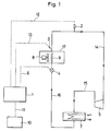
- a computer 1 for expansion valve control calculates the difference between the refrigerant evaporating pressure measured by a pressure sensor 2 and converted into evaporating temperature by the computer 1 and the temperature measured by a temperature sensor 3, i.e, the superheat degree, and controls the refrigerant flow amount of an electronic expansion valve 4 proportionally in a refrigeration circle where the refrigerant is supplied from a compressor 5 to a condenser 7 via a high-pressure gas pipe 15, decreasing the pressure of the refrigerant by the electronic expansion valve 4 via a high-pressure liquid pipe 16, heat-exchanging with the air coming from a fan 8 by an evaporator 9 in the cooling room and returning to the compressor 5 via a low-pressure gas pipe 14,
- the computer 1 is connected to the pressure sensor 2 measuring the refrigerant evaporating pressure, the temperature sensor 3 measuring the refrigerant evaporating temperature placed at the low pressure gas pipe 14 of the lower part of the refrigerant evaporator 9 and the electronic expansion valve 4 via signal cables 12, 13 and 6.
- a control panel 10 for low-temperature air cooler is connected to the abovementioned computer 1 for expansion valve control via a signal cable 11 and controls publicly known defrost devices (not shown in the drawing).
- the temperature measured by the temperature sensor 3 decreases gradually and exceeds the range of the proportional control.
- the computer 1 for expansion valve control detects that the cooling capacity of the refrigerant evaporator 9 has decreased, decreases the maximum valve capacity of the electronic expansion valve 4, compares it with the maximum set valve capacity for starting defrost which is memorized in the computer 1 and starts defrost when the decreased maximum valve capacity falls below the set maximum valve capacity for starting defrost.
- Fig. 3 shows cooling rooms 18 and 19 each provided with a fan 8a, 8b connecting several electronic expansion valves 4a and 4b by diverging the high-pressure liquid pipe 16 and equipped with refrigerant evaporators 9a and 9b.
- 3a and 3b are temperature sensors as above mentioned placed at the lower part of the refrigerant evaporators 9a and 9b before the diverging part to the low-pressure gas pipe 14.
- 6a and 6b are signal cables connecting the electronic expansion valves 4a and 4b and the computer 1 for expansion valve control.
- 12 is a pressure signal cable which connects the pressure sensor 2 placed at the low-pressure gas pipe 14 and the computer 1 as mentioned before.
- 13a and 13b are temperature signal cables connecting the temperature sensors 3a and 3b and the computer 1.
- the computer 1 and the control panel 10 for low-temperature air cooler device controlling the defrost of the evaporators 9a and 9b in the cooling rooms 18 and 19 are connected to each other by signal cables 11a and 11b.
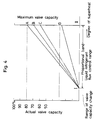
- Fig. 4 shows that point A is the initial setting of the maximum expansion valve capacity and the superheat degrees of the temperature sensors 3, 3a and 3b apply to the heat load change so that the superheat degrees remain within the range of the proportional band I (the superheat degree of the temperature sensor part at the beginning of the expansion valve opening) and II (the superheat degree of the temperature sensor part when the expansion valve has the maximum capacity).
- the actual valve capacity is adjusted one after another on the line IA, IB and IC.
- the superheat degrees of the temperature sensors 3, 3a and 3b will decrease, and when reaching below the superheat 1 of the temperature sensor part at the valve opening, the maximum valve capacity will decrease from point A ⁇ point B ⁇ point C, and when reaching joint D, or when the maximum, minimum or average value of the maximum valve capacity of the expansion valve 4a and 4b reaches to point D or below, the computer 1 for expansion valve control judges it as the most suitable time for starting defrosting and sends defrost start signals to the control panel 10 for low-temperature air coolers via the signal cables 11, 11a and 11b.
- the computer 1 for controlling the expansion valve decreases the maximum valve capacity of the electronic expansion valve 4 and adjusts the capacity of the electronic valve 4 so that the refrigeration capacity of the evaporator 9 and the capacity of the electronic expansion valve 4 will balance.
- the computer 1 for controlling the expansion valve decreases the maximum valve capacity of the electronic expansion valve 4 furthermore, compares it with the set maximum valve capacity which is memorized in the computer 1 in order to set the defrost starting time, judges the time where the maximum valve capacity is the same as or below the set maximum valve capacity for starting defrost as the most suitable time for defrost start and sends defrost starting signals to the control panel 10 of the low-temperature air cooler system.
- This invention saves not only energy, but also prolongs the life time of the compressor by shortening its operation time without damaging the quality of goods stored in a low temperature room thanks to the abovementioned structure.
- the system catches the decrease of the maximum valve capacity of the expansion valves 4, 4a and 4b of the refrigerant evaporators 9, 9a and 9b due to frost accumulation and judges that it is the most suitable time for starting defrosting and starts defrost.
- the system grasps the most suitable time for starting defrosting with certainty by knowing that the decrease of the maximum expansion and starts defrosting of the refrigerant evaporators 9, 9a and 9b in a steady way.
Landscapes
- Engineering & Computer Science (AREA)
- Physics & Mathematics (AREA)
- Mechanical Engineering (AREA)
- Thermal Sciences (AREA)
- General Engineering & Computer Science (AREA)
- Chemical & Material Sciences (AREA)
- Combustion & Propulsion (AREA)
- Defrosting Systems (AREA)
Applications Claiming Priority (2)
| Application Number | Priority Date | Filing Date | Title |
|---|---|---|---|
| JP4049020A JP2694885B2 (ja) | 1992-01-21 | 1992-01-21 | 冷媒蒸発器におけるデフロスト開始時期特定方法 |
| JP49020/92 | 1992-01-21 |
Publications (2)
| Publication Number | Publication Date |
|---|---|
| EP0552906A2 true EP0552906A2 (de) | 1993-07-28 |
| EP0552906A3 EP0552906A3 (en) | 1994-11-30 |
Family
ID=12819444
Family Applications (1)
| Application Number | Title | Priority Date | Filing Date |
|---|---|---|---|
| EP9393300302A Ceased EP0552906A3 (en) | 1992-01-21 | 1993-01-18 | Defrost starting method and device for refrigerant evaporators |
Country Status (3)
| Country | Link |
|---|---|
| EP (1) | EP0552906A3 (de) |
| JP (1) | JP2694885B2 (de) |
| KR (1) | KR930016736A (de) |
Cited By (8)
| Publication number | Priority date | Publication date | Assignee | Title |
|---|---|---|---|---|
| EP0977967A4 (de) * | 1997-04-08 | 2000-10-25 | Heatcraft | Abtausteuerung für raumkühlanlage |
| WO2008094158A1 (en) | 2007-02-02 | 2008-08-07 | Carrier Corporation | Method for operating transport refrigeration unit with remote evaporator |
| CN101451779B (zh) * | 2007-11-28 | 2012-09-05 | 海尔集团公司 | 热泵空调除霜控制方法 |
| CN108800489A (zh) * | 2018-06-20 | 2018-11-13 | 广东美的制冷设备有限公司 | 压缩机绕组加热的控制方法及装置 |
| CN108954730A (zh) * | 2018-06-20 | 2018-12-07 | 广东美的制冷设备有限公司 | 压缩机绕组加热的控制方法及装置 |
| CN109059192A (zh) * | 2018-06-20 | 2018-12-21 | 广东美的制冷设备有限公司 | 压缩机绕组加热的控制方法及装置 |
| CN113776230A (zh) * | 2021-09-25 | 2021-12-10 | 益鹏智能系统科技(上海)有限公司 | 一种天然气制热电子膨胀阀的控制方法及其系统 |
| CN117190388A (zh) * | 2022-05-31 | 2023-12-08 | 佛山市顺德区美的电子科技有限公司 | 一种提高空调器温升速率的控制方法 |
Families Citing this family (3)
| Publication number | Priority date | Publication date | Assignee | Title |
|---|---|---|---|---|
| WO2009093297A1 (ja) * | 2008-01-21 | 2009-07-30 | Mitsubishi Electric Corporation | ヒートポンプ装置及びこのヒートポンプ装置を搭載した空気調和機又は給湯器 |
| WO2013082401A1 (en) * | 2011-12-02 | 2013-06-06 | Welbilt Walk-Ins, Lp | Refrigeration apparatus and method |
| KR101396693B1 (ko) * | 2013-12-23 | 2014-05-16 | 주식회사 지엠에스 | 의료용 냉장고 및 의료용 냉장고의 성에 제상방법 |
Family Cites Families (5)
| Publication number | Priority date | Publication date | Assignee | Title |
|---|---|---|---|---|
| JPS6136671A (ja) * | 1984-07-26 | 1986-02-21 | 三洋電機株式会社 | 冷媒流量制御装置 |
| JPS62131167A (ja) * | 1985-12-03 | 1987-06-13 | 株式会社デンソー | 冷凍サイクル装置 |
| DE3900643A1 (de) * | 1989-01-11 | 1990-07-12 | Schmitz Kuehler Baierbrunn | Verfahren zur leistungsoptimierung von kaeltemittelverdampfern |
| US5233841A (en) * | 1990-01-10 | 1993-08-10 | Kuba Kaltetechnik Gmbh | Method of optimising the performance of refrigerant vaporizers including improved frost control method and apparatus |
| DE4105880A1 (de) * | 1991-02-25 | 1992-08-27 | Kueba Kaeltetechnik Gmbh | Verfahren und vorrichtung zur leistungsoptimierung und abtausteuerung von kaeltemittelverdampfern |
-
1992
- 1992-01-21 JP JP4049020A patent/JP2694885B2/ja not_active Expired - Fee Related
- 1992-09-15 KR KR1019920016712A patent/KR930016736A/ko not_active Abandoned
-
1993
- 1993-01-18 EP EP9393300302A patent/EP0552906A3/en not_active Ceased
Cited By (11)
| Publication number | Priority date | Publication date | Assignee | Title |
|---|---|---|---|---|
| EP0977967A4 (de) * | 1997-04-08 | 2000-10-25 | Heatcraft | Abtausteuerung für raumkühlanlage |
| WO2008094158A1 (en) | 2007-02-02 | 2008-08-07 | Carrier Corporation | Method for operating transport refrigeration unit with remote evaporator |
| EP2118590A4 (de) * | 2007-02-02 | 2014-12-03 | Carrier Corp | Verfahren zum betrieb einer transportkühleinheit mit fernverdampfer |
| CN101451779B (zh) * | 2007-11-28 | 2012-09-05 | 海尔集团公司 | 热泵空调除霜控制方法 |
| CN108800489A (zh) * | 2018-06-20 | 2018-11-13 | 广东美的制冷设备有限公司 | 压缩机绕组加热的控制方法及装置 |
| CN108954730A (zh) * | 2018-06-20 | 2018-12-07 | 广东美的制冷设备有限公司 | 压缩机绕组加热的控制方法及装置 |
| CN109059192A (zh) * | 2018-06-20 | 2018-12-21 | 广东美的制冷设备有限公司 | 压缩机绕组加热的控制方法及装置 |
| CN108800489B (zh) * | 2018-06-20 | 2020-12-22 | 广东美的制冷设备有限公司 | 压缩机绕组加热的控制方法及装置 |
| CN109059192B (zh) * | 2018-06-20 | 2021-04-20 | 广东美的制冷设备有限公司 | 压缩机绕组加热的控制方法及装置 |
| CN113776230A (zh) * | 2021-09-25 | 2021-12-10 | 益鹏智能系统科技(上海)有限公司 | 一种天然气制热电子膨胀阀的控制方法及其系统 |
| CN117190388A (zh) * | 2022-05-31 | 2023-12-08 | 佛山市顺德区美的电子科技有限公司 | 一种提高空调器温升速率的控制方法 |
Also Published As
| Publication number | Publication date |
|---|---|
| JP2694885B2 (ja) | 1997-12-24 |
| KR930016736A (ko) | 1993-08-26 |
| JPH05196343A (ja) | 1993-08-06 |
| EP0552906A3 (en) | 1994-11-30 |
Similar Documents
| Publication | Publication Date | Title |
|---|---|---|
| US5809794A (en) | Feed forward control of expansion valve | |
| US4770000A (en) | Defrosting of refrigerator system out-door heat exchanger | |
| US5214918A (en) | Refrigerator and method for indicating refrigerant amount | |
| US7992398B2 (en) | Refrigeration control system | |
| KR890013430A (ko) | 공기 조화기 및 그 제어방법 | |
| CN100340829C (zh) | 对可逆热泵除霜控制的方法和实施该方法的系统 | |
| US11204184B2 (en) | Air-conditioning apparatus with dirt detection | |
| US4302947A (en) | Heat pump system defrost control | |
| JP2000513797A (ja) | 冷凍システム | |
| EP0552906A2 (de) | Abtauanlassverfahren und -vorrichtung für Kältemittelverdampfer | |
| AU653879B2 (en) | Automatic chiller stopping sequence | |
| EP3140025B1 (de) | Verfahren und vorrichtung zur kühltrocknung eines gases mit zirkulierender kühlflüssigkeit mit umgehungsleitung | |
| EP2230468A2 (de) | Gefriergerät | |
| WO2006087004A1 (en) | Control of a refrigeration circuit with an internal heat exchanger | |
| CA2593090A1 (en) | Refrigeration system having adjustable refrigeration capacity | |
| US5295362A (en) | Electronic slide valve block | |
| JPH0575938B2 (de) | ||
| JPH043865A (ja) | 冷凍サイクル装置 | |
| KR101470538B1 (ko) | 공기조화기의 제어방법 | |
| EP3754269A1 (de) | Verfahren und assoziiertes rechner-speichermedium zur steuerung des abtauzyklus eines dampfkompressionssystems | |
| EP2839225A1 (de) | Steuerung für ein dampfkompressionssystem und verfahren zur steuerung eines dampfkompressionssystems | |
| EP0278701B1 (de) | Abtauanlage für Wärmeaustauscher | |
| JPH07305903A (ja) | 冷凍装置の制御装置 | |
| JPS5829827Y2 (ja) | 冷凍装置の温度制御装置 | |
| CA2163076C (en) | Refrigeration system with heat reclaim and method of operation |
Legal Events
| Date | Code | Title | Description |
|---|---|---|---|
| PUAI | Public reference made under article 153(3) epc to a published international application that has entered the european phase |
Free format text: ORIGINAL CODE: 0009012 |
|
| AK | Designated contracting states |
Kind code of ref document: A2 Designated state(s): CH DE DK ES FR GB IT LI SE |
|
| PUAL | Search report despatched |
Free format text: ORIGINAL CODE: 0009013 |
|
| AK | Designated contracting states |
Kind code of ref document: A3 Designated state(s): CH DE DK ES FR GB IT LI SE |
|
| 17P | Request for examination filed |
Effective date: 19950410 |
|
| 17Q | First examination report despatched |
Effective date: 19960429 |
|
| GRAG | Despatch of communication of intention to grant |
Free format text: ORIGINAL CODE: EPIDOS AGRA |
|
| 18R | Application refused |
Effective date: 19971004 |