EP0553802B1 - Mécanisme de commande pour une barrière ou similaire - Google Patents
Mécanisme de commande pour une barrière ou similaire Download PDFInfo
- Publication number
- EP0553802B1 EP0553802B1 EP93101242A EP93101242A EP0553802B1 EP 0553802 B1 EP0553802 B1 EP 0553802B1 EP 93101242 A EP93101242 A EP 93101242A EP 93101242 A EP93101242 A EP 93101242A EP 0553802 B1 EP0553802 B1 EP 0553802B1
- Authority
- EP
- European Patent Office
- Prior art keywords
- gear
- crank
- shaft
- driving device
- spring
- Prior art date
- Legal status (The legal status is an assumption and is not a legal conclusion. Google has not performed a legal analysis and makes no representation as to the accuracy of the status listed.)
- Expired - Lifetime
Links
- 230000004888 barrier function Effects 0.000 description 17
- 230000005540 biological transmission Effects 0.000 description 10
- 230000001133 acceleration Effects 0.000 description 1
- 230000006835 compression Effects 0.000 description 1
- 238000007906 compression Methods 0.000 description 1
- 238000005265 energy consumption Methods 0.000 description 1
- 230000036316 preload Effects 0.000 description 1
- 239000007787 solid Substances 0.000 description 1
Images


Classifications
-
- E—FIXED CONSTRUCTIONS
- E01—CONSTRUCTION OF ROADS, RAILWAYS, OR BRIDGES
- E01F—ADDITIONAL WORK, SUCH AS EQUIPPING ROADS OR THE CONSTRUCTION OF PLATFORMS, HELICOPTER LANDING STAGES, SIGNS, SNOW FENCES, OR THE LIKE
- E01F13/00—Arrangements for obstructing or restricting traffic, e.g. gates, barricades ; Preventing passage of vehicles of selected category or dimensions
- E01F13/04—Arrangements for obstructing or restricting traffic, e.g. gates, barricades ; Preventing passage of vehicles of selected category or dimensions movable to allow or prevent passage
- E01F13/06—Arrangements for obstructing or restricting traffic, e.g. gates, barricades ; Preventing passage of vehicles of selected category or dimensions movable to allow or prevent passage by swinging into open position about a vertical or horizontal axis parallel to the road direction, i.e. swinging gates
Definitions
- the invention relates to a drive device for a between two end positions by a predetermined pivot angle of preferably substantially 90 ° pivotable barrier boom or the like with an electric drive motor carried by a carrier, which rotates a tree shaft back and forth via a gear transmission and crank mechanism, and with am Supporting compensating spring for the barrier.
- Such a drive device is known from DE-OS 37 15 936, in which a drive motor is mounted in a housing which at the same time carries bearings for mounting a tree shaft for a barrier tree or the like, the drive motor via a gear mechanism and a crank mechanism with the tree shaft is coupled to pivot the latter back and forth by 90 °, and additional compensating springs are provided between the carrier and a lever engaging the tree shaft, which is part of the crank mechanism, for relieving the torque of the drive gear motor.
- the tree wave or its storage and the compensation springs form a unit here.
- the drive geared motor has to be designed relatively strong despite the compensating springs, since the crank gear provides a non-uniform transmission ratio and therefore the torque relief by the compensating springs does not work optimally.
- the required travel requires a relatively long spring crank arm, which affects a compact design.
- the object of this invention is to provide a drive device according to the preamble of claim 1, in which the torque load and the electrical energy consumption of the drive gear motor are significantly reduced and smaller crank arms are required for the compensating springs.
- the compensating spring acts via a crank on a gear shaft of a gear connected downstream of the drive motor, which gear shaft rotates back and forth by double the pivoting angle of the barrier boom.
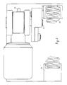
- Fig. 1 shows schematically in section a drive device for a barrier.
- FIG. 2 shows a top view of the drive device from FIG. 1.
- Fig. 3 shows the course of the transmission torque (ordinate) for the drive device of Fig. 1 and 2 plotted against the angle of rotation of the transmission shaft.
- the drive device shown comprises a carrier 1, which can preferably be designed as a separate part fastened to a barrier housing 2 and carries an electric drive motor 3.
- the drive motor 3 is coupled to a crank mechanism via a gear 4, for example a worm gear.
- the crank mechanism comprises a double crank 6 fastened on the transmission shaft 5 of the transmission 4, which is fastened via a link 7 articulated thereon with a barrier boom 9 or the like which is attached to the tree shaft 8 for an essentially 90 ° pivotable between a closed horizontal and an open vertical position Lever 10 is articulated.
- the tree shaft 8 is mounted on the carrier 1 via, for example, two bearing blocks 11, the Lever 10 in the area between the two bearing blocks 11 engages.
- the gear shaft 5 is connected to the double crank 6, which on the one hand - as already described - causes the movement of the tree shaft 8 and the barrier boom 9, on the other hand contains a rotatably mounted shaft 12 which is designed at its free end as a spring cup. This accommodates a compensating spring 13 designed as a compression spring, which is supported on the counter-holder 14, which is screwed to the carrier 1.
- the drive motor 3 rotates the transmission output shaft 5 by twice the swivel angle of the barrier boom 9, i.e. in the illustrated embodiment by 180 °, so that the spring cup 12 with the compensating spring 13 is pivoted by this angle between the illustrated end position (barrier boom 9 open) and an end position (barrier boom 9 closed).
- the crank mechanism is designed in such a way that it causes the barrier boom 9 to pivot by 90 ° when the transmission shaft 5 is rotated through 180 °.
- the bore for the spring cup shaft 12 is located opposite the pin for the crank mechanism, consisting of the parts double crank 6, intermediate member 7 and lever 10 by the angle ⁇ 40 ° with a horizontally arranged compensating spring 13 and with a vertically mounted compensating spring rotated by 130 °.
- the total torque in the 0 ° position is just positive.
- the total torque is somewhat larger negative, which causes a preload against the closed position, i.e. the opening of the barrier boom 9, i.e. the beginning of its pivoting into its vertical position is supported.
- the size of the moments at 0 ° and 180 ° can be influenced by appropriate choice of the angle ⁇ . In the dead positions, there are only small torques from the crank mechanism and also from the compensating spring 13.
- a relatively weak drive motor 3 can be used, at the same time no large crank arm is required for the compensating spring 13.
- the unit formed by the carrier 1, which comprises the drive motor 3, the gear 4, the compensating spring arrangement and the crank mechanism, can be designed separately replaceable.
- the gear 4 can contain a releasable slip clutch, which enables an emergency opening of the barrier boom 9.
- the emergency opening when the slip clutch is released is supported by the compensating spring 13 due to the resulting negative torque in the 180 ° position of the transmission 4 corresponding to the 90 ° horizontal position of the barrier boom 9.
- An emergency opening with a hand crank can be done with the free drive shaft journal when the slip clutch is closed 15 can be made.
Landscapes
- Engineering & Computer Science (AREA)
- Architecture (AREA)
- Civil Engineering (AREA)
- Structural Engineering (AREA)
- Transmission Devices (AREA)
Claims (10)
- Dispositif d'entraînement pour une barrière articulée ou analogue (9), ladite barrière étant susceptible de pivoter entre deux positions finales, avec un angle prédéterminé de préférence de l'ordre de 90°, ledit dispositif comportant un moteur électrique (3) porté par un support (1), ledit moteur appliquant, par l'intermédiaire d'un engrenage (4) et d'une transmission à bielles (6, 7, 10), un mouvement rotatif alterné à un arbre (8) de la barrière, ainsi qu'un ressort de compensation (13) pour la barrière, ledit ressort s'appuyant sur le support (1), caractérisé en ce que le ressort de compensation (13) agit, au moyen d'une bielle (6) de la transmission à bielles (6, 7, 10), sur un arbre d'engrenage (5) d'un engrenage (4) monté en aval du moteur (3), ledit arbre d'engrenage (5) exécutant un mouvement rotatif alterné du double de l'angle de pivotement de la barrière (9).
- Dispositif d'entraînement selon la revendication 1, caractérisé en ce que le ressort de compensation (13) sert de ressort de compression.
- Dispositif d'entraînement selon la revendication 1 ou 2, caractérisé en ce que le ressort de compensation (13) est accouplé à la bielle (6) par l'intermédiaire d'un arbre (12) muni d'un logement de ressort et logé dans un alésage de la bielle (6).
- Dispositif d'entraînement selon la revendication 3, caractérisé en ce que l'alésage pour l'arbre à logement de ressort (12) est agencé dans la bielle (6) à un angle ( β ) d'environ 40° autour de l'axe de l'arbre d'engrenage (5), ledit angle étant pris, alors que le ressort de compensation (13) s'étend horizontalement, par rapport à la ligne reliant l'axe de l'arbre d'engrenage (5) à l'axe d'une articulation située sur la bielle (6) et prévue pour relier ladite bielle à la partie suivante (7) de la transmission à bielles (6, 7, 10), de telle sorte que, dans la position finale fermée de la barrière (9), il en résulte pour l'engrenage (4) un couple de rotation faible s'opposant à la position de fermeture.
- Dispositif d'entraînement selon la revendication 4, caractérisé en ce que l'alésage de l'arbre à logement de ressort (12) est agencé à un angle ( β ) d'environ 40° autour de l'axe de l'arbre d'engrenage (5), ledit angle étant pris lorsque le ressort de compensation (13) s'étend horizontalement.
- Dispositif d'entraînement selon l'une des revendications 3 à 5, caractérisé en ce que l'alésage pour l'arbre à logement de ressort (12) est agencé dans la bielle (6) à un angle ( β ) autour de l'axe de l'arbre d'engrenage (5), ledit angle étant pris par rapport à la ligne reliant l'axe de l'arbre d'engrenage (5) à l'axe d'une articulation située sur la bielle (6) et prévue pour relier ladite bielle à la partie suivante (7) de la transmission à bielles (6, 7, 10), de telle sorte que le ressort de compensation (13), au moyen d'une tension initiale adéquate dans la position finale ouverte de la barrière, exerce sur la barrière (9) en position fermée un faible couple de rotation.
- Dispositif d'entraînement selon l'une des revendications 1 à 6, caractérisé en ce que l'engrenage (4) est un engrenage à vis sans fin.
- Dispositif d'entraînement selon l'une des revendications 1 à 7, caractérisé en ce que l'engrenage (4) comprend un embrayage à friction débrayable.
- Dispositif d'entraînement selon l'une des revendications 1 à 8, caractérisé en ce que l'engrenage (4) comporte un tenon libre (15) agencé sur l'arbre d'entraînement, de sorte à permettre une manoeuvre d'urgence en utilisant une manivelle.
- Dispositif d'entraînement selon l'une des revendications 1 à 9, caractérisé en ce que le support (1), comportant le moteur d'entraînement (3), l'engrenage (4), la transmission à bielles (6, 7, 10) et le ressort de compensation (13), est réalisé sous la forme d'un bloc à éléments interchangeables.
Applications Claiming Priority (2)
| Application Number | Priority Date | Filing Date | Title |
|---|---|---|---|
| DE4202584 | 1992-01-30 | ||
| DE4202584A DE4202584A1 (de) | 1992-01-30 | 1992-01-30 | Antriebsvorrichtung fuer eine schranke oder dergleichen |
Publications (3)
| Publication Number | Publication Date |
|---|---|
| EP0553802A2 EP0553802A2 (fr) | 1993-08-04 |
| EP0553802A3 EP0553802A3 (en) | 1993-09-15 |
| EP0553802B1 true EP0553802B1 (fr) | 1995-08-09 |
Family
ID=6450578
Family Applications (1)
| Application Number | Title | Priority Date | Filing Date |
|---|---|---|---|
| EP93101242A Expired - Lifetime EP0553802B1 (fr) | 1992-01-30 | 1993-01-28 | Mécanisme de commande pour une barrière ou similaire |
Country Status (2)
| Country | Link |
|---|---|
| EP (1) | EP0553802B1 (fr) |
| DE (2) | DE4202584A1 (fr) |
Cited By (1)
| Publication number | Priority date | Publication date | Assignee | Title |
|---|---|---|---|---|
| DE102010012148A1 (de) | 2010-03-20 | 2011-09-22 | Rhein-Getriebe Gmbh | Antriebsvorrichtung für eine Schranke oder dergleichen |
Families Citing this family (3)
| Publication number | Priority date | Publication date | Assignee | Title |
|---|---|---|---|---|
| DE4435601A1 (de) * | 1994-10-05 | 1996-04-11 | Malkmus Doernemann Carola | Antriebsvorrichtung für eine Schranke oder dergleichen |
| AT402311B (de) * | 1995-03-20 | 1997-04-25 | Skidata Gmbh | Absperreinrichtung |
| DE202010003545U1 (de) | 2010-03-13 | 2010-07-22 | Magnetic Autocontrol Gmbh | Antriebsvorrichtung |
Family Cites Families (4)
| Publication number | Priority date | Publication date | Assignee | Title |
|---|---|---|---|---|
| DE1991565U (de) * | 1968-04-26 | 1968-08-14 | Parkautomatic Hans Farmont | Schranke. |
| DE8516062U1 (de) * | 1985-06-01 | 1985-07-18 | Rhein-Getriebe Gmbh, 4005 Meerbusch | Schrankenantrieb |
| DE3715936A1 (de) * | 1987-05-13 | 1988-12-01 | Magnetic Elektromotoren Gmbh | Antriebsvorrichtung fuer schranken od. dgl. |
| DE9000478U1 (de) * | 1990-01-17 | 1990-03-01 | K. & A. Knödler GmbH, 7302 Ostfildern | Antriebsvorrichtung für eine Schranke |
-
1992
- 1992-01-30 DE DE4202584A patent/DE4202584A1/de not_active Withdrawn
-
1993
- 1993-01-28 EP EP93101242A patent/EP0553802B1/fr not_active Expired - Lifetime
- 1993-01-28 DE DE59300432T patent/DE59300432D1/de not_active Expired - Lifetime
Cited By (1)
| Publication number | Priority date | Publication date | Assignee | Title |
|---|---|---|---|---|
| DE102010012148A1 (de) | 2010-03-20 | 2011-09-22 | Rhein-Getriebe Gmbh | Antriebsvorrichtung für eine Schranke oder dergleichen |
Also Published As
| Publication number | Publication date |
|---|---|
| EP0553802A3 (en) | 1993-09-15 |
| DE59300432D1 (de) | 1995-09-14 |
| EP0553802A2 (fr) | 1993-08-04 |
| DE4202584A1 (de) | 1993-08-05 |
Similar Documents
| Publication | Publication Date | Title |
|---|---|---|
| DE4218507C2 (de) | Fensterstellglied | |
| EP0129157B1 (fr) | Bras de robot | |
| DE19623317C2 (de) | Vorrichtung zum Betätigen von einseitig angelenkten Bauteilen | |
| DE4110170A1 (de) | Wischervorrichtung | |
| EP0716004B1 (fr) | Porte pivotante et coulissante pour véhicules de transport de personnes | |
| DD219985A5 (de) | Ausschwingtuer mit betaetigungseinrichtung | |
| DE3607078A1 (de) | Arm-fensterheber, insbesondere fuer kraftfahrzeuge | |
| EP0553802A2 (fr) | Mécanisme de commande pour une barrière ou similaire | |
| DE69420617T2 (de) | Fensterbedienungsvorrichtung mit Gewichtsausgleich | |
| EP0222995B1 (fr) | Battant coulissant en forme d'une fenêtre, porte ou des choses pareilles | |
| DE3416466C2 (fr) | ||
| DE2923421C2 (de) | Antriebsvorrichtung für einen Tür- bzw. Torflügel | |
| DE7021751U (de) | Getriebeanordnung fuer fensterheber. | |
| DE3546591C2 (en) | Setting-out device for windows, rising roofs or the like pivotable about an axis and belonging to motor vehicles | |
| WO2018069292A1 (fr) | Ensemble transmission pour un entraînement à broche, entraînement à broche et siège de véhicule | |
| DE718656C (de) | Kippsicherung fuer Kraftfahrdrehleitern, Maste, Traeger o. dgl. | |
| DE69015553T2 (de) | Verfahren und Vorrichtung für das Heben und Entfernen von einer normalerweise horizontalen Plattform. | |
| EP0593791B1 (fr) | Dispositif pour déplacer un appareil dentaire | |
| DE3207418A1 (de) | Frontmaehwerk | |
| DE2614753A1 (de) | Vorrichtung zum oeffnen und schliessen von tueren | |
| DE2200348C3 (de) | Anlenkvorrichtung für einen lastabhängigen Bremskraftregler an Kraftfahrzeugen | |
| DE3514306A1 (de) | Hub- und kippvorrichtung zum entleeren von muellgefaessen | |
| DE879623C (de) | Fahrzeug mit an der Fahrzeugfront angebrachter Maehvorrichtung | |
| DE2111680A1 (de) | Brueckenlegegeraet | |
| DE3904086A1 (de) | Verstelleinrichtung, insbesondere fuer eine kopfstuetze in einem kraftwagen |
Legal Events
| Date | Code | Title | Description |
|---|---|---|---|
| PUAI | Public reference made under article 153(3) epc to a published international application that has entered the european phase |
Free format text: ORIGINAL CODE: 0009012 |
|
| PUAL | Search report despatched |
Free format text: ORIGINAL CODE: 0009013 |
|
| AK | Designated contracting states |
Kind code of ref document: A2 Designated state(s): DE FR IT NL |
|
| AK | Designated contracting states |
Kind code of ref document: A3 Designated state(s): DE FR IT NL |
|
| 17P | Request for examination filed |
Effective date: 19930923 |
|
| 17Q | First examination report despatched |
Effective date: 19941118 |
|
| GRAA | (expected) grant |
Free format text: ORIGINAL CODE: 0009210 |
|
| AK | Designated contracting states |
Kind code of ref document: B1 Designated state(s): DE FR IT NL |
|
| REF | Corresponds to: |
Ref document number: 59300432 Country of ref document: DE Date of ref document: 19950914 |
|
| ET | Fr: translation filed | ||
| ITF | It: translation for a ep patent filed | ||
| PLBE | No opposition filed within time limit |
Free format text: ORIGINAL CODE: 0009261 |
|
| STAA | Information on the status of an ep patent application or granted ep patent |
Free format text: STATUS: NO OPPOSITION FILED WITHIN TIME LIMIT |
|
| 26N | No opposition filed | ||
| PGFP | Annual fee paid to national office [announced via postgrant information from national office to epo] |
Ref country code: NL Payment date: 20080115 Year of fee payment: 16 Ref country code: IT Payment date: 20080125 Year of fee payment: 16 |
|
| PGFP | Annual fee paid to national office [announced via postgrant information from national office to epo] |
Ref country code: FR Payment date: 20080111 Year of fee payment: 16 |
|
| NLV4 | Nl: lapsed or anulled due to non-payment of the annual fee |
Effective date: 20090801 |
|
| REG | Reference to a national code |
Ref country code: FR Ref legal event code: ST Effective date: 20091030 |
|
| PG25 | Lapsed in a contracting state [announced via postgrant information from national office to epo] |
Ref country code: NL Free format text: LAPSE BECAUSE OF NON-PAYMENT OF DUE FEES Effective date: 20090801 |
|
| PG25 | Lapsed in a contracting state [announced via postgrant information from national office to epo] |
Ref country code: FR Free format text: LAPSE BECAUSE OF NON-PAYMENT OF DUE FEES Effective date: 20090202 |
|
| PGFP | Annual fee paid to national office [announced via postgrant information from national office to epo] |
Ref country code: DE Payment date: 20100319 Year of fee payment: 18 |
|
| PG25 | Lapsed in a contracting state [announced via postgrant information from national office to epo] |
Ref country code: IT Free format text: LAPSE BECAUSE OF NON-PAYMENT OF DUE FEES Effective date: 20090128 |
|
| REG | Reference to a national code |
Ref country code: DE Ref legal event code: R119 Ref document number: 59300432 Country of ref document: DE Effective date: 20110802 |
|
| PG25 | Lapsed in a contracting state [announced via postgrant information from national office to epo] |
Ref country code: DE Free format text: LAPSE BECAUSE OF NON-PAYMENT OF DUE FEES Effective date: 20110802 |