EP0553816A2 - Scheibenförmiges Aufzeichnungsmedium und Adressenunterscheidungsschaltung dafür - Google Patents
Scheibenförmiges Aufzeichnungsmedium und Adressenunterscheidungsschaltung dafür Download PDFInfo
- Publication number
- EP0553816A2 EP0553816A2 EP93101316A EP93101316A EP0553816A2 EP 0553816 A2 EP0553816 A2 EP 0553816A2 EP 93101316 A EP93101316 A EP 93101316A EP 93101316 A EP93101316 A EP 93101316A EP 0553816 A2 EP0553816 A2 EP 0553816A2
- Authority
- EP
- European Patent Office
- Prior art keywords
- bits
- data
- address
- disc
- addresses
- Prior art date
- Legal status (The legal status is an assumption and is not a legal conclusion. Google has not performed a legal analysis and makes no representation as to the accuracy of the status listed.)
- Granted
Links
Images


Classifications
-
- G—PHYSICS
- G11—INFORMATION STORAGE
- G11B—INFORMATION STORAGE BASED ON RELATIVE MOVEMENT BETWEEN RECORD CARRIER AND TRANSDUCER
- G11B27/00—Editing; Indexing; Addressing; Timing or synchronising; Monitoring; Measuring tape travel
- G11B27/10—Indexing; Addressing; Timing or synchronising; Measuring tape travel
- G11B27/19—Indexing; Addressing; Timing or synchronising; Measuring tape travel by using information detectable on the record carrier
-
- G—PHYSICS
- G11—INFORMATION STORAGE
- G11B—INFORMATION STORAGE BASED ON RELATIVE MOVEMENT BETWEEN RECORD CARRIER AND TRANSDUCER
- G11B11/00—Recording on or reproducing from the same record carrier wherein for these two operations the methods are covered by different main groups of groups G11B3/00 - G11B7/00 or by different subgroups of group G11B9/00; Record carriers therefor
- G11B11/10—Recording on or reproducing from the same record carrier wherein for these two operations the methods are covered by different main groups of groups G11B3/00 - G11B7/00 or by different subgroups of group G11B9/00; Record carriers therefor using recording by magnetic means or other means for magnetisation or demagnetisation of a record carrier, e.g. light induced spin magnetisation; Demagnetisation by thermal or stress means in the presence or not of an orienting magnetic field
- G11B11/105—Recording on or reproducing from the same record carrier wherein for these two operations the methods are covered by different main groups of groups G11B3/00 - G11B7/00 or by different subgroups of group G11B9/00; Record carriers therefor using recording by magnetic means or other means for magnetisation or demagnetisation of a record carrier, e.g. light induced spin magnetisation; Demagnetisation by thermal or stress means in the presence or not of an orienting magnetic field using a beam of light or a magnetic field for recording by change of magnetisation and a beam of light for reproducing, i.e. magneto-optical, e.g. light-induced thermomagnetic recording, spin magnetisation recording, Kerr or Faraday effect reproducing
- G11B11/1055—Disposition or mounting of transducers relative to record carriers
- G11B11/10556—Disposition or mounting of transducers relative to record carriers with provision for moving or switching or masking the transducers in or out of their operative position
- G11B11/10563—Access of indexed parts
- G11B11/10565—Marks for track change, e.g. prepits, gray codes
-
- G—PHYSICS
- G11—INFORMATION STORAGE
- G11B—INFORMATION STORAGE BASED ON RELATIVE MOVEMENT BETWEEN RECORD CARRIER AND TRANSDUCER
- G11B20/00—Signal processing not specific to the method of recording or reproducing; Circuits therefor
- G11B20/10—Digital recording or reproducing
- G11B20/12—Formatting, e.g. arrangement of data block or words on the record carriers
-
- G—PHYSICS
- G11—INFORMATION STORAGE
- G11B—INFORMATION STORAGE BASED ON RELATIVE MOVEMENT BETWEEN RECORD CARRIER AND TRANSDUCER
- G11B27/00—Editing; Indexing; Addressing; Timing or synchronising; Monitoring; Measuring tape travel
- G11B27/10—Indexing; Addressing; Timing or synchronising; Measuring tape travel
- G11B27/19—Indexing; Addressing; Timing or synchronising; Measuring tape travel by using information detectable on the record carrier
- G11B27/24—Indexing; Addressing; Timing or synchronising; Measuring tape travel by using information detectable on the record carrier by sensing features on the record carrier other than the transducing track ; sensing signals or marks recorded by another method than the main recording
-
- G—PHYSICS
- G11—INFORMATION STORAGE
- G11B—INFORMATION STORAGE BASED ON RELATIVE MOVEMENT BETWEEN RECORD CARRIER AND TRANSDUCER
- G11B7/00—Recording or reproducing by optical means, e.g. recording using a thermal beam of optical radiation by modifying optical properties or the physical structure, reproducing using an optical beam at lower power by sensing optical properties; Record carriers therefor
- G11B7/007—Arrangement of the information on the record carrier, e.g. form of tracks, actual track shape, e.g. wobbled, or cross-section, e.g. v-shaped; Sequential information structures, e.g. sectoring or header formats within a track
- G11B7/00745—Sectoring or header formats within a track
-
- G—PHYSICS
- G11—INFORMATION STORAGE
- G11B—INFORMATION STORAGE BASED ON RELATIVE MOVEMENT BETWEEN RECORD CARRIER AND TRANSDUCER
- G11B20/00—Signal processing not specific to the method of recording or reproducing; Circuits therefor
- G11B20/10—Digital recording or reproducing
- G11B2020/1087—Digital recording or reproducing wherein a selection is made among at least two alternative ways of processing
- G11B2020/10879—Digital recording or reproducing wherein a selection is made among at least two alternative ways of processing the kind of record carrier being the selection criterion
-
- G—PHYSICS
- G11—INFORMATION STORAGE
- G11B—INFORMATION STORAGE BASED ON RELATIVE MOVEMENT BETWEEN RECORD CARRIER AND TRANSDUCER
- G11B2220/00—Record carriers by type
- G11B2220/20—Disc-shaped record carriers
- G11B2220/25—Disc-shaped record carriers characterised in that the disc is based on a specific recording technology
- G11B2220/2525—Magneto-optical [MO] discs
-
- G—PHYSICS
- G11—INFORMATION STORAGE
- G11B—INFORMATION STORAGE BASED ON RELATIVE MOVEMENT BETWEEN RECORD CARRIER AND TRANSDUCER
- G11B2220/00—Record carriers by type
- G11B2220/20—Disc-shaped record carriers
- G11B2220/25—Disc-shaped record carriers characterised in that the disc is based on a specific recording technology
- G11B2220/2537—Optical discs
-
- G—PHYSICS
- G11—INFORMATION STORAGE
- G11B—INFORMATION STORAGE BASED ON RELATIVE MOVEMENT BETWEEN RECORD CARRIER AND TRANSDUCER
- G11B27/00—Editing; Indexing; Addressing; Timing or synchronising; Monitoring; Measuring tape travel
- G11B27/10—Indexing; Addressing; Timing or synchronising; Measuring tape travel
- G11B27/19—Indexing; Addressing; Timing or synchronising; Measuring tape travel by using information detectable on the record carrier
- G11B27/28—Indexing; Addressing; Timing or synchronising; Measuring tape travel by using information detectable on the record carrier by using information signals recorded by the same method as the main recording
- G11B27/30—Indexing; Addressing; Timing or synchronising; Measuring tape travel by using information detectable on the record carrier by using information signals recorded by the same method as the main recording on the same track as the main recording
- G11B27/3027—Indexing; Addressing; Timing or synchronising; Measuring tape travel by using information detectable on the record carrier by using information signals recorded by the same method as the main recording on the same track as the main recording used signal is digitally coded
Definitions
- This invention relates to a disc-shaped recording medium, such as an optical disc, and an address data discriminating circuit for discriminating addresses, such as track addresses, on the disc-shaped recording medium.
- Such disc-shaped recording medium includes an optical disc and a magneto-optical disc.
- An example of the disc-shaped recording medium is a magneto-optical disc having a format as proposed in ISO/IEC 10089:1991(E).
- a track at a radial distance of 30 mm from the disc center bears a zero- track address
- tracks at a radially outer side of the zero track address or within a range of from 30 mm to 60 mm in terms of a disc radius are indicated by (+) side track addresses, while those at a radially inner side of the zero track address are indicated by (-) side track addresses.
- the radially outer side region of the disc, having the plus (+) side tracks, is a user area, while the tracks on the radially inner side of the zero track address at the radius of 30 mm are used as test tracks or control data tracks.
- the above-mentioned track addresses are recorded by embossed bits on the optical disc by 2 bytes or 16 bits.
- the current track pitch is 1.6 ⁇ m. It has recently been envisaged to narrow the track pitch for increasing the disc capacity. For example, it is contemplated to use a track pitch of 1.4 ⁇ m.
- the track pitch of, for example, 1.4 ⁇ m is used in place of the currently employed track pith of 1.6 ⁇ m
- the number of tracks and that of sectors is increased progressively towards the outer periphery of the disc if the disc is to be rotated with modified constant angular velocity (MCAV), such that, if the above-mentioned format is to be maintained, it becomes impossible to represent all of the tracks at the radially outer side or (+) side of the disc.
- the radially inner side or (-) side tracks need to be formated at least to a radius of 29.52 mm. This can be done without any inconvenience because there are about 300 tracks in this region for the track pitch of 1.6 ⁇ m.
- tracks of the (+) side up to the +32767th track and tracks of the (-) side up to the -32768th track are represented by 2's complement representation of 2 bytes or 16 bits, so that, if the track pitch of 1.6 ⁇ m, the totality of the tracks can be represented by the 2's complement representation of the 16 bits.
- the track pitch of 1.4 ⁇ m is used, there is a possibility that the number of tracks on one side of the zero address track exceed 32768, such that it becomes impossible to indicate the totality of tracks by 2's complement representation of 16 bits.
- a recording medium in the form of a disc in which locations on the disc other than a predetermined location as set to zero-address are represented by (+) side addresses and (-) side addresses with respect to the zero address, and in which the information concerning these addresses are at least recorded as address data constituted by N bits, wherein one of the (+) side address data and the (-) side address data are recorded in the form of the N bit data of which upper n bits, where N > n, are all set to one of the binary states, with the remaining bits of said N bits representing the addresses, and wherein the other of said (+) side address data and said (-) side address data are recorded as data by said N bits exclusive of those data in which the upper n bits are in said one of said binary states.
- an address discriminating circuit for a recording medium in the form of a disc in which locations on the disc other than a predetermined location as set to a zero-address are represented by (+) side addresses and (-) side addresses with respect to the zero address, and in which the information concerning these addresses are at least recorded as address data constituted by N bits, one of the (+) side address data and the (-) side address data being recorded in the form of the N bit data of which upper n bits, where N > n, are all set to one of the binary states, with the remaining bits of the N bits representing the addresses, the other of the (+) side address data and the (-) side address data are recorded as data by the N bits exclusive of those data in which the upper n bits are in the aforementioned one of the binary states, wherein the address discriminating circuit comprises binary state discriminating means for discriminating the binary states of the upper n bits of the N bit address data read from the recording medium, and discriminating means for deciding the address data to be address data on said
- the polarity or sign of the track addresses, pre-recorded as embossed bits on the disc is represented by using particular upper order bits (upper n bits) in the manner of sign bits, without using the most significant bit (MSB) as a sign bit, as in customary 2's complement representation.
- the polarity or sign is discriminated by ANDing the upper n bits.
- the disc-shaped recording medium and the address discriminating circuit are so arranged and constructed that, by taking advantage of the fact that the number of addresses required for one of the (+) side and the (-) side according to the conventional format, such as the (-) side, is lesser than that required for the other side, for example, the (+) side, the upper n bits of the N bits are used in the manner of sign bits for representing the addresses for the above-mentioned one side for indicating that the address is for the one side, and for representing the address by the remaining bits, while the addresses for the other side are represented by the N bits inclusive of the upper n bits, with the upper n bits not being all in the aforementioned one of the binary states indicating that the addresses are those for the above-mentioned other side.
- the above-described arrangement renders it possible to cope with increase in the number of track addresses on the other side of the disc.
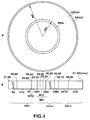
- Fig.1 is a plan view showing a disc-shaped recording medium embodying the present invention, and various regions thereof.
- Fig.2 shows 16-bit address data employed in the present invention.
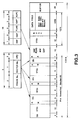
- Fig.3 shows a sector format employed in the present invention.
- Fig.4 is a circuit diagram showing a schematic arrangement of an address discriminating circuit for the disc-shaped recording medium embodying the present invention.
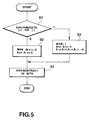
- Fig.5 is a flow chart for illustrating sign discrimination and data summation according to the present invention.
- Fig.6 is a block circuit diagram showing the schematic arrangement of the disc-shaped recording medium and a recording and/or reproducing apparatus employing the disc-shaped recording medium.
- the disc-shaped recording medium according to the present invention is such a disc in which, as shown in Fig.1, a predetermined position on the disc D, such as a track at a radius of 30 mm, is a zero-address track, with the remaining positions on the disc D being represented by addresses on the plus (+) side and those on the minus(-) side, with respect to the zero address, and with data of the addresses being at least recorded as address data constituted by N bits, such as by 16 bits.
- address data of the remaining region are recorded in the form of 16 bit data exclusive of those data in which the upper order four bits of the 16 bits are all in the above-mentioned one state of the binary number system, herein all "1", in other words, are recorded in the form of the 16 bit data in which at least one "0" is present in the upper order four bits.
- the upper four bits b15, b14, b13 and b12 of the 16 bits b15, b14, ⁇ b0 of the address data are all set to, for example, "1", with the remaining bits b11, ⁇ b0 indicating the addresses
- the addresses are indicated by the 16 bits b15, b14, ⁇ b0, exclusive of those 16 bit data in which the upper four bits b15, b14, b13 and b12 are all "1", as shown in Fig.2. It is such address data that are recorded in an inner extension region AR IN of the disc D, as hereinafter explained.
- up to the -4096th address may be represented for the (-) or radially inner region, whereas up to the +61439th address may be represented for the (+) or radially outer region, in other words, it becomes possible to represent the number of tracks such that -4096 ⁇ number of tracks ⁇ +61439.
- the tracks for the (-) region or the radially inner region of the disc are test tacks or control data tracks etc, as stated hereinbefore, and it suffices to represent about 1000 or less tracks, specifically, 400 to 800 tracks, so that the track pitch may be set to 1.4 ⁇ m without raising any particular problems.
- the disc D has a format according to ISO/IEC 10089:1991 (E) and has a spirally extending track.
- the radially inner expansion region AR IN is formed in a region from radius 27 mm to radius 30 mm
- a user area (user recordable area) AR USE is formed in a region from radius 30 mm to radius 60 mm
- a radially outer extension region AR OUT is formed in a region from radius 60 mm to radius 61 mm, from the center of the disc D, as shown at A in Fig.1.
- a reflective mirror area RZ is formed in an area from radius 27.00 mm to radius 29.00 mm
- a PEP control track area CTZ is formed in the adjacent area from radius 29.00 mm to radius 29.50 mm, as shown at B in Fig.1.
- the PEP data are rotation control data, of data for modulation system, disc type etc. of the optical disc, recorded by embossed bits.
- a transition area TZ is formed in a zone of from radius 29.50 mm to radius 29.52 mm radially outwardly of the PEP control track area CTZ, and a radially inner SFP control track area CTZ, bearing SFP data, is formed in an adjacent zone of from radius 29.52 mm to radius 29.70 mm.
- the SFP data is system data including PEP data and representing optical disc medium data, power or pulse width etc. of the recording/reproducing laser power, and is recorded in the form of embossing pits.
- An area of radius 29.70 mm to radius 30.00 mm, radially outside the radially inner SFP control track area ICTZ, is defined as a radially inner area for producer use IMZ, whereas an area of radius 29.80 mm to radius 29.90 mm, sandwiched between a first guard band GB1 of radius 29.70 mm to radius 29.80 mm and a second guard band GB2 of radius 29.80 mm to 29.90 mm, is used as a producer test area MTZ.
- an area of from radius 60.00 mm to radius 60.15 mm is defined as a radially outer area for producer use OMZ
- a radially outer SFP control track area OCTZ is formed in an adjacent area of from radius 60.15 mm to radius 61.50 mm
- an adjacent area of from radius 60.50 mm to radius 61.00 mm is used as a leadout area LOZ.
- a value indicating the write-once type optical disc such as "00010000” or a value indicating an overwrite type magneto-optical disc, such as "00100000” is usually set as disc type indicating one-byte data of PEP data of the PEP control track data CTZ.
- a recording track with a track pitch of, for example, 1.4 ⁇ m, is formed in the user recordable area AR USE between radius 30 mm and radius 60 mm.
- Fig.3 shows a sector format of the above-mentioned disc D.
- the sector consists of 1360 bytes and is made up of a 5-byte sector mark SM, 12-byte VFO21 and VFO3, two 8-byte VFO2, three 1-byte address mark AM, ID1 to ID3, each having 8 bytes, a 1-byte postamble PA, ODF, flags and gaps, each being of 14 bytes, a 3-byte sync, a 1259 byte data field, and a 20-byte buffer.
- the ID1 to ID23 each consist in 2-byte track number, a 1-byte sector number and a 2-byte CRC.
- the ODF, flags and gaps consist in 1-byte ODF, two 3-byte gaps, a 5-byte flag and a 2-byte ALPC.
- the address discrimination circuit for the disc-shaped recording medium is an address discrimination circuit for discriminating addresses on the disc D of the present embodiment, and includes an AND gate (logical product gate) 22 and exclusive OR gates (EX-OR gates) 15, 14 ,13 and 12, as shown in Fig.4.
- the AND gate 22 acts as state discriminating means for discriminating the states in the binary number of the upper n bits, such as upper four bits, of the N bits, such as 16 bits, of the address data read from disc D.
- the exclusive OR gates act as discriminating means for deciding that the address data are those for one of the (+) side and the (-) side address data, for example, the (-) side address data when the states of the upper four bits in the binary number as found at the AND gate 22 are the above-mentioned one of the two states, such as all "1", and discriminating the addresses based on the remaining 12 bits, while deciding that the address data are those for the other of the (+) side and the (-) side address data, for example, the (+) side address data when the states of the upper four bits in the binary number as found at the AND gate 22 are the states excluding the states in which the upper four bits are all in the above-mentioned one of the states, that is the states in which at least one "0" is present in the upper four bits, and discriminating the addresses by the 16 bit data excluding those data in which the upper four bits are all in the above-mentioned one of the states, that is in which the upper four bits are all "1".
- the 16-bit address data, read out from disc D, are supplied to terminal 20.
- the 16-bit address data are outputted after being once held in the 16-bit register 21.
- the AND gate 22 is a four-input AND gate, so that its output becomes “1” and "0" when all of the data supplied to the four input terminals are “1” and when otherwise, respectively. Stated differently, the output of the AND gate 22 becomes "0" when at least one "0" is present in the data supplied to the four input terminals.
- the upper four bit data b15, b14, b13 and b12. of the data supplied from register 21 are transmitted to one of the four input terminals of the associated exclusive OR gates 15, 14, 13 and 12, the other inputs of which are supplied with the output of the AND gate 22.
- the upper four bits of the 16-bit data outputted from register 21 are "0", so that the binary number is represented by the 16 bits less the upper four bits, or by the lower 12 bits.
- the binary number is represented by the 16-bit data outputted from register 21, that is by the 16 bit data excluding those 16 bit data in which the upper four bits are all "1".
- Outputs of the exclusive OR gates 15, 14, 13 and 12 and data of the lower 12 bit data b11, ⁇ b0 are transmitted to a storage area of a 17-bit register 23 exclusive of a most significant bit (MSB).
- An output of AND gate 22 is supplied to a storage location corresponding to the MSB of the 17-bit register 23.
- the output of the AND gate 22 supplied to the storage location corresponding to the MSB of the register 23 is used as a sign bit in 2's complement representation. That is, the address is negative (-) and positive (+) when the MSB is "1" and "0", respectively.
- the 17-bit data stored in register 23 are outputted a address data from output terminal 24 of the address discrimination circuit of the present embodiment.
- the number of tracks not less than 32678 may be represented by 2-byte track addresses according to the conventional format, so that interchangeability with the current format may be realized with the 2-byte tack addresses. Besides, address discrimination may be achieved by simplified circuitry.
- address data from output terminal 24 of the above-described address discrimination circuit are added by an addition circuit 33 to data from a terminal 31 which is supplied with 17-bit address data from another address discriminating circuit similarly to terminal 24.
- the results of addition are supplied via terminal 32 to downstream side circuit, not shown.
- FIG.4 shows a schematic arrangement of the address discriminating circuit of the present embodiment and the manner of output addition
- address discrimination and addition (or subtraction) of address data are achieved in effect by a software technique, as indicated by a flow chart shown in Fig.5. That is, with the flow chart of Fig.5, address discrimination and addition or substraction of address data are achieved with so-called double-precision processing operation.
- step S1 it is first checked if the address data are positive (+) or negative (-). If the address data are determined to be positive at step S1, control proceeds to step S2.
- the number of bits is doubled at step S2, that is, the 16-bit address data are converted at step S2 to 32-bit data, at the same time that the MSB (bit b31) of the 32 bit data is set to "0" and the bits b30 to bit b16 are also set to "0", before control proceeds to step S4.
- the 32-bit data produced at step S2 are algebraically summed to another 32 bit data in an additive or subtractive mode.
- step S3 If the address data are found at step S1 to be negative, control proceeds to step S3, where the 16-bit data are similarly converted into 32-bit data, the MSB (bit b31) is set to "1", bits b30 to bit b16 are set to "0" and bits b15, b14, b13 and b12 are also set to "0", before control passes to step S4.
- the 32-bit data obtained at step S3 are algebraically summed at step S4 to another 32-bit data in an additive or subtractive mode.
- the address discriminating circuit of the present embodiment may be applied to, for example, a playback circuit 9 or a magneto-optical disc controlling circuit 3 of a disc recording and/or reproducing apparatus shown in Fig.6.
- the arrangement shown in Fig.6 renders it possible to record and/or reproduce signals using the disc D of the present embodiment which, as an example, is a magneto-optical disc. That is, information data corresponding to write data DT WT entered from a host computer, not shown, along with write commands are written on the disc D, while information data read out from disc D responsive to read-out commands entered from host computer are transmitted as read-out data DT RD to host computer.
- the write command and the data to be written are first written in a memory circuit 4 via a magneto-optical disc controlling circuit 3 arranged in a micro-computer configuration.
- the magneto-optical disc controlling circuit 3 converts the write data DT WT , written in memory circuit 4, into block data at an interval of the above-mentioned sector as a recording unit, while appending predetermined additional information to the block data.
- the resulting data are read out as recording information data DT REC which are transmitted to a recording processing circuit 5.
- the recording processing circuit 5 modulates the input recording information data DT REC to generate magnetic recording driving signals S MREC and optical recording driving signals S LREC which are transmitted to a magnetic head 6 and to an optical head 7, respectively.
- a readout command is entered into the magneto-optical disc controlling circuit 3 which causes the optical head 7 to emit the light to radiate a playback light L PB at an arbitrary position on the disc D responsive to the readout command.
- the optical head 7 receives the light reflected from disc D to transmit the resulting playback signals S PB to playback processing circuit 9.
- the playback processing circuit 9 converts the playback signals into corresponding two-valued signals to demodulate the two-valued signals to generate playback information data DT PB which are transmitted to the magneto-optical disc controlling circuit 3 so as to be written in memory circuit 4.
- the magneto-optical disc controlling circuit 3 performs error detection and correction and de-blocking on the playback information data DT PB thus written in memory circuit 4 and reads out the error-corrected and de-blocked data as playback data DT RD which are supplied to the host computer.
- the information data may be read out from disc D responsive to the readout command.
- the disc-shaped recording medium and the address discriminating circuit are so arranged and constructed that, by taking advantage of the fact that the number of addresses required for one of the (+) side and the (-) side according to the conventional format, such as the (-) side, is lesser than that required for the other side, for example, the (+) side, the upper n bits of the N bits are used in the manner of sign bits for representing the addresses for the above-mentioned one side for indicating that the address is for the one side, and for representing the address by the remaining bits, while the addresses for the other side are represented by the N bits inclusive of the upper n bits, with the upper n bits not being in the state of indicating the above-mentioned one side showing that the addresses are those for the above-mentioned other side.
- the arrangement renders it possible to cope with the increased number of addresses required for the other side, it becomes possible to represent the tracks in their entirety, while maintaining interchangeability with the conventional system, even although the track pitch of the disc-shaped recording medium is increased as compared with the conventional system, thereby rendering it possible to discriminate easily the track addresses of the disc-shaped recording medium.
Landscapes
- Engineering & Computer Science (AREA)
- Signal Processing (AREA)
- Optical Recording Or Reproduction (AREA)
- Signal Processing For Digital Recording And Reproducing (AREA)
- Indexing, Searching, Synchronizing, And The Amount Of Synchronization Travel Of Record Carriers (AREA)
Applications Claiming Priority (2)
| Application Number | Priority Date | Filing Date | Title |
|---|---|---|---|
| JP03574392A JP3393407B2 (ja) | 1992-01-28 | 1992-01-28 | ディスク状記録媒体のアドレス記録方法、ディスク状記録媒体のアドレス判別回路及びディスク記録再生装置 |
| JP35743/92 | 1992-01-28 |
Publications (3)
| Publication Number | Publication Date |
|---|---|
| EP0553816A2 true EP0553816A2 (de) | 1993-08-04 |
| EP0553816A3 EP0553816A3 (en) | 1995-11-29 |
| EP0553816B1 EP0553816B1 (de) | 1997-10-22 |
Family
ID=12450307
Family Applications (1)
| Application Number | Title | Priority Date | Filing Date |
|---|---|---|---|
| EP93101316A Expired - Lifetime EP0553816B1 (de) | 1992-01-28 | 1993-01-28 | Scheibenförmiges Aufzeichnungsmedium und Adressenunterscheidungsschaltung dafür |
Country Status (5)
| Country | Link |
|---|---|
| US (1) | US5347207A (de) |
| EP (1) | EP0553816B1 (de) |
| JP (1) | JP3393407B2 (de) |
| KR (1) | KR100263687B1 (de) |
| DE (1) | DE69314673T2 (de) |
Cited By (2)
| Publication number | Priority date | Publication date | Assignee | Title |
|---|---|---|---|---|
| EP0686973A4 (de) * | 1993-12-18 | 1997-07-02 | Sony Corp | Datenwiedergabevorrichtung und datenaufzeichnungsmedium |
| EP0696798A4 (de) * | 1994-02-28 | 2001-10-24 | Sony Corp | Datnaufzeichnungsvorrichtung und -verfahren, datenaufzeichnungsmedium und datenwiedergabevorrichtung und -verfahren |
Families Citing this family (5)
| Publication number | Priority date | Publication date | Assignee | Title |
|---|---|---|---|---|
| US6529451B2 (en) * | 1992-10-05 | 2003-03-04 | Mitsubishi Denki Kabushiki Kaisha | Optical disk and optical disk drive device |
| US7548497B2 (en) * | 1992-10-05 | 2009-06-16 | Mitsubishi Denki Kabushiki Kaisha | Optical disk and optical disk drive device |
| KR100212990B1 (ko) * | 1996-09-05 | 1999-08-02 | 윤종용 | 하드디스크드라이브의데이타어드레스마크구성및처리방법 |
| US6583945B1 (en) | 1998-10-30 | 2003-06-24 | Iomega Corporation | Method for irreversibly write-securing a magnetic storage cartridge |
| KR100769375B1 (ko) * | 2001-05-12 | 2007-10-22 | 엘지전자 주식회사 | 스크립트 파일이 포함 기록된 기록매체와, 그 재생장치 및방법 |
Family Cites Families (12)
| Publication number | Priority date | Publication date | Assignee | Title |
|---|---|---|---|---|
| JPS5758249A (en) * | 1980-09-24 | 1982-04-07 | Olympus Optical Co Ltd | Optical system recording and/or reproducing device |
| US4523304A (en) * | 1981-04-17 | 1985-06-11 | Matsushita Electric Industrial Co., Ltd. | Optical data recording and reproducing apparatus |
| JPS59117740A (ja) * | 1982-12-24 | 1984-07-07 | Hitachi Ltd | ビデオデイスクプレ−ヤ |
| US4736352A (en) * | 1983-11-25 | 1988-04-05 | Matsushita Electric Industrial Co., Ltd. | Optical recording medium and apparatus for recording and reproducing data therein |
| US4847708A (en) * | 1986-05-12 | 1989-07-11 | Teac Corporation | Method and apparatus for automatically searching desired track position or recording region on information recording medium |
| EP0248536B1 (de) * | 1986-05-31 | 1992-07-22 | Sony Corporation | Methoden und Gerät zum Suchen einer Zieladresse auf einem Aufzeichnungsmedium |
| US4964094A (en) * | 1987-07-15 | 1990-10-16 | Matsushita Electric Industrial Co., Ltd. | Optical disk |
| GB2224911A (en) * | 1988-11-09 | 1990-05-16 | Philips Nv | Method of and apparatus for assigning binary values to sample values |
| NL9000328A (nl) * | 1989-06-23 | 1991-01-16 | Philips Nv | Werkwijze en inrichting voor het aanbrengen van informatiepatronen op een registratiedrager. |
| ATE130695T1 (de) * | 1989-05-08 | 1995-12-15 | Philips Electronics Nv | Informationsaufzeichnungssystem, aufzeichnungsverfahren und aufzeichnungsträger zur anwendung in einem derartigen informationsaufzeichnungssystem. |
| JPH043368A (ja) * | 1990-04-20 | 1992-01-08 | Sony Corp | データ記録方法 |
| JP3243800B2 (ja) * | 1991-06-07 | 2002-01-07 | ソニー株式会社 | 光ディスク媒体のグレーコードの形成方法及びトラックアドレス再生装置 |
-
1992
- 1992-01-28 JP JP03574392A patent/JP3393407B2/ja not_active Expired - Fee Related
-
1993
- 1993-01-27 KR KR1019930000976A patent/KR100263687B1/ko not_active Expired - Fee Related
- 1993-01-27 US US08/009,897 patent/US5347207A/en not_active Expired - Lifetime
- 1993-01-28 EP EP93101316A patent/EP0553816B1/de not_active Expired - Lifetime
- 1993-01-28 DE DE69314673T patent/DE69314673T2/de not_active Expired - Fee Related
Cited By (12)
| Publication number | Priority date | Publication date | Assignee | Title |
|---|---|---|---|---|
| EP0686973A4 (de) * | 1993-12-18 | 1997-07-02 | Sony Corp | Datenwiedergabevorrichtung und datenaufzeichnungsmedium |
| US6151441A (en) * | 1993-12-18 | 2000-11-21 | Sony Corporation | System for storing and reproducing multiplexed data |
| US6308004B2 (en) | 1993-12-18 | 2001-10-23 | Sony Corp | System for storing and reproducing multiplexed data |
| US6314234B1 (en) | 1993-12-18 | 2001-11-06 | Sony Corporation | System for storing and reproducing multiplexed data |
| US6504994B2 (en) | 1993-12-18 | 2003-01-07 | Sony Corporation | Data reproduction apparatus and data storage medium |
| EP1667147A1 (de) * | 1993-12-18 | 2006-06-07 | Sony Corporation | Datenwiedergabevorrichtung und Datenspeicherung |
| EP0696798A4 (de) * | 1994-02-28 | 2001-10-24 | Sony Corp | Datnaufzeichnungsvorrichtung und -verfahren, datenaufzeichnungsmedium und datenwiedergabevorrichtung und -verfahren |
| US6442334B1 (en) | 1994-02-28 | 2002-08-27 | Sony Corporation | Data recording method and apparatus, data recording medium, and data reproducing method and apparatus |
| US6470141B2 (en) | 1994-02-28 | 2002-10-22 | Sony Corporation | Data recording method and apparatus, data recording medium, and data reproducing method and apparatus |
| US7277625B2 (en) | 1994-02-28 | 2007-10-02 | Sony Corporation | Data recording method and apparatus, data recording medium, and data reproducing method and apparatus |
| US7599605B2 (en) | 1994-02-28 | 2009-10-06 | Sony Corporation | Data recording method and apparatus, data recording medium, and data reproducing method and apparatus |
| US7702213B2 (en) | 1994-02-28 | 2010-04-20 | Sony Corporation | Data recording method and apparatus, data recording medium, and data reproducing method and apparatus |
Also Published As
| Publication number | Publication date |
|---|---|
| DE69314673T2 (de) | 1998-02-19 |
| US5347207A (en) | 1994-09-13 |
| EP0553816B1 (de) | 1997-10-22 |
| JPH05205401A (ja) | 1993-08-13 |
| JP3393407B2 (ja) | 2003-04-07 |
| DE69314673D1 (de) | 1997-11-27 |
| KR100263687B1 (ko) | 2000-08-01 |
| EP0553816A3 (en) | 1995-11-29 |
Similar Documents
| Publication | Publication Date | Title |
|---|---|---|
| US5233576A (en) | Multi-function optical disk drive and media | |
| JP2840631B2 (ja) | 記録システム | |
| US5694381A (en) | Information data reproducing system, reproducing apparatus, reproducing method, data forming apparatus, and data record medium | |
| US5434991A (en) | Method and apparatus for recording and reproducing information in black on a rewritable recording medium | |
| US4984227A (en) | Optical disc device | |
| US4918677A (en) | Information recording/reproducing apparatus including a plurality of recording or reproducing rates | |
| US6035433A (en) | Data recording/reproducing apparatus corresponding to a plurality of error correcting system and a data recording medium | |
| US6628602B2 (en) | Optical information recording medium | |
| US4937804A (en) | Apparatus for recording data into optical recording medium | |
| EP0461668B1 (de) | Datenaufzeichnungsverfahren | |
| EP0750307A1 (de) | Verfahren zur Aufzeichnung/Wiedergabe von Daten mit unterschiedlichen Sektorformaten auf einem Aufzeichnungsmedium und Gerät dafür | |
| EP0299742B1 (de) | Optische Platte | |
| US5283779A (en) | Rewritable optical disc | |
| EP1178487A1 (de) | Datenaufzeichnungs und /oder wiedergabeverfahren auf/von aufzeichnung/aufgezeichnetem medium, wiedergabeapparat, aufzeichnungsmedium,verfahren zur erkennung von medium zum aufzeichnen/aufgezeichnet, sowie verfahren zur datenaufzeichnungund/oder wiedergabe für einen apparat für aufzeichnungs/wiedergabemedium | |
| US5732050A (en) | Recording and reproducing apparatus | |
| EP0553816B1 (de) | Scheibenförmiges Aufzeichnungsmedium und Adressenunterscheidungsschaltung dafür | |
| EP0452884B1 (de) | Zum Wiederaufzeichnen geeignete optische Platte | |
| US6226247B1 (en) | Data recording apparatus that identifies the type of data in each block of data | |
| EP0440091B1 (de) | Plattenaufzeichnungs- und -wiedergabeverfahren und Wiedergabegerät | |
| EP0425125A2 (de) | System mit einer multifunktionalen Platte und derselben Antrieb | |
| JPH0727687B2 (ja) | デ−タレコ−ダ | |
| EP0321314A2 (de) | Optische Platte | |
| JP2686802B2 (ja) | 光ディスクに対する記録方法 | |
| JP3165690B2 (ja) | データ記録方法 | |
| JPH07296521A (ja) | ディスク装置 |
Legal Events
| Date | Code | Title | Description |
|---|---|---|---|
| PUAI | Public reference made under article 153(3) epc to a published international application that has entered the european phase |
Free format text: ORIGINAL CODE: 0009012 |
|
| AK | Designated contracting states |
Kind code of ref document: A2 Designated state(s): DE FR GB |
|
| PUAL | Search report despatched |
Free format text: ORIGINAL CODE: 0009013 |
|
| AK | Designated contracting states |
Kind code of ref document: A3 Designated state(s): DE FR GB |
|
| 17P | Request for examination filed |
Effective date: 19960502 |
|
| GRAG | Despatch of communication of intention to grant |
Free format text: ORIGINAL CODE: EPIDOS AGRA |
|
| 17Q | First examination report despatched |
Effective date: 19970116 |
|
| GRAH | Despatch of communication of intention to grant a patent |
Free format text: ORIGINAL CODE: EPIDOS IGRA |
|
| GRAH | Despatch of communication of intention to grant a patent |
Free format text: ORIGINAL CODE: EPIDOS IGRA |
|
| GRAA | (expected) grant |
Free format text: ORIGINAL CODE: 0009210 |
|
| AK | Designated contracting states |
Kind code of ref document: B1 Designated state(s): DE FR GB |
|
| REF | Corresponds to: |
Ref document number: 69314673 Country of ref document: DE Date of ref document: 19971127 |
|
| ET | Fr: translation filed | ||
| PLBE | No opposition filed within time limit |
Free format text: ORIGINAL CODE: 0009261 |
|
| STAA | Information on the status of an ep patent application or granted ep patent |
Free format text: STATUS: NO OPPOSITION FILED WITHIN TIME LIMIT |
|
| 26N | No opposition filed | ||
| REG | Reference to a national code |
Ref country code: GB Ref legal event code: IF02 |
|
| PGFP | Annual fee paid to national office [announced via postgrant information from national office to epo] |
Ref country code: FR Payment date: 20020110 Year of fee payment: 10 |
|
| PGFP | Annual fee paid to national office [announced via postgrant information from national office to epo] |
Ref country code: GB Payment date: 20020130 Year of fee payment: 10 |
|
| PGFP | Annual fee paid to national office [announced via postgrant information from national office to epo] |
Ref country code: DE Payment date: 20020227 Year of fee payment: 10 |
|
| PG25 | Lapsed in a contracting state [announced via postgrant information from national office to epo] |
Ref country code: GB Free format text: LAPSE BECAUSE OF NON-PAYMENT OF DUE FEES Effective date: 20030128 |
|
| PG25 | Lapsed in a contracting state [announced via postgrant information from national office to epo] |
Ref country code: DE Free format text: LAPSE BECAUSE OF NON-PAYMENT OF DUE FEES Effective date: 20030801 |
|
| GBPC | Gb: european patent ceased through non-payment of renewal fee | ||
| PG25 | Lapsed in a contracting state [announced via postgrant information from national office to epo] |
Ref country code: FR Free format text: LAPSE BECAUSE OF NON-PAYMENT OF DUE FEES Effective date: 20030930 |
|
| REG | Reference to a national code |
Ref country code: FR Ref legal event code: ST |