EP0554221B1 - Appareil pour contrÔler la pression d'injection d'un fluide dans une buse auxiliaire d'un métier à jet - Google Patents
Appareil pour contrÔler la pression d'injection d'un fluide dans une buse auxiliaire d'un métier à jet Download PDFInfo
- Publication number
- EP0554221B1 EP0554221B1 EP19930810047 EP93810047A EP0554221B1 EP 0554221 B1 EP0554221 B1 EP 0554221B1 EP 19930810047 EP19930810047 EP 19930810047 EP 93810047 A EP93810047 A EP 93810047A EP 0554221 B1 EP0554221 B1 EP 0554221B1
- Authority
- EP
- European Patent Office
- Prior art keywords
- weft
- auxiliary
- fluid
- air
- nozzles
- Prior art date
- Legal status (The legal status is an assumption and is not a legal conclusion. Google has not performed a legal analysis and makes no representation as to the accuracy of the status listed.)
- Expired - Lifetime
Links
- 239000012530 fluid Substances 0.000 title claims description 36
- 238000002347 injection Methods 0.000 title claims description 16
- 239000007924 injection Substances 0.000 title claims description 16
- 238000003780 insertion Methods 0.000 claims description 8
- 230000037431 insertion Effects 0.000 claims description 8
- 230000001133 acceleration Effects 0.000 description 8
- 238000009434 installation Methods 0.000 description 5
- 238000010586 diagram Methods 0.000 description 3
- 238000010276 construction Methods 0.000 description 2
- 238000000034 method Methods 0.000 description 2
- 238000012544 monitoring process Methods 0.000 description 2
- 238000011144 upstream manufacturing Methods 0.000 description 2
- 230000003213 activating effect Effects 0.000 description 1
- 230000000694 effects Effects 0.000 description 1
- 238000012986 modification Methods 0.000 description 1
- 230000004048 modification Effects 0.000 description 1
- 239000002699 waste material Substances 0.000 description 1
Images

Classifications
-
- D—TEXTILES; PAPER
- D03—WEAVING
- D03D—WOVEN FABRICS; METHODS OF WEAVING; LOOMS
- D03D47/00—Looms in which bulk supply of weft does not pass through shed, e.g. shuttleless looms, gripper shuttle looms, dummy shuttle looms
- D03D47/28—Looms in which bulk supply of weft does not pass through shed, e.g. shuttleless looms, gripper shuttle looms, dummy shuttle looms wherein the weft itself is projected into the shed
- D03D47/30—Looms in which bulk supply of weft does not pass through shed, e.g. shuttleless looms, gripper shuttle looms, dummy shuttle looms wherein the weft itself is projected into the shed by gas jet
- D03D47/3066—Control or handling of the weft at or after arrival
- D03D47/3073—Detection means therefor
-
- D—TEXTILES; PAPER
- D03—WEAVING
- D03D—WOVEN FABRICS; METHODS OF WEAVING; LOOMS
- D03D47/00—Looms in which bulk supply of weft does not pass through shed, e.g. shuttleless looms, gripper shuttle looms, dummy shuttle looms
- D03D47/28—Looms in which bulk supply of weft does not pass through shed, e.g. shuttleless looms, gripper shuttle looms, dummy shuttle looms wherein the weft itself is projected into the shed
- D03D47/30—Looms in which bulk supply of weft does not pass through shed, e.g. shuttleless looms, gripper shuttle looms, dummy shuttle looms wherein the weft itself is projected into the shed by gas jet
- D03D47/3026—Air supply systems
- D03D47/3033—Controlling the air supply
- D03D47/304—Controlling of the air supply to the auxiliary nozzles
-
- D—TEXTILES; PAPER
- D03—WEAVING
- D03D—WOVEN FABRICS; METHODS OF WEAVING; LOOMS
- D03D47/00—Looms in which bulk supply of weft does not pass through shed, e.g. shuttleless looms, gripper shuttle looms, dummy shuttle looms
- D03D47/28—Looms in which bulk supply of weft does not pass through shed, e.g. shuttleless looms, gripper shuttle looms, dummy shuttle looms wherein the weft itself is projected into the shed
- D03D47/30—Looms in which bulk supply of weft does not pass through shed, e.g. shuttleless looms, gripper shuttle looms, dummy shuttle looms wherein the weft itself is projected into the shed by gas jet
- D03D47/3026—Air supply systems
- D03D47/3053—Arrangements or lay out of air supply systems
Definitions
- the present invention relates to an apparatus for controlling fluid injection pressure of an auxiliary nozzle in a jet loom according to the preamble of claim 1 and, more specifically, to the above apparatus in a jet loom, having at least one weft detector, a plurality of the auxiliary nozzles, a fluid supply reservoir from which fluid under pressure is supplied to the auxiliary nozzles through lines each having an electromagnetically-operated valve, and a controller for controlling the operation of the valve.
- the fluid pressure in a fluid supply reservoir is so set that a specific kind of weft, which requires the longest time to fly to the weft feeler, may arrive at the destination within a predetermined period time, and the time at which a solenoid-operated stop pin in a drum type weft measuring device is disengaged from the drum thereof for weft releasing, as well as the times at which main and auxiliary nozzles are activated respectively for fluid injection are controlled according the average arrival time of the leading end of the inserted wefts.
- This method of controlling the fluid injection pressure of auxiliary nozzles tends to waste fluid and it is practically impossible with this method to recover the flying speed of such weft that has once decelerated or stalled on its way of flying through a warp shed.
- An attempt to solve the above problems has been made by an apparatus disclosed by Publication of unexamined Japanese patent application No. 62-257441 (1987).
- This apparatus includes three separate reservoirs holding therein fluids under different pressures and the reservoir from which its fluid is to be supplied to the respective auxiliary nozzles is selectively changed as required in accordance with a signal transmitted from a weft detector so that the weft speed is adjusted on its way of flying through a shed.
- This conventional apparatus is disadvantageous, however, in that the provision of plural fluid supply reservoirs and their associated conduit lines require additional space for their installation and make the whole apparatus complicated.
- EP 0 465 928 discloses an arrangement for varying and controlling the fluid pressure of the fluid for the nozzles of a fluid jet loom.
- the system uses fluid lines that are operated in parallel or alternatively and widens the range of adjustment of the pressure and makes it more precise.
- auxiliary nozzle injection pressure controlling apparatus in a jet loom which can solve the above identified problems by saving the installation space, as well as fluid consumption of the auxiliary nozzles.
- the valve in the bypass line is caused to open thereby to activate its associated auxiliary nozzle in response to a Signal from any weft detector then detecting a delay in the weft arrival time at a position upstream of the above auxiliary nozzle.
- each main line may be provided with a plurality of bypass lines through which air streams of different flow rates are flown for effecting two-step acceleration.
- air through one bypass line is used for the acceleration, while the other bypass line may be arranged so as to supply air under a lower pressure and used in conjunction with the main line for inserting different kinds of weft alternately.
- FIG. 1 through 4 show embodiments of the present invention and details thereof:
- a main nozzle 1 of the loom for inserting a weft Y into a warp shed by an air jet issued therefrom.
- the inserted weft Y is assisted in flying through the shed by air jets injected from groups of auxiliary nozzles 2-6 to accelerate the weft so that the leading end thereof reaches a weft feeler 7 which is located at a predetermined terminating extremity position of weft flying passage beyond the shed across the loom for monitoring the time at which the leading end arrives at that position defined by the weft feeler.
- Each of the auxiliary nozzle groups 2-6 comprises five nozzles 2a, 2b, 2c, 2d, 2e; 3a-3e; 4a-4e; 5a-5e.
- Five auxiliary nozzles of each group are connected to a common air distributor 8, 9, 10, 11 or 12, so that the five auxiliary nozzles of each group inject air under the same pressure.
- the air reservoir 13 located across the loom and holding therein compressed air.
- the air reservoir 13 has an inlet connected to any suitable air source 15 through a regulator 14 for adjusting the air pressure in the reservoir and outlets connected to the distributors 8-12 of the respective groups of auxiliary nozzles 2-6 through conduit lines 16-20 having fixed throttle valves 21-25 for restricting the flow of air therethrough to the auxiliary nozzles so as to adjust the air injection pressure of the nozzles with respect the air pressure in the reservoir 13.
- the lines 16-20 include solenoid-operated valves 27-31 and the time at which the solenoids are energized to open their associated valves of each group is controlled by a controller 26.
- the apparatus includes five weft detectors 32-36 disposed in a warp shed for detecting the time at which the leading end of an inserted weft just arrives at each of such weft detectors and connected to the controller 26 for transmitting thereto signals which are representative of the arrival times of the leading end at the respective weft detectors.
- the controller 26 is connected also to the weft feeler 7 for receiving therefrom a signal representative of the time at which the leading end of an inserted weft arrives at that weft feeler.
- the controller 26 is adapted to receive other signals indicative of other information necessary for controlling weft insertion, e.g. air pressure in the reservoir 13 which is detected by a pressure sensor 37 connected to the reservoir.
- the apparatus according to the invention further includes bypass lines 42-46 connected to bypass the throttle valves 21-25 and the solenoid-operated valves 27-31 in the main lines 16-20.
- the bypass lines 42-46 have second solenoid-operated valves 3741 whose operation is controlled by the controller 26. Unlike the main lines 16-20, the bypass lines 42-46 have no throttle, thus allowing more air to flow therethrough than through the main lines to the distributors 8-12. In other words, flowing air through the bypass lines 42-46 produces air jets under a higher pressure from the auxiliary nozzles than flowing air through the main lines 16-20 having the air flow restricting throttles 21-25, thus making possible acceleration of a weft flying in a shed.
- the controller 26 then responding to a signal from that weft detector commands the solenoid for the valve 39 to be energized so that the valve in the bypass line 44 for the group of auxiliary nozzles 4a, 4b, 4c, 4d, 4e is opened. Accordingly, air under the same pressure as the air in the reservoir 13 is allowed through the bypass line 44 and meets at the distributor 29 with air flown through the main line 18 to be supplied together therewith to the auxiliary nozzles 4a, 4b, 4c, 4d, 4e.
- any appropriate valve of the solenoid-operated valves 37-41 in the bypass lines 42-46 is caused to open so that air flowing through the bypass line meets at the distributor with air flowing through the main line, thereby increasing air injection pressure of the auxiliary nozzles of a group located just downstream of the position where the slowdown of weft flying speed has been detected.
- the result is that the weft flying speed is accelerated by such increased air injection pressure of the auxiliary nozzles.
- an increase of the air injection pressure of the auxiliary nozzles for the acceleration may be effected by allowing air to flow only through the bypass line with the main lines closed.
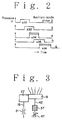
- FIG. 3 A modified embodiment of the invention is illustrated in FIG. 3, wherein the bypass line, e.g. 42, has an adjustable throttle valve 47 to make possible adjustment of the acceleration which may be required when any different kind of weft is to be handled.
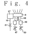
- FIG. 4 shows a further modified embodiment of the invention which differs from that shown in FIG. 3 in that a second bypass line 48 is added.
- at least one of the bypass lines 42, 48 has an adjustable throttle valve 47 or 50 which may be adjusted to allow less air flow therethrough than the fixed throttle valve 21 in the main line 16.
- the bypass line having the adjustable throttle valve may be used for decelerating the weft flying speed with the solenoid-operated valve 27 in the main line 16 then closed.
- the other bypass line is used for the acceleration as described in the above.
- FIG. 1 in the arrangement of FIG.
- the throttle valve 50 may have very little restriction of air flow while the throttle valve 47 slight restriction so that two-step acceleration can be effected by firstly opening the valve 37 and then activating the valve 49 with the former valve 37 closed. It would be understood readily by those skilled in the art that this embodiment of FIG. 4 is applicable to alternate insertion of two different kinds of weft. That is, air through the bypass line 48 is used for the acceleration and the valves 27 and 37 are opened alternately to supply air under different pressures for inserting different kinds of weft accordingly.
- provision of a line bypassing the main line between the air supply reservoir and the air distributor and having therein a controlled valve can dispense with a plurality of air reservoirs holding air under different pressures. Therefore, the construction of the apparatus can be simplified and requires smaller space for the installation. Additionally, the apparatus of the invention is applicable to insertion of different kinds of weft.
- weft detectors 32-36 provided in a warp shed may be substituted for other means adapted to detect the leading end of an inserted weft, e.g. a combination of a balloon sensor which is located adjacent a drum type weft measuring device disposed upstream of the main weft inserting nozzle for detecting the balloon in weft releasing from the device and a device which is adapted to figure out the current position of the inserted weft leading end on the basis of weft release signals provided by the balloon sensor.
- the apparatus is adapted for use in a jet loom and has at least one weft detector 32-36, a plurality of auxiliary nozzles 2a-2e, 3a-3e, 4a-4e. 5a-5e, 6a-6e, a fluid supply reservoir 13 from which fluid under pressure is supplied to each of the auxiliary nozzles 2a-2e, 3a-3e, 4a-4e.
- conduit lines 16-20 each having a first electromagnetically-operated valves 27-31, and a controller 26 for controlling the operation of the valves 27-31
- the apparatus includes a second electromagnetically-operated valve 37-41 provided in a bypass line 42-46 bypassing the main line and the operation of the second valve 37-41 is controlled by the controller 26 according to the information of time at which the leading end of each inserted weft Y has arrived at a predetermined position along weft flying passage in a warp shed of the loom.
- Apparatus for controlling fluid injection pressure of an auxiliary nozzle in a jet loom can be constructed simple and is advantageous in space factor by provision of a line bypassing the main line connected between the air supply reservoir and an auxiliary nozzle, and having therein an electromagnetically-controlled valve whose operation may be controlled by a controller for each weft insertion.
Landscapes
- Engineering & Computer Science (AREA)
- Textile Engineering (AREA)
- Looms (AREA)
Claims (7)
- Appareil pour commander la pression d'injection de fluide d'une buse auxiliaire (2a-2e, 3a-3e, 4a-4e, 5a-5e, 6a-6e) et l'insertion d'une trame (Y) dans un métier à jet, et pour commander l'insertion d'une trame (Y) pendant le temps d'insertion de ladite trame (Y), ledit appareil comportantau moins un détecteur de trame (32, 33, 34, 35, 36) qui est placé le long du passage de vol de la trame dans une foule du métier,plusieurs buses auxiliaires (2a-2e, 3a-3e, 4a-4e, 5a-5e, 6a-6e),un réservoir d'amenée de fluide sous pression, etdes conduits principaux (16, 17, 18, 19, 20) du réservoir d'amenée de fluide à chaque buse auxiliaire (2a-2e, 3a-3e, 4a-4e, 5a-5e, 6a-6e) ou groupe de buses auxiliaires (2a-2e, 3a-3e, 4a-4e, 5a-5e, 6a-6e) pour fournir du fluide sous pression auxdites buses auxiliaires (2a-2e, 3a-3e, 4a-4e, 5a-5e, 6a-6e),chaque conduit principal incluant une première vanne actionnée électromagnétiquement (27, 28, 29, 30, 31),un dispositif de commande (26) pour commander le fonctionnement desdites premières vannes actionnées électromagnétiquement (27, 28, 29, 30, 31),caractérisé parun réservoir d'amenée de fluide commun (13) et des conduits d'amenée (16, 17, 18, 19, 20) pour fournir du fluide sous pression dudit réservoir d'amenée (13) auxdites buses auxiliaires (2a-2e, 3a-3e, 4a-4e, 5a-5e, 6a-6e) ou groupes de buses auxiliaires (2a-2e, 3a-3e, 4a-4e, 5a-5e, 6a-6e),au moins plus d'un desdits conduits principaux (16, 17, 18, 19, 20) incluant un papillon (21, 22, 23, 24, 25),un conduit en dérivation (42, 43, 44, 45, 46) incluant une deuxième vanne actionnée électromagnetiquement (37, 38, 39, 40, 41) contournant lesdits papillons (21, 22, 23, 24, 25) et lesdites premières vannes actionnées électromagnétiquement dans au moins plus d'un conduit principal précité (16, 17, 18, 19, 20),un dispositif de commande (26) pour comparer l'instant où chaque trame insérée (Y) arrive à la position prédéterminée dudit détecteur de trame (32, 33, 34, 35, 36) avec l'instant de référence prédéterminé pour le passage à cette position prédéterminée, ledit dispositif de commande (26) faisant fonctionner ladite deuxième vanne (37, 38, 39, 40, 41) conformément au résultat de ladite comparaison et pendant le temps d'insertion de ladite trame (Y).
- Appareil selon la revendication 1, dans lequel plusieurs détecteurs de trame (32-36) sont placés le long du passage de vol de trame dans une foule du métier.
- Appareil selon la revendication 1 ou 2, dans lequel un conduit en dérivation (42-46) pour chaque conduit principal (16, 17, 18, 19, 20) est relié à une buse auxiliaire (2a-2e, 3a-3e, 4a-4e, 5a-5e, 6a-6e) où un groupe de buses auxiliaires (2a-2e, 3a-3e, 4a-4e, 5a-5e, 6a-6e).
- Appareil selon l'une des revendications 1 à 3, dans lequel des lignes de conduit de fluide (16-20) et des conduits en dérivation (42-46) ainsi qu'un groupe de buses auxiliaires sont reliées à au moins un distributeur de fluide (8-12).
- Appareil selon l'une des revendications 1 à 4, pour un métier à jet d'air avec des buses de jet d'air auxiliaires.
- Métier à jet de fluide avec un appareil selon l'une des revendications 1 à 5.
- Métier à jet d'air avec un appareil selon l'une des revendications 1 à 5.
Applications Claiming Priority (2)
| Application Number | Priority Date | Filing Date | Title |
|---|---|---|---|
| JP1198292A JPH05230739A (ja) | 1992-01-27 | 1992-01-27 | ジェットルームにおけるサブノズルの噴射圧制御装置 |
| JP11982/92 | 1992-01-27 |
Publications (2)
| Publication Number | Publication Date |
|---|---|
| EP0554221A1 EP0554221A1 (fr) | 1993-08-04 |
| EP0554221B1 true EP0554221B1 (fr) | 1997-06-11 |
Family
ID=11792809
Family Applications (1)
| Application Number | Title | Priority Date | Filing Date |
|---|---|---|---|
| EP19930810047 Expired - Lifetime EP0554221B1 (fr) | 1992-01-27 | 1993-01-26 | Appareil pour contrÔler la pression d'injection d'un fluide dans une buse auxiliaire d'un métier à jet |
Country Status (3)
| Country | Link |
|---|---|
| EP (1) | EP0554221B1 (fr) |
| JP (1) | JPH05230739A (fr) |
| DE (1) | DE69311386T2 (fr) |
Families Citing this family (6)
| Publication number | Priority date | Publication date | Assignee | Title |
|---|---|---|---|---|
| DE19602513C1 (de) * | 1996-01-25 | 1996-10-02 | Dornier Gmbh Lindauer | Verfahren zum Überwachen der Funktionstüchtigkeit elektrisch ansteuerbarer Magnetventile in Webmaschinen |
| JPH09228192A (ja) * | 1996-02-14 | 1997-09-02 | Tsudakoma Corp | よこ入れ制御方法 |
| DE19824613A1 (de) | 1998-06-02 | 1999-12-09 | Dornier Gmbh Lindauer | Verfahren zum Überwachen des Schußfadenfreigabe- und Stoppvorganges an Vorspulgeräten für Webmaschinen |
| JP2002105801A (ja) * | 2000-10-02 | 2002-04-10 | Toyota Industries Corp | エアジェット織機における圧縮空気供給装置 |
| JP5493639B2 (ja) * | 2009-09-23 | 2014-05-14 | 株式会社豊田自動織機 | エアジェットルームにおける緯入れ装置 |
| CN103114369A (zh) * | 2013-01-29 | 2013-05-22 | 青岛铠硕纺机有限公司 | 用于喷气织机的独立供气电子引纬系统 |
Family Cites Families (4)
| Publication number | Priority date | Publication date | Assignee | Title |
|---|---|---|---|---|
| CH647017A5 (de) * | 1980-10-22 | 1984-12-28 | Rueti Ag Maschf | Luftversorgungssystem fuer eine pneumatische webmaschine. |
| NL8600713A (nl) * | 1986-03-20 | 1987-10-16 | Picanol Nv | Werkwijze voor de sturing van bijblazers bij het inbrengen van een inslagdraad, bij weefmachines; en inrichting hiertoe aangewend. |
| JP2522245B2 (ja) * | 1986-05-01 | 1996-08-07 | 株式会社豊田自動織機製作所 | ジェットル―ムにおける緯入れ方法 |
| IT1250918B (it) * | 1990-06-27 | 1995-04-21 | Vamatex Spa | Sistema di controllo dell'alimentazione degli ugelli di trasporto della trama nel passo di telai a getto di fluido |
-
1992
- 1992-01-27 JP JP1198292A patent/JPH05230739A/ja active Pending
-
1993
- 1993-01-26 EP EP19930810047 patent/EP0554221B1/fr not_active Expired - Lifetime
- 1993-01-26 DE DE1993611386 patent/DE69311386T2/de not_active Expired - Fee Related
Also Published As
| Publication number | Publication date |
|---|---|
| EP0554221A1 (fr) | 1993-08-04 |
| JPH05230739A (ja) | 1993-09-07 |
| DE69311386D1 (de) | 1997-07-17 |
| DE69311386T2 (de) | 1997-11-20 |
Similar Documents
| Publication | Publication Date | Title |
|---|---|---|
| EP0554222B1 (fr) | Procédé pour contrÔler l'insertion de trame dans un métier à jet | |
| SU1056913A3 (ru) | Устройство дл регулировани скорости прокладывани уточной нити на ткацком станке | |
| KR870002026Y1 (ko) | 다색(多色) 에어제트(airjet) 직기의 위입(緯入) 장치 | |
| EP0554221B1 (fr) | Appareil pour contrÔler la pression d'injection d'un fluide dans une buse auxiliaire d'un métier à jet | |
| EP0105561B1 (fr) | Procédé pour le transport d'un fil de trame à travers la foule au moyen d'un fluide, ainsi qu'un métier à tisser équipé pour appliquer ce procédé | |
| EP3144422B1 (fr) | Procédé de surveillance de l'état de déplacement de trame dans un métier à tisser à jet d'air | |
| CN101445990A (zh) | 喷气织机纬纱飞行张力和飞行时间控制装置及其控制方法 | |
| US5295515A (en) | Apparatus for controlling weft insertion in jet loom | |
| US6748981B2 (en) | Air supply controller for weft insertion nozzles in an air jet loom | |
| JP2009068160A (ja) | 織機の圧力調節方法及び圧力調節システムを有する織機 | |
| CN101315564A (zh) | 喷气织机上喷射系统供气流量控制装置及其控制方法 | |
| EP1731645A2 (fr) | Dispositif d'alimentation et de régulation d'air pour le transport pneumatique de la trame dans un métier à tisser à jet d'air | |
| US6439271B2 (en) | Jet loom and method for achieving substantially identical weaving cycle times | |
| JP2618376B2 (ja) | ジエツトルームにおける緯入れ方法 | |
| JPH0258379B2 (fr) | ||
| JPH0235830Y2 (fr) | ||
| JPH01168941A (ja) | 水噴射式織機の複数緯糸選択緯入れ装置 | |
| JPH0140132B2 (fr) | ||
| US3842746A (en) | Proportional thrust control for levitated vehicles | |
| JPS62257441A (ja) | ジェットルームにおける緯入れ方法 | |
| JP2002088617A (ja) | 流体噴射式織機の緯入れ制御装置 | |
| JPH057269Y2 (fr) | ||
| JP2527726Y2 (ja) | 多色ジェットルームにおけるエア配管構造 | |
| CN102691157A (zh) | 带气流加速器的辅助喷嘴供气系统 | |
| JPH0336546Y2 (fr) |
Legal Events
| Date | Code | Title | Description |
|---|---|---|---|
| PUAI | Public reference made under article 153(3) epc to a published international application that has entered the european phase |
Free format text: ORIGINAL CODE: 0009012 |
|
| AK | Designated contracting states |
Kind code of ref document: A1 Designated state(s): BE DE FR IT |
|
| 17P | Request for examination filed |
Effective date: 19940128 |
|
| ITF | It: translation for a ep patent filed | ||
| 17Q | First examination report despatched |
Effective date: 19941107 |
|
| GRAG | Despatch of communication of intention to grant |
Free format text: ORIGINAL CODE: EPIDOS AGRA |
|
| GRAH | Despatch of communication of intention to grant a patent |
Free format text: ORIGINAL CODE: EPIDOS IGRA |
|
| GRAH | Despatch of communication of intention to grant a patent |
Free format text: ORIGINAL CODE: EPIDOS IGRA |
|
| GRAA | (expected) grant |
Free format text: ORIGINAL CODE: 0009210 |
|
| AK | Designated contracting states |
Kind code of ref document: B1 Designated state(s): BE DE FR IT |
|
| REF | Corresponds to: |
Ref document number: 69311386 Country of ref document: DE Date of ref document: 19970717 |
|
| ET | Fr: translation filed | ||
| PGFP | Annual fee paid to national office [announced via postgrant information from national office to epo] |
Ref country code: DE Payment date: 19980107 Year of fee payment: 6 |
|
| PLBE | No opposition filed within time limit |
Free format text: ORIGINAL CODE: 0009261 |
|
| STAA | Information on the status of an ep patent application or granted ep patent |
Free format text: STATUS: NO OPPOSITION FILED WITHIN TIME LIMIT |
|
| 26N | No opposition filed | ||
| PG25 | Lapsed in a contracting state [announced via postgrant information from national office to epo] |
Ref country code: DE Free format text: LAPSE BECAUSE OF NON-PAYMENT OF DUE FEES Effective date: 19991103 |
|
| PGFP | Annual fee paid to national office [announced via postgrant information from national office to epo] |
Ref country code: FR Payment date: 20010103 Year of fee payment: 9 |
|
| PGFP | Annual fee paid to national office [announced via postgrant information from national office to epo] |
Ref country code: BE Payment date: 20010118 Year of fee payment: 9 |
|
| PG25 | Lapsed in a contracting state [announced via postgrant information from national office to epo] |
Ref country code: BE Free format text: LAPSE BECAUSE OF NON-PAYMENT OF DUE FEES Effective date: 20020131 |
|
| BERE | Be: lapsed |
Owner name: TOYODA JIDOSHOKKI SEISAKUSHO K.K. Effective date: 20020131 |
|
| PG25 | Lapsed in a contracting state [announced via postgrant information from national office to epo] |
Ref country code: FR Free format text: LAPSE BECAUSE OF NON-PAYMENT OF DUE FEES Effective date: 20020930 |
|
| REG | Reference to a national code |
Ref country code: FR Ref legal event code: ST |
|
| PG25 | Lapsed in a contracting state [announced via postgrant information from national office to epo] |
Ref country code: IT Free format text: LAPSE BECAUSE OF NON-PAYMENT OF DUE FEES;WARNING: LAPSES OF ITALIAN PATENTS WITH EFFECTIVE DATE BEFORE 2007 MAY HAVE OCCURRED AT ANY TIME BEFORE 2007. THE CORRECT EFFECTIVE DATE MAY BE DIFFERENT FROM THE ONE RECORDED. Effective date: 20050126 |