EP0554235A1 - Moteur à combustion interne à deux temps avec au moins une soupape d'admission et une soupape d'échappement pour un cylindre - Google Patents
Moteur à combustion interne à deux temps avec au moins une soupape d'admission et une soupape d'échappement pour un cylindre Download PDFInfo
- Publication number
- EP0554235A1 EP0554235A1 EP93890002A EP93890002A EP0554235A1 EP 0554235 A1 EP0554235 A1 EP 0554235A1 EP 93890002 A EP93890002 A EP 93890002A EP 93890002 A EP93890002 A EP 93890002A EP 0554235 A1 EP0554235 A1 EP 0554235A1
- Authority
- EP
- European Patent Office
- Prior art keywords
- inlet
- seat ring
- inlet channel
- valve seat
- valve
- Prior art date
- Legal status (The legal status is an assumption and is not a legal conclusion. Google has not performed a legal analysis and makes no representation as to the accuracy of the status listed.)
- Withdrawn
Links
- 238000002485 combustion reaction Methods 0.000 claims description 18
- 238000010926 purge Methods 0.000 claims description 4
- 230000007704 transition Effects 0.000 claims description 2
- 230000002000 scavenging effect Effects 0.000 abstract 2
- 239000007789 gas Substances 0.000 description 11
- 230000002349 favourable effect Effects 0.000 description 2
- 238000000034 method Methods 0.000 description 2
- 230000004888 barrier function Effects 0.000 description 1
- 238000011010 flushing procedure Methods 0.000 description 1
- 239000000446 fuel Substances 0.000 description 1
Images
Classifications
-
- F—MECHANICAL ENGINEERING; LIGHTING; HEATING; WEAPONS; BLASTING
- F02—COMBUSTION ENGINES; HOT-GAS OR COMBUSTION-PRODUCT ENGINE PLANTS
- F02B—INTERNAL-COMBUSTION PISTON ENGINES; COMBUSTION ENGINES IN GENERAL
- F02B25/00—Engines characterised by using fresh charge for scavenging cylinders
- F02B25/14—Engines characterised by using fresh charge for scavenging cylinders using reverse-flow scavenging, e.g. with both outlet and inlet ports arranged near bottom of piston stroke
- F02B25/145—Engines characterised by using fresh charge for scavenging cylinders using reverse-flow scavenging, e.g. with both outlet and inlet ports arranged near bottom of piston stroke with intake and exhaust valves exclusively in the cylinder head
-
- F—MECHANICAL ENGINEERING; LIGHTING; HEATING; WEAPONS; BLASTING
- F02—COMBUSTION ENGINES; HOT-GAS OR COMBUSTION-PRODUCT ENGINE PLANTS
- F02B—INTERNAL-COMBUSTION PISTON ENGINES; COMBUSTION ENGINES IN GENERAL
- F02B27/00—Use of kinetic or wave energy of charge in induction systems, or of combustion residues in exhaust systems, for improving quantity of charge or for increasing removal of combustion residues
- F02B27/02—Use of kinetic or wave energy of charge in induction systems, or of combustion residues in exhaust systems, for improving quantity of charge or for increasing removal of combustion residues the systems having variable, i.e. adjustable, cross-sectional areas, chambers of variable volume, or like variable means
- F02B27/0226—Use of kinetic or wave energy of charge in induction systems, or of combustion residues in exhaust systems, for improving quantity of charge or for increasing removal of combustion residues the systems having variable, i.e. adjustable, cross-sectional areas, chambers of variable volume, or like variable means characterised by the means generating the charging effect
- F02B27/0289—Intake runners having multiple intake valves per cylinder
-
- F—MECHANICAL ENGINEERING; LIGHTING; HEATING; WEAPONS; BLASTING
- F02—COMBUSTION ENGINES; HOT-GAS OR COMBUSTION-PRODUCT ENGINE PLANTS
- F02F—CYLINDERS, PISTONS OR CASINGS, FOR COMBUSTION ENGINES; ARRANGEMENTS OF SEALINGS IN COMBUSTION ENGINES
- F02F1/00—Cylinders; Cylinder heads
- F02F1/24—Cylinder heads
- F02F1/42—Shape or arrangement of intake or exhaust channels in cylinder heads
- F02F1/4214—Shape or arrangement of intake or exhaust channels in cylinder heads specially adapted for four or more valves per cylinder
-
- F—MECHANICAL ENGINEERING; LIGHTING; HEATING; WEAPONS; BLASTING
- F02—COMBUSTION ENGINES; HOT-GAS OR COMBUSTION-PRODUCT ENGINE PLANTS
- F02B—INTERNAL-COMBUSTION PISTON ENGINES; COMBUSTION ENGINES IN GENERAL
- F02B75/00—Other engines
- F02B75/02—Engines characterised by their cycles, e.g. six-stroke
- F02B2075/022—Engines characterised by their cycles, e.g. six-stroke having less than six strokes per cycle
- F02B2075/025—Engines characterised by their cycles, e.g. six-stroke having less than six strokes per cycle two
-
- F—MECHANICAL ENGINEERING; LIGHTING; HEATING; WEAPONS; BLASTING
- F02—COMBUSTION ENGINES; HOT-GAS OR COMBUSTION-PRODUCT ENGINE PLANTS
- F02F—CYLINDERS, PISTONS OR CASINGS, FOR COMBUSTION ENGINES; ARRANGEMENTS OF SEALINGS IN COMBUSTION ENGINES
- F02F1/00—Cylinders; Cylinder heads
- F02F1/02—Cylinders; Cylinder heads having cooling means
- F02F1/10—Cylinders; Cylinder heads having cooling means for liquid cooling
- F02F2001/104—Cylinders; Cylinder heads having cooling means for liquid cooling using an open deck, i.e. the water jacket is open at the block top face
-
- F—MECHANICAL ENGINEERING; LIGHTING; HEATING; WEAPONS; BLASTING
- F02—COMBUSTION ENGINES; HOT-GAS OR COMBUSTION-PRODUCT ENGINE PLANTS
- F02F—CYLINDERS, PISTONS OR CASINGS, FOR COMBUSTION ENGINES; ARRANGEMENTS OF SEALINGS IN COMBUSTION ENGINES
- F02F1/00—Cylinders; Cylinder heads
- F02F1/24—Cylinder heads
- F02F2001/244—Arrangement of valve stems in cylinder heads
- F02F2001/247—Arrangement of valve stems in cylinder heads the valve stems being orientated in parallel with the cylinder axis
-
- Y—GENERAL TAGGING OF NEW TECHNOLOGICAL DEVELOPMENTS; GENERAL TAGGING OF CROSS-SECTIONAL TECHNOLOGIES SPANNING OVER SEVERAL SECTIONS OF THE IPC; TECHNICAL SUBJECTS COVERED BY FORMER USPC CROSS-REFERENCE ART COLLECTIONS [XRACs] AND DIGESTS
- Y02—TECHNOLOGIES OR APPLICATIONS FOR MITIGATION OR ADAPTATION AGAINST CLIMATE CHANGE
- Y02T—CLIMATE CHANGE MITIGATION TECHNOLOGIES RELATED TO TRANSPORTATION
- Y02T10/00—Road transport of goods or passengers
- Y02T10/10—Internal combustion engine [ICE] based vehicles
- Y02T10/12—Improving ICE efficiencies
Definitions
- the invention relates to a two-stroke internal combustion engine with at least one inlet and exhaust valve per cylinder arranged parallel to the cylinder axis, with the associated intake and exhaust ports in the cylinder head and combustion chamber purging by supplying fresh gas, the flow of the intake port being generated in the combustion chamber by the shape of the intake port and the entry channel has areas of different entry angles.
- Such fuel engines are interested in minimizing the short-circuit losses that occur during the covering phase of the opening times of intake and exhaust valves due to purging processes, that is to say losses due to the escape of fresh gas via the shortest route through the exhaust valve.
- the fresh gas entering this phase should only leave the combustion chamber when it is burned when the exhaust gases are expelled.
- the object of the invention is to avoid these disadvantages and to provide a two-stroke internal combustion engine in which, on the one hand, the fresh gas losses during the flushing process are minimized and, on the other hand, the flow losses are reduced.
- the inlet angle of the inlet channel in a region facing the inlet-side boundary plane of the valve seat ring the surface of the inlet channel is larger in a manner known per se than the inlet angle of the inlet channel in a region of the surface of the inlet channel facing away from the inlet-side boundary plane of the valve seat ring, both angles measured in the valve seat ring as the angle between the inlet-side boundary plane of the valve seat ring and the tangent to the surface of the Inlet channel, wherein the main flow direction of the fresh gas is directed towards the cylinder wall and away from the engine longitudinal plane.
- the area of the surface facing the inlet-side boundary plane of the valve seat ring is to be understood as that surface segment of the inlet duct whose surface normals still intersect the boundary plane within the cavity formed by the inlet duct walls.
- the area of the surface of the inlet channel facing away is accordingly the surface segment whose surface normals intersect the boundary plane on the inlet side outside the cavity.
- speed components directed towards the cylinder wall and piston are thus generated solely by designing an aerodynamically favorable entry region of the fresh gas.
- a large part of the fresh gas entering the combustion chamber during the purging phase thereby flows along the cylinder wall in the direction of the piston, short-circuit losses being largely avoided and additional losses caused by the deflection of the flow remaining minimal.
- the inlet angle of the inlet channel in the region of the surface of the inlet channel in which it faces away from the valve seat ring is between 20 ° and 45 °, preferably 30 °, and the inlet angle of the inlet channel in the region of the surface of the inlet channel , in which this faces the valve seat ring of the inlet valve, is between 50 ° and 70 °, preferably at 60 °.
- the transition of the surface of the inlet channel preferably runs continuously in each area.
- the regions of the surfaces of the intake ducts are arranged symmetrically with respect to the plane of symmetry, which runs between the intake valves at right angles to the longitudinal axis of the engine.
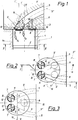
- the internal combustion engine comprises a cylinder block 1, a reciprocating piston 2, a cylinder head 3 attached to the cylinder block 1, and a combustion chamber 4 formed between the inner wall of the cylinder 1a and the bottom of the piston 2
- the intake ports 5 and the exhaust port 6 contained in the cylinder head 3 are constructed so that the flanges are on the same side of the cylinder head. If a plurality of intake valves 7 or exhaust valves 8 are present, these are arranged such that the connecting straight lines of the valve centers of the intake valves 7 or the connecting straight lines of the valve centers of the exhaust valves 8 are preferably parallel to the engine longitudinal axis X.
- the entry angle of the inlet channel 5 in the area B is marked with ß.
- the direction of flow and the amount of fresh gas entering is indicated by the direction and length of the arrows S1 and S2 in Fig. 1.
- Both the area A and the area B extend over an angle 11 or 12 of approximately 90 ° to 160 °, wherein the areas A and B can also be of different sizes. 15 with a normal to the longitudinal plane 16 of the plane of symmetry is designated.
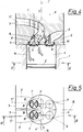
- the invention is particularly suitable for a wide variety of arrangements and numbers of intake and exhaust valves 9 and 10, respectively.
- the embodiment according to FIG. 3 has two inlet valves 7 and only one outlet valve 8.
- the flanges of the intake ports 5 and the exhaust port 6 are arranged on opposite sides of the cylinder head 3.
- the requirements as in the embodiment according to FIGS. 1 and 2 also apply here; there are similar flow conditions.
Landscapes
- Engineering & Computer Science (AREA)
- Chemical & Material Sciences (AREA)
- Combustion & Propulsion (AREA)
- Mechanical Engineering (AREA)
- General Engineering & Computer Science (AREA)
- Cylinder Crankcases Of Internal Combustion Engines (AREA)
Applications Claiming Priority (2)
| Application Number | Priority Date | Filing Date | Title |
|---|---|---|---|
| AT14692 | 1992-01-29 | ||
| AT146/92 | 1992-01-29 |
Publications (1)
| Publication Number | Publication Date |
|---|---|
| EP0554235A1 true EP0554235A1 (fr) | 1993-08-04 |
Family
ID=3482753
Family Applications (1)
| Application Number | Title | Priority Date | Filing Date |
|---|---|---|---|
| EP93890002A Withdrawn EP0554235A1 (fr) | 1992-01-29 | 1993-01-11 | Moteur à combustion interne à deux temps avec au moins une soupape d'admission et une soupape d'échappement pour un cylindre |
Country Status (1)
| Country | Link |
|---|---|
| EP (1) | EP0554235A1 (fr) |
Cited By (8)
| Publication number | Priority date | Publication date | Assignee | Title |
|---|---|---|---|---|
| WO1995016113A1 (fr) * | 1993-12-08 | 1995-06-15 | Koenig Kurt | Moteur commande a combustion interne a deux temps |
| EP0924422A3 (fr) * | 1997-12-18 | 2000-02-23 | Nissan Motor Company, Limited | Moteur à combustion interne avec allumage par étincelle et injection directe |
| EP0984149A3 (fr) * | 1998-08-31 | 2001-01-24 | Honda Giken Kogyo Kabushiki Kaisha | Structure d'une culasse pour un moteur à combustion interne |
| US6401702B1 (en) | 1993-12-08 | 2002-06-11 | Koenig Kurt | Controlled two-stroke internal combustion engine |
| US6880509B2 (en) | 2002-08-23 | 2005-04-19 | Avl List Gmbh | Intake manifolding for an internal combustion engine |
| AT413856B (de) * | 2002-08-23 | 2006-06-15 | Avl List Gmbh | Einlasskanalanordnung |
| WO2022183868A1 (fr) * | 2021-03-01 | 2022-09-09 | 比亚迪股份有限公司 | Moteur et véhicule à moteur |
| CN117569942A (zh) * | 2024-01-17 | 2024-02-20 | 潍柴动力股份有限公司 | 一种发动机缸盖以及发动机 |
Citations (3)
| Publication number | Priority date | Publication date | Assignee | Title |
|---|---|---|---|---|
| CH377584A (de) * | 1958-03-25 | 1964-05-15 | Tatra Np | Saugkanal in einem Verbrennungsmotor, insbesondere Dieselmotor |
| EP0431866A1 (fr) * | 1989-12-07 | 1991-06-12 | Ricardo Group Plc | Moteur à combustion interne |
| EP0432950A1 (fr) * | 1989-12-15 | 1991-06-19 | Ricardo Group Plc | Moteur à combustion interne |
-
1993
- 1993-01-11 EP EP93890002A patent/EP0554235A1/fr not_active Withdrawn
Patent Citations (3)
| Publication number | Priority date | Publication date | Assignee | Title |
|---|---|---|---|---|
| CH377584A (de) * | 1958-03-25 | 1964-05-15 | Tatra Np | Saugkanal in einem Verbrennungsmotor, insbesondere Dieselmotor |
| EP0431866A1 (fr) * | 1989-12-07 | 1991-06-12 | Ricardo Group Plc | Moteur à combustion interne |
| EP0432950A1 (fr) * | 1989-12-15 | 1991-06-19 | Ricardo Group Plc | Moteur à combustion interne |
Cited By (13)
| Publication number | Priority date | Publication date | Assignee | Title |
|---|---|---|---|---|
| WO1995016113A1 (fr) * | 1993-12-08 | 1995-06-15 | Koenig Kurt | Moteur commande a combustion interne a deux temps |
| US5738050A (en) * | 1993-12-08 | 1998-04-14 | Koenig; Kurt | Controlled two-stroke internal combustion engine |
| US6401702B1 (en) | 1993-12-08 | 2002-06-11 | Koenig Kurt | Controlled two-stroke internal combustion engine |
| EP0924422A3 (fr) * | 1997-12-18 | 2000-02-23 | Nissan Motor Company, Limited | Moteur à combustion interne avec allumage par étincelle et injection directe |
| US6196185B1 (en) | 1997-12-18 | 2001-03-06 | Nissan Motor Co., Ltd. | Fuel direct injection spark ignition type internal combustion engine |
| EP0984149A3 (fr) * | 1998-08-31 | 2001-01-24 | Honda Giken Kogyo Kabushiki Kaisha | Structure d'une culasse pour un moteur à combustion interne |
| US6880509B2 (en) | 2002-08-23 | 2005-04-19 | Avl List Gmbh | Intake manifolding for an internal combustion engine |
| DE10338132B4 (de) * | 2002-08-23 | 2005-11-10 | Avl List Gmbh | Einlasskanalanordnung für eine Brennkraftmaschine |
| AT413856B (de) * | 2002-08-23 | 2006-06-15 | Avl List Gmbh | Einlasskanalanordnung |
| WO2022183868A1 (fr) * | 2021-03-01 | 2022-09-09 | 比亚迪股份有限公司 | Moteur et véhicule à moteur |
| US11952957B2 (en) | 2021-03-01 | 2024-04-09 | Byd Company Limited | Engine and vehicle having the same |
| CN117569942A (zh) * | 2024-01-17 | 2024-02-20 | 潍柴动力股份有限公司 | 一种发动机缸盖以及发动机 |
| CN117569942B (zh) * | 2024-01-17 | 2024-04-16 | 潍柴动力股份有限公司 | 一种发动机缸盖以及发动机 |
Similar Documents
| Publication | Publication Date | Title |
|---|---|---|
| DE3625947C2 (de) | Brennkraftmaschinen-Zylinderkopf mit Kühlmittelkanälen | |
| DE4410686A1 (de) | Ansaugsystem für Verbrennungsmotor | |
| DE19942169C2 (de) | Brennkraftmaschine mit zwei Einlassventilen je Zylinder | |
| EP0554235A1 (fr) | Moteur à combustion interne à deux temps avec au moins une soupape d'admission et une soupape d'échappement pour un cylindre | |
| DE4409750B4 (de) | Zylinderblock einer flüssigkeitsgekühlten Brennkraftmaschine mit einem Magnesium-Gehäuse | |
| EP0819837B1 (fr) | Circuit de refroidissement d'un moteur à combustion interne | |
| DE3107898A1 (de) | "querstrom-verbrennungsmotor mit abgas-rueckfuehrungsanlage" | |
| EP0204687B1 (fr) | Moteur à combustion interne à deux temps | |
| EP0878618A2 (fr) | Bloc cylindres refroidi par eau | |
| DE3806031C2 (de) | Mehrzylindermotorblock für einen Zweitaktverbrennungsmotor | |
| DE2946017A1 (de) | Auspuffkanal fuer verbrennungsmotor | |
| DE3435386A1 (de) | Luftgekuehlte mehrzylinder-brennkraftmaschine | |
| DE69419913T2 (de) | Induktionssystem einer internen brennkraftmaschine | |
| DE69806644T2 (de) | Zylinderkopf für eine verbrennungskraftmaschine | |
| EP0855502A2 (fr) | Moteur à combustion interne avec système de recirculation de gaz d'échappement | |
| DE3909544C2 (fr) | ||
| DE19949616A1 (de) | Ansaugsystem für einen Zylinderkopf | |
| EP0123101B1 (fr) | Culasse pour moteur à combustion interne alternatif à refroissement par air | |
| DE3137453A1 (de) | Ansauganordnung fuer eine brennkraftmaschine | |
| DE4012492A1 (de) | Zweitakt-hubkolben-brennkraftmaschine mit ladungswechselventilen und umkehrspuelung | |
| DE814685C (de) | Kuehlmittelfuehrung bei fluessigkeitsgekuehlten Verbrennungsmotoren | |
| DE19740229B4 (de) | Brennkraftmaschinen-Zylinderkopf mit Ansaugkanal und Zusatzluftkanal | |
| EP0598699A1 (fr) | Moteur à combustion interne à quatre temps | |
| DE2319662C3 (de) | Zylinder für Zweitakt-Hubkolben- Brennkraftmaschinen | |
| AT402538B (de) | Zylinderkopf für einen teilweise flüssigkeitsgekühlten dieselmotor |
Legal Events
| Date | Code | Title | Description |
|---|---|---|---|
| PUAI | Public reference made under article 153(3) epc to a published international application that has entered the european phase |
Free format text: ORIGINAL CODE: 0009012 |
|
| 17P | Request for examination filed |
Effective date: 19930518 |
|
| AK | Designated contracting states |
Kind code of ref document: A1 Designated state(s): DE ES FR GB IT SE |
|
| 17Q | First examination report despatched |
Effective date: 19940209 |
|
| STAA | Information on the status of an ep patent application or granted ep patent |
Free format text: STATUS: THE APPLICATION HAS BEEN WITHDRAWN |
|
| 18W | Application withdrawn |
Withdrawal date: 19940824 |