EP0432950A1 - Moteur à combustion interne - Google Patents
Moteur à combustion interne Download PDFInfo
- Publication number
- EP0432950A1 EP0432950A1 EP90313094A EP90313094A EP0432950A1 EP 0432950 A1 EP0432950 A1 EP 0432950A1 EP 90313094 A EP90313094 A EP 90313094A EP 90313094 A EP90313094 A EP 90313094A EP 0432950 A1 EP0432950 A1 EP 0432950A1
- Authority
- EP
- European Patent Office
- Prior art keywords
- cylinder
- inlet
- axis
- engine
- ports
- Prior art date
- Legal status (The legal status is an assumption and is not a legal conclusion. Google has not performed a legal analysis and makes no representation as to the accuracy of the status listed.)
- Granted
Links
Images

Classifications
-
- F—MECHANICAL ENGINEERING; LIGHTING; HEATING; WEAPONS; BLASTING
- F02—COMBUSTION ENGINES; HOT-GAS OR COMBUSTION-PRODUCT ENGINE PLANTS
- F02B—INTERNAL-COMBUSTION PISTON ENGINES; COMBUSTION ENGINES IN GENERAL
- F02B31/00—Modifying induction systems for imparting a rotation to the charge in the cylinder
-
- F—MECHANICAL ENGINEERING; LIGHTING; HEATING; WEAPONS; BLASTING
- F02—COMBUSTION ENGINES; HOT-GAS OR COMBUSTION-PRODUCT ENGINE PLANTS
- F02F—CYLINDERS, PISTONS OR CASINGS, FOR COMBUSTION ENGINES; ARRANGEMENTS OF SEALINGS IN COMBUSTION ENGINES
- F02F1/00—Cylinders; Cylinder heads
- F02F1/24—Cylinder heads
- F02F1/42—Shape or arrangement of intake or exhaust channels in cylinder heads
- F02F1/4214—Shape or arrangement of intake or exhaust channels in cylinder heads specially adapted for four or more valves per cylinder
-
- F—MECHANICAL ENGINEERING; LIGHTING; HEATING; WEAPONS; BLASTING
- F02—COMBUSTION ENGINES; HOT-GAS OR COMBUSTION-PRODUCT ENGINE PLANTS
- F02B—INTERNAL-COMBUSTION PISTON ENGINES; COMBUSTION ENGINES IN GENERAL
- F02B25/00—Engines characterised by using fresh charge for scavenging cylinders
- F02B25/14—Engines characterised by using fresh charge for scavenging cylinders using reverse-flow scavenging, e.g. with both outlet and inlet ports arranged near bottom of piston stroke
- F02B25/145—Engines characterised by using fresh charge for scavenging cylinders using reverse-flow scavenging, e.g. with both outlet and inlet ports arranged near bottom of piston stroke with intake and exhaust valves exclusively in the cylinder head
-
- F—MECHANICAL ENGINEERING; LIGHTING; HEATING; WEAPONS; BLASTING
- F02—COMBUSTION ENGINES; HOT-GAS OR COMBUSTION-PRODUCT ENGINE PLANTS
- F02B—INTERNAL-COMBUSTION PISTON ENGINES; COMBUSTION ENGINES IN GENERAL
- F02B1/00—Engines characterised by fuel-air mixture compression
- F02B1/02—Engines characterised by fuel-air mixture compression with positive ignition
- F02B1/04—Engines characterised by fuel-air mixture compression with positive ignition with fuel-air mixture admission into cylinder
-
- F—MECHANICAL ENGINEERING; LIGHTING; HEATING; WEAPONS; BLASTING
- F02—COMBUSTION ENGINES; HOT-GAS OR COMBUSTION-PRODUCT ENGINE PLANTS
- F02B—INTERNAL-COMBUSTION PISTON ENGINES; COMBUSTION ENGINES IN GENERAL
- F02B75/00—Other engines
- F02B75/02—Engines characterised by their cycles, e.g. six-stroke
- F02B2075/022—Engines characterised by their cycles, e.g. six-stroke having less than six strokes per cycle
- F02B2075/025—Engines characterised by their cycles, e.g. six-stroke having less than six strokes per cycle two
-
- F—MECHANICAL ENGINEERING; LIGHTING; HEATING; WEAPONS; BLASTING
- F02—COMBUSTION ENGINES; HOT-GAS OR COMBUSTION-PRODUCT ENGINE PLANTS
- F02B—INTERNAL-COMBUSTION PISTON ENGINES; COMBUSTION ENGINES IN GENERAL
- F02B3/00—Engines characterised by air compression and subsequent fuel addition
- F02B3/06—Engines characterised by air compression and subsequent fuel addition with compression ignition
-
- F—MECHANICAL ENGINEERING; LIGHTING; HEATING; WEAPONS; BLASTING
- F02—COMBUSTION ENGINES; HOT-GAS OR COMBUSTION-PRODUCT ENGINE PLANTS
- F02F—CYLINDERS, PISTONS OR CASINGS, FOR COMBUSTION ENGINES; ARRANGEMENTS OF SEALINGS IN COMBUSTION ENGINES
- F02F1/00—Cylinders; Cylinder heads
- F02F1/24—Cylinder heads
- F02F2001/244—Arrangement of valve stems in cylinder heads
- F02F2001/245—Arrangement of valve stems in cylinder heads the valve stems being orientated at an angle with the cylinder axis
-
- F—MECHANICAL ENGINEERING; LIGHTING; HEATING; WEAPONS; BLASTING
- F02—COMBUSTION ENGINES; HOT-GAS OR COMBUSTION-PRODUCT ENGINE PLANTS
- F02F—CYLINDERS, PISTONS OR CASINGS, FOR COMBUSTION ENGINES; ARRANGEMENTS OF SEALINGS IN COMBUSTION ENGINES
- F02F1/00—Cylinders; Cylinder heads
- F02F1/24—Cylinder heads
- F02F2001/244—Arrangement of valve stems in cylinder heads
- F02F2001/247—Arrangement of valve stems in cylinder heads the valve stems being orientated in parallel with the cylinder axis
Definitions
- the present invention relates to internal combustion engines and is concerned with spark ignited or compression ignited engines, preferably of two-stroke but also of four-stroke type, which include at least one cylinder, a piston reciprocable within the cylinder and a cylinder head which contains at least one exhaust port which is controlled by a poppet valve and at least two inlet ports controlled by respective poppet valves and connected to respective inlet ducts, the inlet ports being of directed type with the axes of the inlet ducts being convergent in the direction of flow whereby the air flowing through them into the cylinder flows preferentially in one radial direction relative to the associated valve axis generally towards the cylinder axis.
- Directed ports are that type of port in which the air flowing through it into the cylinder flows preferentially in one radial direction relative to the associated valve axis.
- Such ports communicate with an inlet duct which has a relatively abrupt bend shortly upstream of the port.
- the radius of the inside of the bend is typically less than 0.3r where r is the radius of the port, and is substantially less than the radius of the outside of the bend whereby, in use, the air flow breaks away from the inside of the bend and enters the cylinder preferentially in the direction determined by the inlet duct upstream of the bend, i.e. the direction is substantially unaffected by the bend.
- the air thus enters the cylinder predominantly on one side of the port with respect to the valve axis.
- An alternative method of generating turbulence around TDC is to induce "tumbling" motion of the air in the cylinder by constructing the inlet port(s) so that they produce rotation of the air in the cylinder about an axis which is transverse to the axis of the cylinder. Unlike swirl, which tends to continue in the cylinder beyond TDC, tumbling motion is wholly converted into turbulence at TDC. "Tumbling" motion is effective not only for producing turbulence in two-stroke and four-stroke engines but also for purging two-stroke engines.
- Known engines of this type include inlet ducts which are substantially parallel to the cylinder axis whereby air flowing in through the inlet ports flows predominantly down the adjacent side of the cylinder and is then caused to flow across the piston and up the other side of the cylinder, thereby creating a degree of tumbling motion.
- Such engines are described in GB-A-1568302 and EP-A-0299385.
- Two-stroke engines have a very limited time in which to complete the processes of exhausting the burnt gases and inletting the fresh charge of combustion air. Ideally, these processes are effected separately and consecutively. However, in practice there is insufficient time to do this. In all two-stroke engines the period for which the inlet valve is open therefore overlaps with that in which the exhaust valve is open. There is therefore a tendency for the incoming air to flow straight from the inlet valve to the exhaust valve without purging exhaust gases from the cylinder.
- the exhaust port may be controlled by a poppet valve and located in the cylinder head and the inlet ports are still controlled by the piston. Air flowing in through the inlet ports in the cylinder wall flows axially along the cylinder to purge it of exhaust gases via the exhaust valve.
- EP 0235121 on which the precharacterising portion of claim 1 is based, discloses an engine in which each cylinder has two inlet ports and a single exhaust port.
- the inlet ports direct the air preferentially towards the cylinder axis and the axes of the inlet ducts and thus of the inflowing air streams, are slightly convergent.
- These axes are relatively shallowly inclined, when viewed from the side, and, if projected in the direction of flow, would intersect at a distance of about 2.25R from the axis of the cylinder (where R is the radius of the cylinder) at a point which is not very significantly below the cylinder head.
- an engine of the type referred to above is characterised in that the axes of the inlet ducts pass substantially through the cylinder axis whereby the air flows through the inlet ports merge to form a single air flow on or adjacent the cylinder axis.
- the air flows from the inlet ports flow generally axially in the cylinder but biassed so as to flow out of the ports on the side closest the cylinder axis and towards the cylinder axis.
- the axis of each inlet duct thus has a substantial axial component, e.g. is inclined by 60°, more preferably 45°, or less to a line parallel to the cylinder axis, the line intersecting the axis of the inlet duct.
- the flows of inlet air merge into a single compact, vigorous air flow which flows towards the piston predominantly along or adjacent to the axis of the cylinder and thus if the engine is of two-stroke type the centre of the cylinder is effectively purged.
- the inflowing air is then deflected laterally by the piston and flows upwardly again and thus purges all the exhaust gases out through the exhaust valve(s) in the case of a two-stroke engine.
- the air motion is converted into intense turbulence at TDC and thus promotes effective combustion in both two-stroke and four-stroke engines.
- the invention is applicable not only to spark ignited engines but also to compression ignited engines, i.e. diesel engines.
- the convergency of the inlet air flows towards the cylinder axis is found to result not only in more effective purging of two-stroke engines but also in more intense turbulence in both two- and four-stroke engines. If there are only two inlet ports it is preferred that they converge at an angle of at least 40° but it will be appreciated that there may be more than two inlet ports and in this event it is preferred that the axes of the two outer inlet ducts are inclined by at least 40° whilst the axis of the duct or ducts between them is inclined to their ducts by a lesser angle.
- the ducts of the two outer ports will be inclined by 40° or more and the duct of the central port may for instance, extend vertically and thus be inclined to the ducts of the other ports by 20° or more.
- the axis of an inlet duct is the direction in which the major proportion of the length of the duct extends and thus the predominant direction of the momentum of the air flowing within the duct and it will be appreciated that if, as is usual, there is a bend in the inlet duct shortly before the inlet port, that is to say the inlet valve seat, the axis of the duct is coincident with the axis of the portion of the duct upstream of the bend.
- each inlet port is inclined away from the axis of the cylinder in the direction of flow and this means that the air flowing through each inlet port is predominantly directed away from the exhaust port whereby substantially no air can flow directly from the inlet ports into the exhaust port(s).
- the seat of each inlet valve is situated closer to the piston than the seat of the or each exhaust valve and this will inherently result in there being a projection or barrier between the inlet ports and the exhaust port(s) which acts as a further impediment to the direct flow of air from the inlet ports to the exhaust port(s).
- the engine has two substantially diametrically opposed inlet ports and two substantially diametrically opposed exhaust ports.
- the flows of air through the two inlet ports will merge into a single substantially axial column which flows towards the piston and is then deflected by the piston to flow laterally and then back towards the exhaust ports in the manner of an inverted fountain.
- the flow of air towards the piston effectively divides into two separate portions as it approaches the exhaust ports, which subsequently flow out through respective exhaust ports.
- the air motion in this embodiment can be thought of as "tumbling" motion but instead of the single loop or tumbling pattern which is induced in the prior specifications and referred to above there are two separate loops or tumbling patterns, each of which flows along the axis of the cylinder and is thus not concentrated at its outer edges and thereby effectively purges the entire volume of the cylinder.
- the axes of the inlet ducts may intersect at a point on the cylinder axis.
- the two inlet ports are slightly offset with respect to the associated diameter and more advantageous if the axes of the inlet ducts also extend on opposite sides of the cylinder axis, when viewed in the axial direction, and are spaced from it by a distance which does not exceed 0.15R, where R is the radius of the cylinder, whereby the air flows through the inlet ports merge to form a single air flow which rotates substantially about the cylinder axis.
- the engine comprises a cylinder block 2 defining one or more cylinders 4, in this case four cylinders, each of which contains a reciprocable piston 6.
- the cylinders 4 are closed by a common cylinder head 8 in which a single exhaust port 10, which communicates with an exhaust duct 16, and two adjacent inlet ports 12, which communicate with respective inlet ducts 14, are formed.
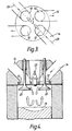
- the exhaust port 10 communicates with one half of the cylinder and the inlet ports 12 with the other half of the cylinder, when viewed in plan, as seen in Figure 2.
- the exhaust port 10 is controlled by an exhaust poppet valve 18 whose axis extends parallel to the axis of the cylinder and the inlet ports 12 are controlled by respective inlet poppet valves 20 whose axes are parallel and inclined towards the exhaust valve and subtend an acute angle of 10 to 40° to a line parallel to the cylinder axis.
- Each inlet duct comprises an initial short portion 22 immediately adjacent the associated inlet port 12, whose axis is coincident with that of the inlet port and extends, in the direction of flow, away from the cylinder axis, and a longer substantially straight portion 24 whose axis 23 is oppositely inclined to the cylinder axis.
- the intersection of the short and long portions 22 and 24 is such that the inner edge has a relatively small radius of curvature which does not exceed 0.3r, where r is the radius of the inlet port, i.e. the radius of the inlet valve seat.
- the axes 23 of the inlet ducts i.e. the axes of the major portions 24 of the inlet ducts, are convergent in the direction of flow and define an angle of 20 to 120°, preferably 40 to 90°, and pass through the cylinder axis 5.
- inlet ports 12 there are two diametrically opposed inlet ports 12 whose axes extend parallel to the cylinder axis and which are substantially equiangularly spaced, when viewed in plan, from two diametrically opposed exhaust ports 10.
- the axes of the inlet ducts pass through the cylinder axis 5.
- the air flows through the two inlet ports converge, when viewed in elevation, and merge to form a strong central stream of downwardly flowing air which purges the central portion of the cylinder and is then deflected by the piston crown and flows up the cylinder walls.
- the downward flow of air tends to divide the upward flow into two equal parts which flow separately into the exhaust ports.
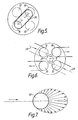
- the piston crown is in this case provided with an elongate, arcuate recess or trench 26, whose length is aligned with the diameter on which the exhaust ports lie, as seen in Figure 5.
- This trench forms a compact combustion chamber when the piston is at top dead centre and the surrounding areas serve to generate squish, whereby the piston approaches the cylinder head very closely at TDC and forces the gas transversely out of these areas into the trench thereby causing intense and beneficial turbulence in the combustion chamber which promotes rapid and complete combustion.
- the projection 21 is unnecessary and the fact that the axes of the inlet and exhaust ports parallel to the cylinder axis results in the piston being able to approach the cylinder head more closely and thus in a higher compression ratio.
- the spark plug 25 is again conveniently provided in the central region of the cylinder head between the inlet and exhaust ports.
- the invention is applicable to spark ignited or compression ignited engines and in the latter case it is preferable that the air in the combustion chamber rotates about the cylinder axis so as to promote intimate mixing of the fuel and air.
- the trench or recess in the piston is made more nearly circular.
- the axes 23 of the inlet ducts do not pass through the cylinder axis but pass very close to it, within 0.15R or more preferably 0.1R from it, where R is the radius of the cylinders, and on opposite sides of it, when viewed in the direction of the cylinder axis.
- the major axis or length of the trench 26 may be offset somewhat with respect to the diameter connecting the axes of the exhaust ports so as to ensure that when the returning air reaches the level of the cylinder head it is substantially aligned with the exhaust ports.
Landscapes
- Engineering & Computer Science (AREA)
- Chemical & Material Sciences (AREA)
- Combustion & Propulsion (AREA)
- Mechanical Engineering (AREA)
- General Engineering & Computer Science (AREA)
- Cylinder Crankcases Of Internal Combustion Engines (AREA)
- Combustion Methods Of Internal-Combustion Engines (AREA)
Applications Claiming Priority (2)
| Application Number | Priority Date | Filing Date | Title |
|---|---|---|---|
| GB8928386 | 1989-12-15 | ||
| GB898928386A GB8928386D0 (en) | 1989-12-15 | 1989-12-15 | Internal combustion engine |
Publications (2)
| Publication Number | Publication Date |
|---|---|
| EP0432950A1 true EP0432950A1 (fr) | 1991-06-19 |
| EP0432950B1 EP0432950B1 (fr) | 1994-04-13 |
Family
ID=10668012
Family Applications (1)
| Application Number | Title | Priority Date | Filing Date |
|---|---|---|---|
| EP90313094A Expired - Lifetime EP0432950B1 (fr) | 1989-12-15 | 1990-12-03 | Moteur à combustion interne |
Country Status (6)
| Country | Link |
|---|---|
| US (1) | US5065711A (fr) |
| EP (1) | EP0432950B1 (fr) |
| JP (1) | JPH03189320A (fr) |
| KR (1) | KR910012507A (fr) |
| DE (1) | DE69008131T2 (fr) |
| GB (1) | GB8928386D0 (fr) |
Cited By (3)
| Publication number | Priority date | Publication date | Assignee | Title |
|---|---|---|---|---|
| EP0554235A1 (fr) * | 1992-01-29 | 1993-08-04 | AVL Gesellschaft für Verbrennungskraftmaschinen und Messtechnik mbH.Prof.Dr.Dr.h.c. Hans List | Moteur à combustion interne à deux temps avec au moins une soupape d'admission et une soupape d'échappement pour un cylindre |
| EP0558072A1 (fr) * | 1992-02-28 | 1993-09-01 | Mitsubishi Jidosha Kogyo Kabushiki Kaisha | Moteur à combustion interne |
| WO2008041084A3 (fr) * | 2006-10-02 | 2008-05-29 | Toyota Jidosha Kabushiki Kaisy | Moteur à combustion interne |
Families Citing this family (8)
| Publication number | Priority date | Publication date | Assignee | Title |
|---|---|---|---|---|
| AT405672B (de) * | 1994-03-31 | 1999-10-25 | Avl Verbrennungskraft Messtech | Verfahren zur einbringung von kraftstoff in den brennraum einer brennkraftmaschine |
| JPH0988617A (ja) * | 1995-09-18 | 1997-03-31 | Yamaha Motor Co Ltd | 2サイクルエンジン |
| JP3493296B2 (ja) * | 1997-11-25 | 2004-02-03 | 茂 長野 | エンジン |
| SE519767C2 (sv) * | 1997-11-26 | 2003-04-08 | Volvo Car Corp | Förbränningssystem |
| US5934246A (en) * | 1998-01-05 | 1999-08-10 | Sato; Jun | Intake and exhaust method for achieving lean combustion in an engine |
| US6267096B1 (en) * | 2000-01-07 | 2001-07-31 | Ford Global Technologies, Inc. | Three-valve cylinder head system |
| US20090188481A1 (en) * | 2008-01-29 | 2009-07-30 | Detroit Diesel Corporation | Squish-induced mixing-intensified low emissions combustion piston for internal combustion engines |
| JP5342592B2 (ja) * | 2011-03-31 | 2013-11-13 | 三菱重工業株式会社 | 内燃機関のシリンダ構造 |
Citations (3)
| Publication number | Priority date | Publication date | Assignee | Title |
|---|---|---|---|---|
| US4543928A (en) * | 1980-06-13 | 1985-10-01 | Von Seggern Ernest | Two cycle engine with dynamic stratification and method of operation therefor |
| US4658780A (en) * | 1981-05-08 | 1987-04-21 | Yamaha Hatsudoki Kabushiki Kaisha | Four cycle internal combustion engine |
| EP0235121A1 (fr) * | 1986-02-20 | 1987-09-02 | Hermann Weichsler | Moteur à combustion interne |
Family Cites Families (5)
| Publication number | Priority date | Publication date | Assignee | Title |
|---|---|---|---|---|
| JPS5949407B2 (ja) * | 1976-11-15 | 1984-12-03 | トヨタ自動車株式会社 | 内燃機関の燃焼室 |
| DE2934644A1 (de) * | 1979-08-28 | 1981-03-26 | Michael G. Dipl.-Ing. ETH Rolle May | Fremdgezuendete 4-takt-hubkolbenbrennkraftmaschine. |
| JPS60147537A (ja) * | 1984-01-13 | 1985-08-03 | Toyota Motor Corp | 内燃機関の吸気装置 |
| US4805569A (en) * | 1987-02-13 | 1989-02-21 | Mazda Motor Corporation | Intake system for an engine |
| JPH02126026U (fr) * | 1989-03-27 | 1990-10-17 |
-
1989
- 1989-12-15 GB GB898928386A patent/GB8928386D0/en active Pending
-
1990
- 1990-11-28 JP JP2323396A patent/JPH03189320A/ja active Pending
- 1990-12-03 DE DE69008131T patent/DE69008131T2/de not_active Expired - Fee Related
- 1990-12-03 EP EP90313094A patent/EP0432950B1/fr not_active Expired - Lifetime
- 1990-12-05 US US07/622,814 patent/US5065711A/en not_active Expired - Fee Related
- 1990-12-14 KR KR1019900020558A patent/KR910012507A/ko not_active Withdrawn
Patent Citations (3)
| Publication number | Priority date | Publication date | Assignee | Title |
|---|---|---|---|---|
| US4543928A (en) * | 1980-06-13 | 1985-10-01 | Von Seggern Ernest | Two cycle engine with dynamic stratification and method of operation therefor |
| US4658780A (en) * | 1981-05-08 | 1987-04-21 | Yamaha Hatsudoki Kabushiki Kaisha | Four cycle internal combustion engine |
| EP0235121A1 (fr) * | 1986-02-20 | 1987-09-02 | Hermann Weichsler | Moteur à combustion interne |
Non-Patent Citations (1)
| Title |
|---|
| PATENT ABSTRACTS OF JAPAN vol. 4, no. 9 (M-89)(20) 23 January 1980, & JP-A-54 145814 (TOYOTA) 14 November 1979, * |
Cited By (5)
| Publication number | Priority date | Publication date | Assignee | Title |
|---|---|---|---|---|
| EP0554235A1 (fr) * | 1992-01-29 | 1993-08-04 | AVL Gesellschaft für Verbrennungskraftmaschinen und Messtechnik mbH.Prof.Dr.Dr.h.c. Hans List | Moteur à combustion interne à deux temps avec au moins une soupape d'admission et une soupape d'échappement pour un cylindre |
| EP0558072A1 (fr) * | 1992-02-28 | 1993-09-01 | Mitsubishi Jidosha Kogyo Kabushiki Kaisha | Moteur à combustion interne |
| US5305720A (en) * | 1992-02-28 | 1994-04-26 | Mitsubishi Jidosha Kogyo Kabushiki Kaisha | Internal combustion engine |
| USRE36500E (en) * | 1992-02-28 | 2000-01-18 | Mitsubishi Jidosha Kogyo Kabushiki Kaisha | Internal combustion engine |
| WO2008041084A3 (fr) * | 2006-10-02 | 2008-05-29 | Toyota Jidosha Kabushiki Kaisy | Moteur à combustion interne |
Also Published As
| Publication number | Publication date |
|---|---|
| US5065711A (en) | 1991-11-19 |
| EP0432950B1 (fr) | 1994-04-13 |
| GB8928386D0 (en) | 1990-02-21 |
| DE69008131D1 (de) | 1994-05-19 |
| KR910012507A (ko) | 1991-08-08 |
| JPH03189320A (ja) | 1991-08-19 |
| DE69008131T2 (de) | 1994-11-03 |
Similar Documents
| Publication | Publication Date | Title |
|---|---|---|
| EP0519275B1 (fr) | Moteur du type à injection directe | |
| US5551392A (en) | Engine air intake system | |
| KR960003018B1 (ko) | 엔진의 흡기장치 및 그 제어방법 | |
| US5065711A (en) | Internal combustion engines | |
| JPS6315447B2 (fr) | ||
| US5762041A (en) | Four-stroke internal combustion engine | |
| JPH06159079A (ja) | エンジンの吸気装置 | |
| JPH0988617A (ja) | 2サイクルエンジン | |
| EP0431866B1 (fr) | Moteur à combustion interne | |
| JPH0745817B2 (ja) | 直噴式多気筒ディーゼル機関 | |
| US4000731A (en) | Internal combuston engines | |
| GB2313625A (en) | I.c. engine charge tumble intake system | |
| KR20010041124A (ko) | 내연기관 | |
| JPH0849546A (ja) | 内燃機関の燃焼室 | |
| GB2373826A (en) | A direct-injection spark-ignition internal combustion engine with an offset bowl in piston, corresponding offset fuel injector and tumble and swirl generation | |
| JP2936798B2 (ja) | 筒内噴射式内燃機関 | |
| JP3268341B2 (ja) | 副燃焼室式ディーゼルエンジン | |
| KR100292937B1 (ko) | 부연소실식디젤엔진 | |
| JPH082429Y2 (ja) | 筒内噴射式内燃機関 | |
| JP2666135B2 (ja) | 燃料噴射式エンジンの吸気装置 | |
| JP2001159314A (ja) | 内燃機関の燃焼室構造 | |
| JPH07269360A (ja) | 内燃機関の燃焼室 | |
| JPH06173828A (ja) | 燃料噴射式エンジンの吸気装置 | |
| JPH10252479A (ja) | 2サイクルエンジン | |
| JPH0925821A (ja) | 内燃機関の混合気形成法 |
Legal Events
| Date | Code | Title | Description |
|---|---|---|---|
| PUAI | Public reference made under article 153(3) epc to a published international application that has entered the european phase |
Free format text: ORIGINAL CODE: 0009012 |
|
| AK | Designated contracting states |
Kind code of ref document: A1 Designated state(s): DE FR GB IT SE |
|
| 17P | Request for examination filed |
Effective date: 19911204 |
|
| 17Q | First examination report despatched |
Effective date: 19930201 |
|
| GRAA | (expected) grant |
Free format text: ORIGINAL CODE: 0009210 |
|
| ITF | It: translation for a ep patent filed | ||
| AK | Designated contracting states |
Kind code of ref document: B1 Designated state(s): DE FR GB IT SE |
|
| REF | Corresponds to: |
Ref document number: 69008131 Country of ref document: DE Date of ref document: 19940519 |
|
| ET | Fr: translation filed | ||
| EAL | Se: european patent in force in sweden |
Ref document number: 90313094.6 |
|
| PLBE | No opposition filed within time limit |
Free format text: ORIGINAL CODE: 0009261 |
|
| STAA | Information on the status of an ep patent application or granted ep patent |
Free format text: STATUS: NO OPPOSITION FILED WITHIN TIME LIMIT |
|
| 26N | No opposition filed | ||
| PGFP | Annual fee paid to national office [announced via postgrant information from national office to epo] |
Ref country code: SE Payment date: 20011206 Year of fee payment: 12 |
|
| PGFP | Annual fee paid to national office [announced via postgrant information from national office to epo] |
Ref country code: FR Payment date: 20011212 Year of fee payment: 12 |
|
| REG | Reference to a national code |
Ref country code: GB Ref legal event code: IF02 |
|
| PGFP | Annual fee paid to national office [announced via postgrant information from national office to epo] |
Ref country code: GB Payment date: 20021127 Year of fee payment: 13 |
|
| PG25 | Lapsed in a contracting state [announced via postgrant information from national office to epo] |
Ref country code: SE Free format text: LAPSE BECAUSE OF NON-PAYMENT OF DUE FEES Effective date: 20021204 |
|
| EUG | Se: european patent has lapsed | ||
| PG25 | Lapsed in a contracting state [announced via postgrant information from national office to epo] |
Ref country code: FR Free format text: LAPSE BECAUSE OF NON-PAYMENT OF DUE FEES Effective date: 20030901 |
|
| REG | Reference to a national code |
Ref country code: FR Ref legal event code: ST |
|
| PG25 | Lapsed in a contracting state [announced via postgrant information from national office to epo] |
Ref country code: GB Free format text: LAPSE BECAUSE OF NON-PAYMENT OF DUE FEES Effective date: 20031203 |
|
| PGFP | Annual fee paid to national office [announced via postgrant information from national office to epo] |
Ref country code: DE Payment date: 20031211 Year of fee payment: 14 |
|
| GBPC | Gb: european patent ceased through non-payment of renewal fee |
Effective date: 20031203 |
|
| PG25 | Lapsed in a contracting state [announced via postgrant information from national office to epo] |
Ref country code: DE Free format text: LAPSE BECAUSE OF NON-PAYMENT OF DUE FEES Effective date: 20050701 |
|
| PG25 | Lapsed in a contracting state [announced via postgrant information from national office to epo] |
Ref country code: IT Free format text: LAPSE BECAUSE OF NON-PAYMENT OF DUE FEES;WARNING: LAPSES OF ITALIAN PATENTS WITH EFFECTIVE DATE BEFORE 2007 MAY HAVE OCCURRED AT ANY TIME BEFORE 2007. THE CORRECT EFFECTIVE DATE MAY BE DIFFERENT FROM THE ONE RECORDED. Effective date: 20051203 |