EP0554502B1 - Lampenkappe für Hängeleuchten, insbesondere Zugleuchten - Google Patents
Lampenkappe für Hängeleuchten, insbesondere Zugleuchten Download PDFInfo
- Publication number
- EP0554502B1 EP0554502B1 EP92110370A EP92110370A EP0554502B1 EP 0554502 B1 EP0554502 B1 EP 0554502B1 EP 92110370 A EP92110370 A EP 92110370A EP 92110370 A EP92110370 A EP 92110370A EP 0554502 B1 EP0554502 B1 EP 0554502B1
- Authority
- EP
- European Patent Office
- Prior art keywords
- lamp
- cap
- roof cap
- strain relief
- cable
- Prior art date
- Legal status (The legal status is an assumption and is not a legal conclusion. Google has not performed a legal analysis and makes no representation as to the accuracy of the status listed.)
- Expired - Lifetime
Links
- 210000000078 claw Anatomy 0.000 claims abstract description 15
- 230000007704 transition Effects 0.000 claims abstract description 6
- 238000004804 winding Methods 0.000 claims description 3
- 238000002347 injection Methods 0.000 claims description 2
- 239000007924 injection Substances 0.000 claims description 2
- 238000003475 lamination Methods 0.000 claims description 2
- 238000000926 separation method Methods 0.000 claims description 2
- 238000007373 indentation Methods 0.000 claims 2
- 210000002445 nipple Anatomy 0.000 abstract description 10
- 239000011521 glass Substances 0.000 description 4
- 238000004026 adhesive bonding Methods 0.000 description 1
- 230000000712 assembly Effects 0.000 description 1
- 238000000429 assembly Methods 0.000 description 1
- 230000015572 biosynthetic process Effects 0.000 description 1
- 239000002131 composite material Substances 0.000 description 1
- 229940125898 compound 5 Drugs 0.000 description 1
- 238000005520 cutting process Methods 0.000 description 1
- 230000008030 elimination Effects 0.000 description 1
- 238000003379 elimination reaction Methods 0.000 description 1
- 230000002349 favourable effect Effects 0.000 description 1
- 238000010030 laminating Methods 0.000 description 1
- 238000004519 manufacturing process Methods 0.000 description 1
- 230000002787 reinforcement Effects 0.000 description 1
Images


Classifications
-
- F—MECHANICAL ENGINEERING; LIGHTING; HEATING; WEAPONS; BLASTING
- F21—LIGHTING
- F21V—FUNCTIONAL FEATURES OR DETAILS OF LIGHTING DEVICES OR SYSTEMS THEREOF; STRUCTURAL COMBINATIONS OF LIGHTING DEVICES WITH OTHER ARTICLES, NOT OTHERWISE PROVIDED FOR
- F21V21/00—Supporting, suspending, or attaching arrangements for lighting devices; Hand grips
- F21V21/36—Hoisting or lowering devices, e.g. for maintenance
- F21V21/38—Hoisting or lowering devices, e.g. for maintenance with a cable
Definitions
- the invention relates to a lamp cap for pendant lights, especially train lights according to the preamble of claim 1.
- Pendant lights are usually considered Ceiling lamps provided.
- the Lamp can be set to different heights. This setting is, for example, using a traction device in the form of a high-strength plastic thread causes which of one in the ceiling connection seated drum that runs towards the ceiling is spring loaded.
- the for different Different lengths of heights required Supply cable to the lamp ensures a gang reserve, which consists of a spiral winding of the Supply cable around the traction device, so that the traction device largely invisible from the outside stays and shortens or lengthens without problems can be done by pulling the lamp down or pushes up.
- the supply cable for pendant lights is allowed not be charged for security reasons This also applies to train lights if the height of the Lamp is adjusted.
- the lamp cap according to the invention a strain relief on. With train lights there are separate connections for the lamp-side end of the traction device and the Supply cable provided; the one non-slip Incoming connection with the strain relief. Hereby it is ensured that the connection of the lamp cable stays draft-free with the lamp holder and such the formation of arcs in the lamp holder is avoided.
- the lamp cap according to the invention also sees a cover of the connection described Strain relief with the lamp cable and for train lamps also the connection of the traction device. It serves one on an external thread of a nipple of the strain relief screwed sleeve, which the cable entry of the strain relief and one in it subsequent piece of the spiral cable winding covers. This will ensure security against the Touching live parts increases and also an appealing exterior of the train lamp in the Area of the lamp holder achieved.
- the actual lamp holder is preferred covered upwards.
- a roof cap which is usually the opening of the covers the lamp surrounding lamp glass.
- the parts protruding downwards are laminated, which also serves as protection against contact and that Improved exterior of the lamp.
- the lamp holder which is a composite or can be a shaped body. This has the lamp contacts and the thread inside for the lamp on. Such a body must be firm the parts described are connected to a Loosening the connections of the supply cable in to prevent the lamp holder.
- a snap cap which during assembly the lamp cap with an external thread of the lamp holder becomes form-fitting. Lead the form fit Claws, which are part of the locking cap protrude below and are radially flexible, so that they snap into radial grooves in the lamp holder, as soon as it is pushed into the lamp cap.
- Such lamp caps are generally known. your The main problem lies in the complex Assembly and manufacturing. Namely the described Parts - strain relief, roof cap and snap cap - To connect reliably with each other, must another component can be provided. In the As a rule, it is a tube through that the lamp cable from the strain relief to the Contacts of the lamp holder is carried out. This tube protrudes through the parts described, with which it is usually glued and thereby is permanently connected. To do this, the parts must be made accordingly be adjusted. The tube needed on the socket side a flange to support the Bottom of the locking cap, which in turn is a truncated cone Floor with which they are in supports the inner curvature of the lamp cap. On this way you also get a variety of parts involved in mounting the lamp cap in put together in the correct order before the gluing can take place.
- the invention is based on a previously known Lamp cap, which their assemblies in summarizes a structural unit (WO-A-88/08103).
- the assembly contains only one strain relief for the lamp cable, which consists of a Slotted sleeve with internal cutting edges for positive locking with the cable jacket and an outer sleeve has, which latches with the slotted sleeve and this is biased inwards for positive locking.
- the strain relief is connected in the assembly immediately the locking cap, which the Lamp holder carries.
- the snap cap is on its circumference with a groove that serves as a connection provided with a lamp holder or a support plate is. The overall result is a multi-part Arrangement with no lamination through a roof cap is provided.
- the strain relief according to the invention and connects the roof cap to one unit, you can design a molded body from it. This allows the roof cap to be seamless on lower end of the spindle-shaped strain relief start. This ensures that so far the necessary tubes are omitted and the parts are not have to be glued together.
- the Shaped body described also allows from the roof cap and the locking cap a unit make the top curvature of the roof cap at the same time forms the bottom of the locking cap.
- the Claws are then molded and used as usual the roof cap as a connection to the unit.
- a separate tube i.e. cable duct formed by a tube more. Rather, the recesses serve of the parts combined into one unit at the same time as a cable entry.
- the lamp holder is based directly on the inside of the Roof cap and no longer on the frustoconical Bottom of the locking cap.
- the result of the invention is an essential one Simplification of the necessary parts of the lamp cap and the elimination of complicated assembly work because the individual parts are available as a structural unit and therefore no longer need to be installed separately.
- the ring Since the hollow cylinder as a connection an inner ring needed, which is integrated in the unit, the ring is in brought a shape that the one hand the support improved the upper end of the lamp holder and on the other hand a favorable transition to Roof cap guaranteed.
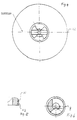
- the lamp cap is used for train lights, the details of which in are not shown in the drawing. Will the Train light attached to a ceiling, that's the upper part of the lamp cap 1 as strain relief 2 educated. It bears an eyelet-shaped end 3 that for connecting the lower end of a traction device serves on which the train light is suspended and with which it can be brought to different heights. This requires according to the height adjustability Train cable not shown to the lamp Power reserve, which is also not shown, which however requires a non-slip Connection of the supply cable to the lamp cap 1 to be provided.
- the strain relief has 2 a neck 4 which has a notch 5 has, according to the outer radius of the cable is curved inside.
- the notch 5 goes from one Bypass 6 into an axial introduction 7 over that ends in a hollow cylinder 8.
- a clamping tongue 9 (Fig. 6) presses the cable against the notch. All in all this increases the train resistance so much that the cable end emerging from the cylinder 8 is relieved of strain.
- the tongue 9 and the one described Notch form a structural unit with the strain relief, i.e. they are formed in one piece with this.
- the neck (4) of the strain relief (2) a half shell following the nipple (10) forms, which partially includes the lamp cable, and that the free end of the half-shell carries a fork, through their tines the lamp cable to the outside subsequent partial wrapping of the strain relief is led. It is recommended that on the half-shell a lamp cable support in diametrical Arrangement to the fork is arranged.
- the hollow cylinder 8 forms a nipple or spindle-shaped Approach 10, the outside with an external thread 11, 12 (Fig. 5) is provided.
- On the Thread can be screwed on a sleeve, which is not shown, but the strain relief 2 and the lower end of the power reserve of the spiral coiled supply cable.
- the nipple 10 of the strain relief 2 forms a structural unit with a roof cap 14.
- This forms a Laminating the underlying parts and covering them if necessary the opening of a lamp glass, which is also not shown.
- the roof cap carries a hollow cylinder 15, a claw 17, 18 over each of its lower edge 16 protrudes. These claws are diametrically on the Cylinder 15 arranged in one piece with this.
- she can with their inner projections 19, 20 in the outer grooves of a lamp holder, not shown snap into place with their cable entry supported on the inner edge 21 of the lamp cap 1.
- the lower edge (16) is used in the fully assembled Luminaire to support the upper edge of the Lamp holder.
- the strain relief 2 forms with the roof cap 14 Structural unit, i.e. the parts consist of one Piece, which in turn forms a shaped body.
- This molded body is made of plastic in one Injection mold made.
- Fig. 4 shows the possible Mold separation at 22.
- the molded body is general designated 23 (Fig. 4).
- the described claws 17, 18 are on the underside the roof cap, namely on the cylinder described 15 and on the inside 25 of the roof cap molded on immediately.
- the claw approach consists of a ring 26 which in Area of each claw shaft is reinforced and between the reinforcements as at 29 and 30 in Fig. 2, is made narrower. Inside, namely at 31, the ring has an inner cylindrical surface 31. This is flush with the inner surface of the Hollow cylinder 15, which is designated 32. she ends on the inside 33 of the roof cap 14. Die In contrast, the outside of the ring has a transition curvature 34 in the roof cap 14, which below the end of the inner surface 32 on the roof cap 14 is arranged.
- the outer edge of the roof cap 14 is reinforced at 34. This creates a secure support on the Lamp glass secured.
Landscapes
- Engineering & Computer Science (AREA)
- General Engineering & Computer Science (AREA)
- Arrangement Of Elements, Cooling, Sealing, Or The Like Of Lighting Devices (AREA)
- Non-Portable Lighting Devices Or Systems Thereof (AREA)
- Arrangements Of Lighting Devices For Vehicle Interiors, Mounting And Supporting Thereof, Circuits Therefore (AREA)
- Automobile Manufacture Line, Endless Track Vehicle, Trailer (AREA)
- Train Traffic Observation, Control, And Security (AREA)
Description
- Fig. 1
- die erfindungsgemäße Lampenkappe im Längsschnitt,
- Fig. 2
- in der Fig. 1 entsprechender Darstellung die Lampenkappe in einer gegenüber der Fig. 1 um 90° verdrehten Stellung,
- Fig. 3
- eine Draufsicht auf den Gegenstand der Fig. 2, der in einer Ansicht von unten wiedergegeben ist,
- Fig. 4
- eine Draufsicht auf den Gegenstand der Fig. 2, der die Lampenkappe von oben zeigt,
- Fig. 5
- eine Einzelheit, die in Richtung des Pfeils V der Fig. 2 angegeben ist und
- Fig. 6
- einen Horizontalschnitt durch den Anschluß für das Stromzuleitungskabel im Zugentlaster.
Claims (7)
- Lampenkappe (1) für Hängeleuchten, insbesondere Zugleuchten mit einem Zugentlaster (2), welcher zur Herstellung einer rutschfesten Verbindung (5-7) des Zuleitungskabels mit der Kappe (1) dient und außerdem vorzugsweise zur Befestigung einer Hülse eingerichtet ist, welche das kappenseitige Ende des spiralförmig gewickelten Zuleitungskabels sowie die rutschfeste Verbindung (5-7) abdeckt, mit einer Dachkappe, die mit dem Zugentlaster eine Baueinheit bildet, die mit einem Formkörper (23) verwirklicht ist, sowie mit einer Rastkappe, welche eine Lampenfassung mit mehreren Klauen (17, 18) hält, die an der Unterseite (25) der Dachkappe (14) unmittelbar angeformt sind, wobei auf eine gesonderte Kabeldurchführung verzichtet wird, dadurch gekennzeichnet, daß die Hülse auf ein Außengewinde (11, 12) eines Nippels (10) des Zugentlasters (2) aufschraubbar ist und der Nippel (10) mit seinem unteren Ende (14) an der Dachkappe (14) übergangslos ansetzt, wobei der Zugentlaster (2) eine rutschfeste Verbindung (9) für das untere Ende eines Zugmittels aufweist, die die Hülse abdeckt, wobei die rutschfeste Verbindung des Lampenkabels aus einem an eine Öse (3) ansetzenden Hals (4) und einer Kerbe (5) besteht, welche aus einer Umführung (6) mit einem gekrümmten Übergang (7) in einen Zylinder (8) übergeht, welcher den Nippel (10) durchsetzt und daß die Dachkappe eine Kaschierung bildet, wobei die Klauen (17, 18) an einem Ring ansetzen, der in einen Hohlzylinder (15) übergeht, den die Dachkappe in ihrem Inneren trägt und von dessen unterem Rand (17-20) eines Klauenpaares (17, 18) vorragt, dessen Klauen (19, 20) einander gegenüberstehen und wobei der Ring (26) eine innere Zylinderfläche (31) aufweist, welche mit der Innenfläche (35) des Hohlzylinders (15) fluchtet und an der inneren Krümmung (33) der Dachkappe endet, während die Außenseite des Ringes (26) eine Übergangskrümmung (34) in die Innenseite der Dachkappe (15) aufweist, welche unterhalb des Endes der Innenfläche (32) an der Dachkappe (14) angeordnet ist.
- Lampenkappe nach Anspruch 1, dadurch gekennzeichnet, daß der Rand (34) der Dachkappe (14) verstärkt ist.
- Lampenkappe nach einem der Ansprüche 1 bis 2, dadurch gekennzeichnet, daß ihre Baueinheit aus Spritzguß besteht und die Spritzgußform zweiteilig ausgebildet ist, wobei die Trennebene (22) eine Öse (3) in Längsrichtung durchsetzt, welche den Anschluß für das Zugmittel bildet.
- Lampenkappe nach einem der Ansprüche 1 bis 3, dadurch gekennzeichnet, daß die rutschfeste Verbindung des Lampenkabels aus einem an die Öse (3) ansetzenden Hals (4) des Zugentlasters (2) und einer Kerbe (5) besteht, welche aus einer Umführung (6) mit einem gekrümmten Übergang (7) in einen Zylinder (8) übergeht, welcher den Nippel (10) des Zugentlasters (2) durchsetzt.
- Lampenkappe nach einem der Ansprüche 1 bis 4, dadurch gekennzeichnet, daß der Hals (4) des Zugentlasters (2) im Anschluß an den Nippel (10) eine Halbschale bildet, die das Lampenkabel teilweise umfaßt, und daß das freie Ende der Halbschale eine Gabel trägt, durch deren Zinken das Lampenkabel nach außen mit anschließender teilweiser Umschlingung des Zugentlasters geführt ist.
- Lampenkappe nach Anspruch 5, dadurch gekennzeichnet, daß auf der Halbschale eine Lampenkabelstütze in diametraler Anordnung zu der Gabel angeordnet ist.
- Lampenkappe nach einem der Ansprüche 1 bis 6, dadurch gekennzeichnet, daß der untere Rand (16) des Hohlzylinders (15) zur Abstützung der Lampenfassung dient.
Applications Claiming Priority (4)
| Application Number | Priority Date | Filing Date | Title |
|---|---|---|---|
| DE4203063 | 1992-02-04 | ||
| DE19924203063 DE4203063A1 (de) | 1992-02-04 | 1992-02-04 | Lampenkappe fuer zugleuchten |
| DE9206220U DE9206220U1 (de) | 1992-02-04 | 1992-05-09 | Lampenkappe für Zugleuchten |
| DE9206220U | 1992-05-09 |
Publications (2)
| Publication Number | Publication Date |
|---|---|
| EP0554502A1 EP0554502A1 (de) | 1993-08-11 |
| EP0554502B1 true EP0554502B1 (de) | 1998-03-11 |
Family
ID=25911487
Family Applications (1)
| Application Number | Title | Priority Date | Filing Date |
|---|---|---|---|
| EP92110370A Expired - Lifetime EP0554502B1 (de) | 1992-02-04 | 1992-06-19 | Lampenkappe für Hängeleuchten, insbesondere Zugleuchten |
Country Status (4)
| Country | Link |
|---|---|
| EP (1) | EP0554502B1 (de) |
| AT (1) | ATE163999T1 (de) |
| DE (2) | DE9206220U1 (de) |
| ES (1) | ES2114544T3 (de) |
Family Cites Families (2)
| Publication number | Priority date | Publication date | Assignee | Title |
|---|---|---|---|---|
| EP0279033A3 (de) * | 1987-02-18 | 1990-04-04 | Firma Arno Hermanns | Leuchtenpendel |
| SE456768B (sv) * | 1987-04-06 | 1988-10-31 | Artilux Ab | Anordning vid en lamphaallare |
-
1992
- 1992-05-09 DE DE9206220U patent/DE9206220U1/de not_active Expired - Lifetime
- 1992-06-19 ES ES92110370T patent/ES2114544T3/es not_active Expired - Lifetime
- 1992-06-19 AT AT92110370T patent/ATE163999T1/de not_active IP Right Cessation
- 1992-06-19 EP EP92110370A patent/EP0554502B1/de not_active Expired - Lifetime
- 1992-06-19 DE DE59209226T patent/DE59209226D1/de not_active Expired - Fee Related
Also Published As
| Publication number | Publication date |
|---|---|
| EP0554502A1 (de) | 1993-08-11 |
| ES2114544T3 (es) | 1998-06-01 |
| ATE163999T1 (de) | 1998-03-15 |
| DE9206220U1 (de) | 1992-09-17 |
| DE59209226D1 (de) | 1998-04-16 |
Similar Documents
| Publication | Publication Date | Title |
|---|---|---|
| DE3237892C2 (de) | ||
| EP0692405A2 (de) | Einstellsystem für einen Reflektor eines Fahrzeug-Scheinwerfers | |
| DE202011050587U1 (de) | Elektrisches Anschlussteil | |
| EP0554502B1 (de) | Lampenkappe für Hängeleuchten, insbesondere Zugleuchten | |
| EP1503026A2 (de) | Punkthalter | |
| DE19826833B4 (de) | Einfach zusammenbaubare, ästhetisch ansprechende Fahrzeugleuchte | |
| DE3241677C1 (de) | Betaetigungsaufsatz fuer einen Druck-Zugschalter | |
| DE2618311C3 (de) | Leuchte, insbesondere Strahlerleuchte | |
| EP0453640A2 (de) | Adapter | |
| EP0570954B1 (de) | Strassenbake | |
| DE4203063A1 (de) | Lampenkappe fuer zugleuchten | |
| DE29815368U1 (de) | Niedervolt-Deckeneinbauleuchte | |
| EP0751341B1 (de) | Auslegerarm für eine Aussenleuchte | |
| DE4119597A1 (de) | Schalthebel fuer kraftfahrzeuge | |
| EP1591715A2 (de) | Schutzrohrleuchte mit mehrteiligen Deckeln | |
| EP0621446B1 (de) | Leuchtenmontierung | |
| DE19538059C1 (de) | Warnleuchte für Fahrzeuge | |
| DE29913138U1 (de) | Mastbogen für Straßenleuchten | |
| DE29607524U1 (de) | Elektrische Stablampe mit Warnstabfunktion | |
| DE29612434U1 (de) | Leuchte | |
| DE4330304A1 (de) | Halter zum Befestigen von elektrischen Vorrichtungen an einem Zweirad | |
| DE3112503A1 (de) | "mastleuchtenanordnung" | |
| DE9206779U1 (de) | Schalthebel für Kraftfahrzeuge | |
| DE9217781U1 (de) | Hängeleuchtenzugbügel | |
| DE9314450U1 (de) | Gewinde-Ring |
Legal Events
| Date | Code | Title | Description |
|---|---|---|---|
| PUAI | Public reference made under article 153(3) epc to a published international application that has entered the european phase |
Free format text: ORIGINAL CODE: 0009012 |
|
| AK | Designated contracting states |
Kind code of ref document: A1 Designated state(s): AT BE CH DE DK ES FR GB GR IT LI LU MC NL PT SE |
|
| RBV | Designated contracting states (corrected) |
Designated state(s): AT BE CH DE ES FR IT LI NL PT |
|
| 17P | Request for examination filed |
Effective date: 19940128 |
|
| 17Q | First examination report despatched |
Effective date: 19941205 |
|
| GRAG | Despatch of communication of intention to grant |
Free format text: ORIGINAL CODE: EPIDOS AGRA |
|
| GRAG | Despatch of communication of intention to grant |
Free format text: ORIGINAL CODE: EPIDOS AGRA |
|
| GRAH | Despatch of communication of intention to grant a patent |
Free format text: ORIGINAL CODE: EPIDOS IGRA |
|
| GRAH | Despatch of communication of intention to grant a patent |
Free format text: ORIGINAL CODE: EPIDOS IGRA |
|
| GRAA | (expected) grant |
Free format text: ORIGINAL CODE: 0009210 |
|
| AK | Designated contracting states |
Kind code of ref document: B1 Designated state(s): AT BE CH DE ES FR IT LI NL PT |
|
| REF | Corresponds to: |
Ref document number: 163999 Country of ref document: AT Date of ref document: 19980315 Kind code of ref document: T |
|
| REG | Reference to a national code |
Ref country code: CH Ref legal event code: EP |
|
| REG | Reference to a national code |
Ref country code: CH Ref legal event code: NV Representative=s name: TROESCH SCHEIDEGGER WERNER AG |
|
| REF | Corresponds to: |
Ref document number: 59209226 Country of ref document: DE Date of ref document: 19980416 |
|
| RAP2 | Party data changed (patent owner data changed or rights of a patent transferred) |
Owner name: BELITZ, RAINER |
|
| ITF | It: translation for a ep patent filed | ||
| REG | Reference to a national code |
Ref country code: ES Ref legal event code: FG2A Ref document number: 2114544 Country of ref document: ES Kind code of ref document: T3 |
|
| ET | Fr: translation filed | ||
| NLT2 | Nl: modifications (of names), taken from the european patent patent bulletin |
Owner name: BELITZ, RAINER |
|
| REG | Reference to a national code |
Ref country code: PT Ref legal event code: SC4A Free format text: AVAILABILITY OF NATIONAL TRANSLATION Effective date: 19980415 |
|
| PLBE | No opposition filed within time limit |
Free format text: ORIGINAL CODE: 0009261 |
|
| STAA | Information on the status of an ep patent application or granted ep patent |
Free format text: STATUS: NO OPPOSITION FILED WITHIN TIME LIMIT |
|
| 26N | No opposition filed | ||
| PGFP | Annual fee paid to national office [announced via postgrant information from national office to epo] |
Ref country code: PT Payment date: 19991230 Year of fee payment: 8 Ref country code: FR Payment date: 19991230 Year of fee payment: 8 Ref country code: CH Payment date: 19991230 Year of fee payment: 8 Ref country code: AT Payment date: 19991230 Year of fee payment: 8 |
|
| PGFP | Annual fee paid to national office [announced via postgrant information from national office to epo] |
Ref country code: NL Payment date: 19991231 Year of fee payment: 8 Ref country code: ES Payment date: 19991231 Year of fee payment: 8 |
|
| PGFP | Annual fee paid to national office [announced via postgrant information from national office to epo] |
Ref country code: BE Payment date: 20000119 Year of fee payment: 8 |
|
| PG25 | Lapsed in a contracting state [announced via postgrant information from national office to epo] |
Ref country code: AT Free format text: LAPSE BECAUSE OF NON-PAYMENT OF DUE FEES Effective date: 20000619 |
|
| PG25 | Lapsed in a contracting state [announced via postgrant information from national office to epo] |
Ref country code: ES Free format text: THE PATENT HAS BEEN ANNULLED BY A DECISION OF A NATIONAL AUTHORITY Effective date: 20000620 |
|
| PG25 | Lapsed in a contracting state [announced via postgrant information from national office to epo] |
Ref country code: LI Free format text: LAPSE BECAUSE OF NON-PAYMENT OF DUE FEES Effective date: 20000630 Ref country code: CH Free format text: LAPSE BECAUSE OF NON-PAYMENT OF DUE FEES Effective date: 20000630 Ref country code: BE Free format text: LAPSE BECAUSE OF NON-PAYMENT OF DUE FEES Effective date: 20000630 |
|
| BERE | Be: lapsed |
Owner name: BELITZ RAINER Effective date: 20000630 |
|
| PG25 | Lapsed in a contracting state [announced via postgrant information from national office to epo] |
Ref country code: PT Free format text: LAPSE BECAUSE OF NON-PAYMENT OF DUE FEES Effective date: 20001231 |
|
| PG25 | Lapsed in a contracting state [announced via postgrant information from national office to epo] |
Ref country code: NL Free format text: LAPSE BECAUSE OF NON-PAYMENT OF DUE FEES Effective date: 20010101 |
|
| REG | Reference to a national code |
Ref country code: CH Ref legal event code: PL |
|
| PG25 | Lapsed in a contracting state [announced via postgrant information from national office to epo] |
Ref country code: FR Free format text: LAPSE BECAUSE OF NON-PAYMENT OF DUE FEES Effective date: 20010228 |
|
| NLV4 | Nl: lapsed or anulled due to non-payment of the annual fee |
Effective date: 20010101 |
|
| PGFP | Annual fee paid to national office [announced via postgrant information from national office to epo] |
Ref country code: DE Payment date: 20010328 Year of fee payment: 9 |
|
| REG | Reference to a national code |
Ref country code: FR Ref legal event code: ST |
|
| REG | Reference to a national code |
Ref country code: PT Ref legal event code: MM4A Free format text: LAPSE DUE TO NON-PAYMENT OF FEES Effective date: 20001231 |
|
| PG25 | Lapsed in a contracting state [announced via postgrant information from national office to epo] |
Ref country code: DE Free format text: LAPSE BECAUSE OF NON-PAYMENT OF DUE FEES Effective date: 20020403 |
|
| REG | Reference to a national code |
Ref country code: ES Ref legal event code: FD2A Effective date: 20020304 |
|
| PG25 | Lapsed in a contracting state [announced via postgrant information from national office to epo] |
Ref country code: IT Free format text: LAPSE BECAUSE OF NON-PAYMENT OF DUE FEES Effective date: 20050619 |